Microfluidic Mixing: A Review

Abstract
:1. Introduction
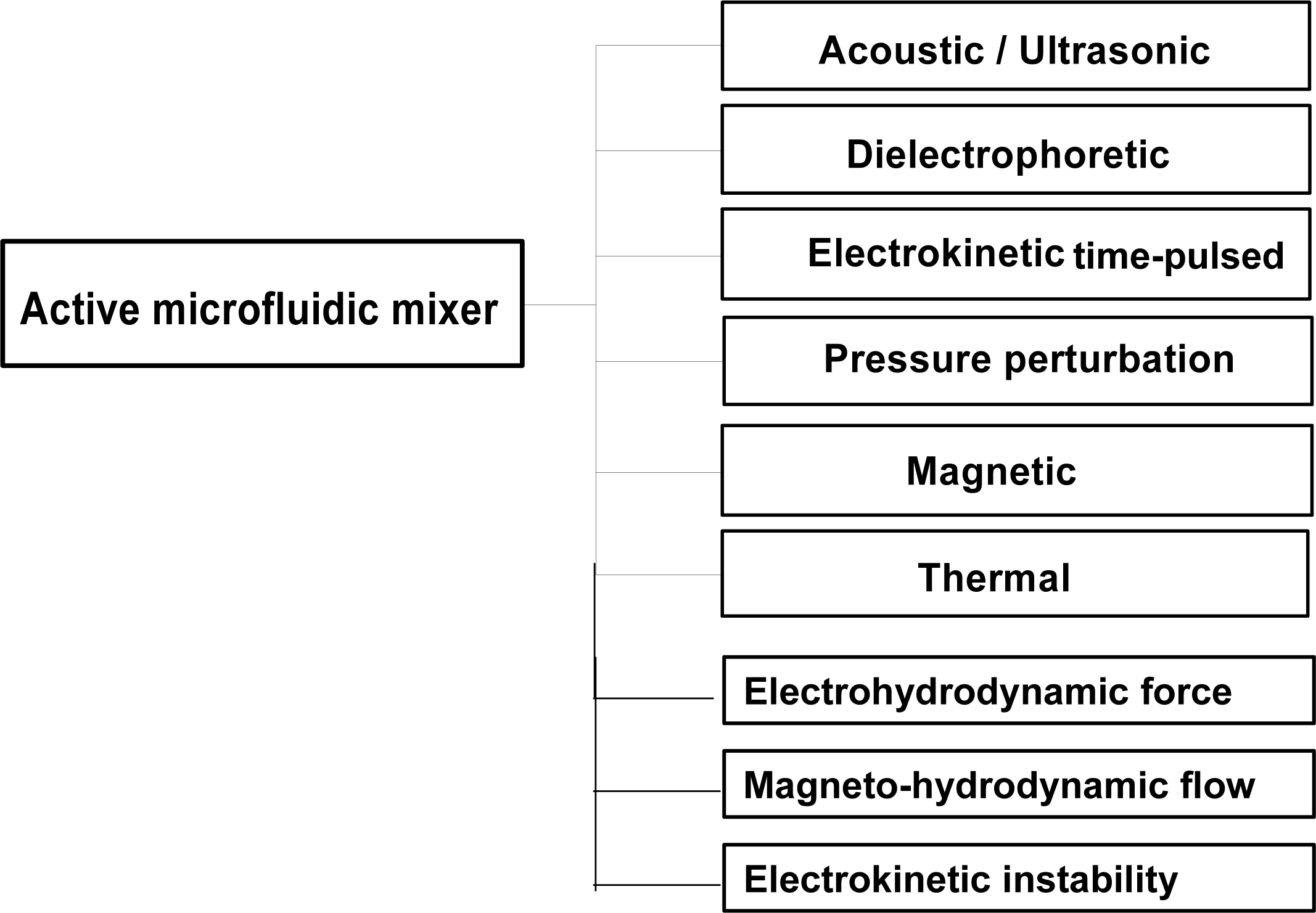
2. Active Microfluidic Mixers
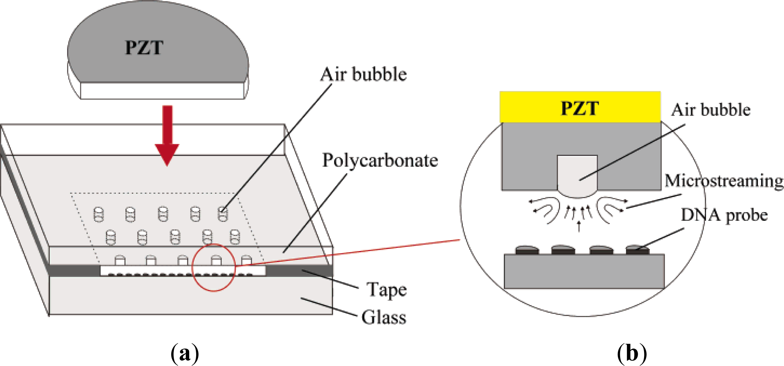
2.1. Acoustic/Ultrasonic Actuation [26–30]
2.2. Dielectrophoretic Force Actuation [31,32]
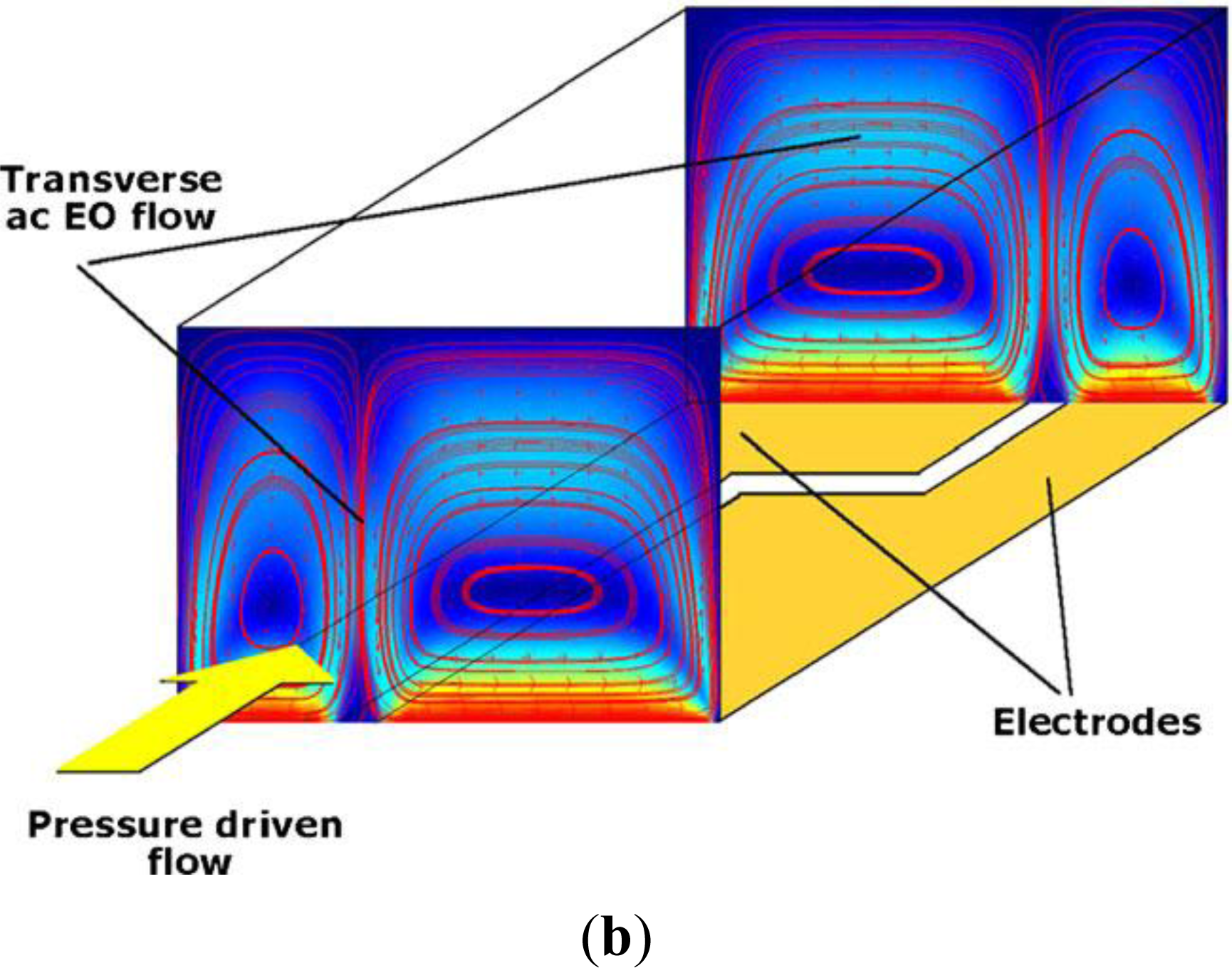
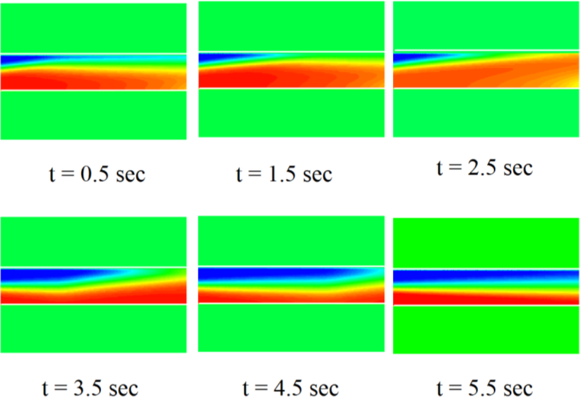
2.3. Electrokinetic Time-Pulsed Actuation [4,5,33–39]
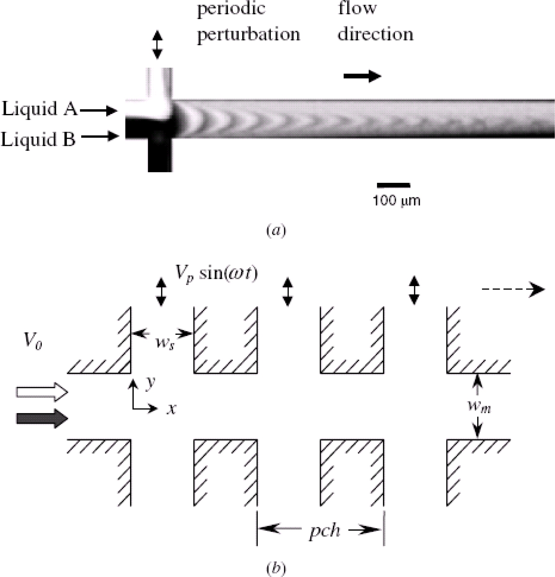
2.4. Pressure Perturbation [40]
2.5. Electrohydrodynamic (EHD) Force [6,7,41]
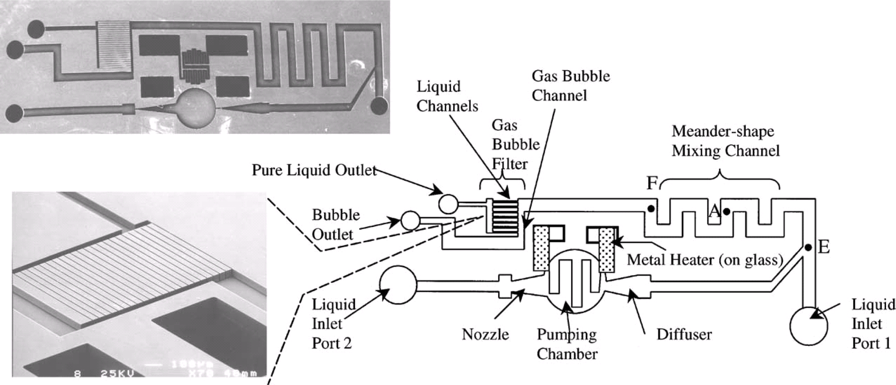
2.6. Thermal Actuation [8,42]
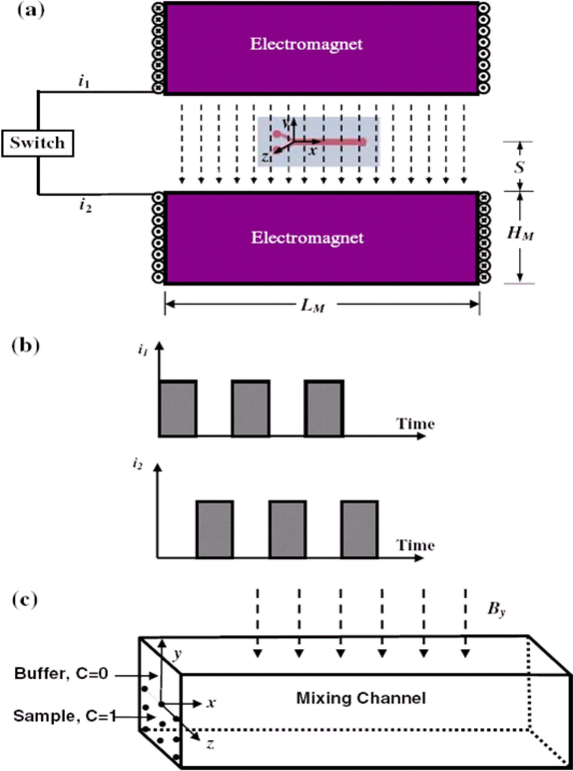
2.7. Magneto-Hydrodynamic Flow [43–45]
2.8. Electrokinetic Instability [10,11,46–48]
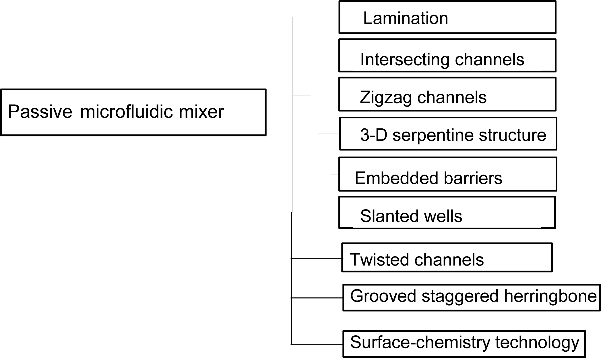
3. Passive Microfluidic Mixers
3.1. Lamination [13,14,58–60]
3.2. Intersecting Channels [61–63]
3.3. Zigzag Channels [64,65]
3.4. Three-Dimensional Serpentine Structures [16–18,66–70]
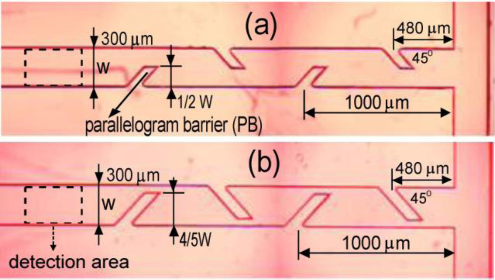
3.5. Embedded Barriers [21,71–73]
3.6. Slanted Wells [74–76]
3.7. Twisted Channels [23,77–79]
3.8. Surface-Chemistry Technology in Microchannels [80–83]
4. Conclusions
Acknowledgments
References
- Ahmed, D; Mao, X; Juluri, B; Huang, T. A fast microfluidic mixer based on acoustically driven sidewall-trapped microbubbles. Microfluid. Nanofluid 2009, 7, 727–731. [Google Scholar]
- Luong, T; Phan, V; Nguyen, N. High-throughput micromixers based on acoustic streaming induced by surface acoustic wave. Microfluid. Nanofluid 2011, 10, 619–625. [Google Scholar]
- Campisi, M; Accoto, D; Damiani, F; Dario, P. A soft-lithographed chaotic electrokinetic micromixer for efficient chemical reactions in lab-on-chips. J. Micro-Nano Mech 2009, 5, 69–76. [Google Scholar]
- Chen, CK; Cho, CC. Electrokinetically driven flow mixing utilizing chaotic electric fields. Microfluid. Nanofluid 2008, 5, 785–793. [Google Scholar]
- Lim, C; Lam, Y; Yang, C. Mixing enhancement in microfluidic channel with a constriction under periodic electro-osmotic flow. Biomicrofluidics 2010, 4, 014101. [Google Scholar]
- Du, Y; Zhang, Z; Yim, C; Lin, M; Cao, X. A simplified design of the staggered herringbone micromixer for practical applications. Biomicrofluidics 2010, 4, 024105. [Google Scholar]
- Zhang, Z; Yim, C; Lin, M; Cao, X. Quantitative characterization of micromixing simulation. Biomicrofluidics 2008, 2, 034104. [Google Scholar]
- Xu, B; Wong, T; Nguyen, N; Che, Z; Chai, J. Thermal mixing of two miscible fluids in a T-shaped microchannel. Biomicrofluidics 2010, 4, 044102. [Google Scholar]
- Wang, Y; Zhe, J; Chung, BTF; Dutta, P. A rapid magnetic particle driven micromixer. Microfluid. Nanofluid 2008, 4, 375–389. [Google Scholar]
- Lam, Y; Gan, H; Nguyen, N; Lie, H. Micromixer based on viscoelastic flow instability at low Reynolds number. Biomicrofluid 2009, 3, 014106. [Google Scholar]
- Huang, MZ; Yang, RJ; Tai, CH; Tsai, CH; Fu, LM. Application of electrokinetic instability flow for enhanced micromixing in cross-shaped microchannel. Biomed. Microdevices 2006, 8, 309–315. [Google Scholar]
- Meijer, HEH; Singh, MK; Kang, TG; den Toonder, JMJ; Anderson, PD. Passive and active mixing in microfluidic devices. Macromol. Symp 2009, 279, 201–209. [Google Scholar]
- Buchegger, W; Wagner, C; Lendl, B; Kraft, M; Vellekoop, M. A highly uniform lamination micromixer with wedge shaped inlet channels for time resolved infrared spectroscopy. Microfluid. Nanofluid 2011, 10, 889–897. [Google Scholar]
- Tofteberg, T; Skolimowski, M; Andreassen, E; Geschke, O. A novel passive micromixer: Lamination in a planar channel system. Microfluid. Nanofluid 2010, 8, 209–215. [Google Scholar]
- Lee, CY; Lin, CF; Hung, MF; Tsai, CH; Fu, LM. Experimental and numerical investigation into mixing efficiency of micromixers with different geometric barriers. Mater Sci Forum 2006, 505–507, 391–396. [Google Scholar]
- Chen, Z; Bown, MR; O’Sullivan, B; MacInnes, JM; Allen, RWK; Mulder, M; Blom, M; van’t Oever, R. Performance analysis of a folding flow micromixer. Microfluid. Nanofluid 2009, 7, 783–794. [Google Scholar]
- Kang, TG; Singh, MK; Anderson, PD; Meijer, HEH. A Chaotic Serpentine Mixer Efficient in th eCreeping Flow Regime: From Design Concept to Optimization. Microfluid. Nanofluid 2009, 6, 763–774. [Google Scholar]
- Moon, D; Migler, KB. Forced assembly and mixing of melts via planar polymer micro-mixing. Polymer 2010, 51, 3147–3155. [Google Scholar]
- Neerincx, PE; Denteneer, RPJ; Peelen, S; Meijer, HEH. Compact mixing using multiple splitting, stretching, and recombining flows. Macromol. Mater. Eng 2011, 296, 349–361. [Google Scholar]
- Lin, CH; Tsai, CH; Fu, LM. A rapid three-dimensional vortex micromixer utilizing self-rotation effects under low Reynolds number conditions. J. Micromech. Microeng 2005, 15, 935–943. [Google Scholar]
- Singh, MK; Anderson, PD; Meijer, HEH. Understanding and optimizing the SMX static mixer. Macromol. Rapid Commun 2009, 30, 362–376. [Google Scholar]
- Tsai, R; Wu, C. An efficient micromixer based on multidirectional vortices due to baffles and channel curvature. Biomicrofluidics 2011, 5, 014103. [Google Scholar]
- Hardt, S; Pennemann, H; Schonfeld, F. Theoretical and experimental characterization of a low-Reynolds number split-and-recombine mixer. Microfluid. Nanofluid 2006, 2, 237–248. [Google Scholar]
- Jain, M; Yeung, A; Nandakumar, K. Induced charge electro osmotic mixer: Obstacle shape optimization. Biomicrofluidics 2009, 3, 022413. [Google Scholar]
- Jain, M; Nandakumar, K. Novel index for micromixing characterization and comparative analysis. Biomicrofluidics 2010, 4, 031101. [Google Scholar]
- Liu, RH; Lenigk, R; Druyor, SRL; Yang, J; Grodzinski, P. Hybridization enhancement using cavitation microstreaming. Anal. Chem 2003, 75, 1911–1917. [Google Scholar]
- Yang, Z; Matsumoto, S; Goto, H; Matsumoto, M; Maeda, R. Ultrasonic micromixer for microfluidic systems. Sens. Actuators A 2001, 93, 266–272. [Google Scholar]
- Tsao, TR; Moroney, RM; Martin, BA; White, RM. Electrochemical detection of localized mixing produced by ultrasonic flexural waves. Proc. IEEE Ultrasonic Symp 1991, 1, 937–940. [Google Scholar]
- Rife, JC; Bell, MI; Horwitz, JS; Kabber, MN; Auyeung, RCY; Kim, WJ. Miniature valveless ultrasonic pumps and mixers. Sens. Actuators A 2000, 86, 135–140. [Google Scholar]
- Yaralioglu, GG; Wygant, IO; Marentis, TC; Khuri-Yakub, T. Ultrasonic mixing in microfluidic channels using integrated transducers. Anal. Chem 2004, 76, 3694–3698. [Google Scholar]
- Choi, E; Kim, B; Park, J. High-throughput microparticle separation using gradient traveling wave dielectrophoresis. J. Micromech. Microeng 2009, 19, 125014. [Google Scholar]
- Zhao, C; Yang, C. AC field induced-charge electroosmosis over leaky dielectric blocks embedded in a microchannel. Electrophoresis 2011, 32, 629–637. [Google Scholar]
- Lee, CY; Lee, GB; Fu, LM; Lee, KH; Yang, RJ. Electrokinetically driven active micro-mixers utilizing zeta potential variation induced by field effect. J. Micromech. Microeng 2004, 14, 1390–1398. [Google Scholar]
- Lin, CH; Fu, LM; Chien, YS. Microfluidic T-form mixer utilizing switching electroosmotic flow. Anal. Chem 2004, 76, 5265–5272. [Google Scholar]
- Fu, LM; Yang, RJ; Lin, CH; Chien, YS. A novel microfluidic mixer utilizing electrokinetic driving forces under low switching frequency. Electrophoresis 2005, 26, 1814–1824. [Google Scholar]
- Fu, LM; Lin, CH. A rapid DNA digestion system. Biomed. Microdevices 2007, 9, 277–286. [Google Scholar]
- Fu, LM; Tsai, CH. Design of interactively time-pulsed microfluidic mixers in microchips using numerical simulation. Jpn. J. Appl. Phys 2007, 46, 420–429. [Google Scholar]
- Leong, JC; Tsai, CH; Chang, CL; Lin, CF; Fu, LM. Rapid microfluidic mixers utilizing dispersion effect and interactively time-pulsed injection. Jpn. J. Appl. Phys 2007, 46, 5345–5352. [Google Scholar]
- Yan, D; Yang, C; Miao, J; Lam, Y; Huang, X. Enhancement of electrokinetically driven microfluidic T-mixer using frequency modulated electric field and channel geometry effects. Electrophoresis 2009, 30, 3144–3152. [Google Scholar]
- Niu, X; Lee, YK. Efficient spatial-temporal chaotic mixing in microchannels. J. Micromech. Microeng 2003, 13, 454–462. [Google Scholar]
- El Moctar, AO; Aubry, N; Batton, J. Electro-hydrodynamic micro-fluidic mixer. Lab Chip 2003, 3, 273–280. [Google Scholar]
- Tsai, JH; Lin, L. Active micofluidic mixer and gas bubble filter driven by thermal bubble micropump. Sens Actuators, A 2002, 97–98, 665–671. [Google Scholar]
- Bau, HH; Zhong, J; Yi, M. A minute magneto hydro dynamic (MHD) mixer. Sens. Actuators B 2001, 79, 207–215. [Google Scholar]
- Yi, M; Qian, S; Bau, HH. A minute magneto hydro dynamic (MHD) chaotic stirrer. J. Fluid Mech 2002, 468, 153–177. [Google Scholar]
- Wen, CY; Lee, TL; Tsai, CH; Fu, LM. Rapid magnetic microfluidic mixer utilizing AC electromagnetic field. Electrophoresis 2009, 30, 4179–4186. [Google Scholar]
- Chen, CH; Lin, H; Lele, SK; Santiago, JG. Convective and absolute electrokinetic instability with conductivity gradients. J. Fluid Mech 2005, 524, 263–303. [Google Scholar]
- Fu, L; Hong, T; Wen, C; Tsai, C; Lin, C. Electrokinetic instability effects in microchannels with and without nanofilm coatings. Electrophoresis 2008, 29, 4871–4879. [Google Scholar]
- Tai, CH; Yang, RJ; Huang, MZ; Liu, CW; Tsai, CH; Fu, LM. Micromixer utilizing electrokinetic instability induced shedding effect. Electrophoresis 2006, 27, 4982–4990. [Google Scholar]
- Yang, S; Cheng, F; Yeh, C; Lee, G. Size-controlled synthesis of gold nanoparticles using a micro-mixing system. Microfluid. Nanofluid 2010, 8, 303–311. [Google Scholar]
- Guo, W; Lau, K; Fung, Y. Microfluidic chip-capillary electrophoresis for two orders extension of adjustable upper working range for profiling of inorganic and organic anions in urine. Electrophoresis 2010, 31, 3044–3052. [Google Scholar]
- Oh, K; Smith, B; Devasia, S; Riley, J; Chung, J. Characterization of mixing performance for bio-mimetic silicone cilia. Microfluid. Nanofluid 2010, 9, 645–655. [Google Scholar]
- Sun, C; Sie, J. Active mixing in diverging microchannels. Microfluid. Nanofluid 2010, 8, 485–495. [Google Scholar]
- Mahalanabis, M; Do, J; Almuayad, H; Zhang, J; Klapperich, C. An integrated disposable device for DNA extraction and helicase dependent amplification. Biomed. Microdevices 2010, 12, 353–359. [Google Scholar]
- Weng, C; Lien, K; Yang, S; Lee, G. A suction-type, pneumatic microfluidic device for liquid transport and mixing. Microfluid. Nanofluid 2011, 10, 301–310. [Google Scholar]
- Wang, J; Wang, C; Lin, C; Lei, H; Lee, G. An integrated microfluidic system for counting of CD4+/CD8+ T lymphocytes. Microfluid. Nanofluid 2011, 10, 531–541. [Google Scholar]
- Elizarov, A; Meinhart, C; Miraghaie, R; van Dam, R; Huang, J; Daridon, A; Heath, J; Kolb, H. Flow optimization study of a batch microfluidics PET tracer synthesizing device. Biomed. Microdevices 2011, 13, 231–242. [Google Scholar]
- den Toonder, J; Bos, F; Broer, D; Fillippini, L; Gillies, M; de Geode, J; Mol, T; Reijme, M; Talen, W; Wildebeek, H; Khatavkar, V; Anderson, P. Artificial cilia for active micro-fluidic mixing. Lab Chip 2008, 4, 533–541. [Google Scholar]
- Branebjerg, J. From microfluidic components to micro-TAS. Proceedings of Micro Total Analysis System Workshop, Enschede, The Netherlands, 21–22 November 1994.
- Scampavia, LD; Blankenstein, G; Ruzicka, J; Christian, GD. A coaxial jet mixer for rapid kinetic analysis for chemical and biological microreactors. Anal. Chem 1995, 67, 2743–2749. [Google Scholar]
- Wong, SH; Ward, MCL; Wharton, CW. Micro T-mixer as rapid mixing micromixer. Sens. Actuators B 2004, 100, 359–379. [Google Scholar]
- Bertsch, A; Heimgartner, S; Cousseau, P; Renaud, P. Static micromixers based on large-scale industrial mixer geometry. Lab Chip 2001, 1, 56–60. [Google Scholar]
- He, B; Burke, BJ; Zhang, X; Zhang, R; Regnier, FE. A picoliter-volume mixer for microfluidic analytical systems. Anal. Chem 2001, 73, 1942–1947. [Google Scholar]
- Melin, J; Gimenez, G; Roxhed, N; van der Wijngaart, W; Stemme, G. A fast passive and planar liquid sample micromixer. Lab Chip 2004, 4, 214–219. [Google Scholar]
- Mengeaud, V; Josserand, J; Girault, HH. Mixing processes in a zigzag microchannel: Finite element simulations and optical study. Anal. Chem 2002, 174, 4279–4286. [Google Scholar]
- Hong, CC; Choi, JW; Ahn, CH. A novel in-plane passive microfluidic mixer with modified Tesla structures. Lab Chip 2003, 4, 109–113. [Google Scholar]
- Stroock, AD; Dertinger, SKW; Ajdari, A; Mezic, I; Stone, HA; Whitesides, GM. Chaotic mixer for microchannels. Science 2002, 295, 647–651. [Google Scholar]
- Vijayendran, RA; Motsegood, KM; Beebe, DJ; Leckband, DE. Evaluation of a three-dimensional micromixer in a surface-based biosensor. Langmuir 2003, 19, 1824–1828. [Google Scholar]
- Liu, YZ; Kim, BJ; Sung, HJ. Two-fluid mixing in a microchannel. Int. J. Heat Fluid Flow 2004, 25, 986–995. [Google Scholar]
- Liu, RH; Stremler, MA; Sharp, KV; Olsen, MG; Santiago, JG; Adrian, RJ; Aref, H; Beebe, DJ. Passive mixing in a three-dimensional serpentine microchannel. J. Microelectromech. Syst 2000, 9, 190–197. [Google Scholar]
- Lin, CH; Tsai, CH; Pan, CW; Fu, LM. Rapid circular microfluidic mixer utilizing unbalanced driving force. Biomed. Microdevices 2007, 9, 43–50. [Google Scholar]
- Keoschkerjan, R; Richter, M; Boskovic, D; Schnürer, F; Lobbecke, S. Novel multifunctional microreaction unit for chemical engineering. Chem. Eng. J 2004, 101, 469–475. [Google Scholar]
- Kim, DS; Lee, SW; Kwon, TH; Lee, SS. A barrier embedded chaotic micromixer. J. Micromech. Microeng 2004, 14, 798–805. [Google Scholar]
- Kim, DS; Lee, IH; Know, TH; Cho, DW. A barrier embedded Kenics micromixer. J. Micromech. Microeng 2004, 14, 1294–1301. [Google Scholar]
- Johnson, TJ; Ross, D; Locascio, LE. Rapid Microfluidic Mixing. Anal. Chem 2002, 74, 45–51. [Google Scholar]
- Johnson, TJ; Locascio, LE. Characterization and optimization of slanted well designs for microfluidic mixing under electroosmotic flow. Lab Chip 2002, 2, 135–140. [Google Scholar]
- Yang, JT; Huang, KJ; Lin, YC. Geometric effects on fluid mixing in passive grooved micromixers. Lab Chip 2005, 5, 1140–1147. [Google Scholar]
- Jen, CP; Wu, CY; Lin, YC; Wu, CY. Design and simulation of the micromixer with chaotic advection in microchannels. Lab Chip 2003, 3, 77–81. [Google Scholar]
- Park, SJ; Kim, JK; Park, J; Chung, S; Chung, C; Chang, JK. Rapid three-dimensional passive rotation micromixer using the breakup process. J. Micromech. Microeng 2004, 14, 6–14. [Google Scholar]
- Aubin, J; Fletcher, DF; Xuereb, C. Design of micromixers using CFD modelling. Chem. Eng. Sci 2005, 60, 2503–2516. [Google Scholar] [Green Version]
- Hunter, RJ. Zeta Potential in Colloid Science: Principles and Applications; Academic Press: London, UK, 1981. [Google Scholar]
- Zeng, S; Chen, CH; Mikkelsen, J; Santiago, JG. Fabrication and characterization of electrokinetic micro pumps. Proceedings of 7th International Conference on Thermal and Thermomechanical Phenomenon in Electronic Systems (ITherm), Las Vegas, NV, USA, 23–26 May 2000; 2, pp. 31–36.
- Chang, CC; Yang, RJ. Computational analysis of electrokinetically driven flow mixing in microchannels with patterned blocks. J. Micromech. Microeng 2004, 14, 550–558. [Google Scholar]
- Biddiss, E; Erickson, D; Li, D. Heterogeneous surface charge enhanced micromixing for electrokinetic flows. Anal. Chem 2004, 76, 3208–3213. [Google Scholar]
- Kawabata, T; Wada, H; Watanabe, M; Satomura, S. Electrokinetic analyte transport assay: For A-fetoprotein immunoassay integrates mixing, reaction and separation on-chip. Electrophoresis 2008, 29, 1399–1406. [Google Scholar]
- Chen, L; Wang, G; Lim, C; Seong, G; Choo, J; Kang, S; Song, J. Evaluation of passive mixing behaviors in a pillar obstruction poly(dimethylsiloxane) microfluidic mixer using fluorescence microscopy. Microfluid. Nanofluid 2009, 7, 267–273. [Google Scholar]
- Hong, TF; Ju, WJ; Wu, M; Tai, CH; Tsai, CH; Fu, LM. Rapid prototyping of PMMA microfluidic chips utilizing a CO2 laser. Microfluid. Nanofluid 2010, 9, 1125–1133. [Google Scholar]
- Lee, M; Choi, S; Park, J. Rapid multivortex mixing in an alternately formed contraction-expansion array microchannel. Biomed. Microdevices 2010, 12, 1019–1026. [Google Scholar]
- Mao, X; Juluri, B; Lapsley, M; Stratton, Z; Huang, T. Milliseconds microfluidic chaotic bubble mixer. Microfluid. Nanofluid 2010, 8, 139–144. [Google Scholar]
- Jännig, O; Nguyen, N. A polymeric high-throughput pressure-driven micromixer using a nanoporous membrane. Microfluid. Nanofluid 2011, 10, 513–519. [Google Scholar]
- Marasso, S; Giuri, E; Canavese, G; Castagna, R; Quaglio, M; Ferrante, I; Perrone, D; Cocuzza, M. A multilevel Lab on chip platform for DNA analysis. Biomed. Microdevices 2011, 13, 19–27. [Google Scholar]


| Categories | Mixing Technique | Mixing Time (ms) | Mixing Length (μm) | Mixing Index | Reference |
|---|---|---|---|---|---|
| Acoustic/Ultrasonic | Acoustically driven sidewall-trapped microbubbles | 120 | 650 | 0.025 | [1] |
| Acoustic streaming induced by surface acoustic wave | 600 | 10,000 | 0.9 | [2] | |
| Dielectrophoretic | Chaotic advection based on Linked Twisted Map | - | 1000 | 0.85 | [3] |
| Electrokinetic time-pulsed | Chaotic electric fields | 100 | Width * 5.0 | 0.95 | [4] |
| Periodic electro-osmotic flow | - | 200 | 0.88 | [5] | |
| Electrohydrodynamic force | Staggered herringbone structure | - | 825 | 0.2 | [6] |
| Staggered herringbone structure | - | 2300 | 0.5 | [7] | |
| Thermal actuation | Thermal | - | 6000 | - | [8] |
| Magneto-hydrodynamic flow | High operating frequency | 1100 | 500 | 0.977 | [9] |
| Electrokinetic instability | Low Reynolds number | - | 1200 | 0.98 | [10] |
| Low Reynolds number | - | 1200 | 0..98 | [11] |
| Categories | Mixing Technique | Mixing Time (ms) | Mixing Length (μm) | Mixing Index | Reference |
|---|---|---|---|---|---|
| Lamination | Wedged shaped inlets | 1 | 1 | 0.9 | [13] |
| 90° rotation | - | - | 0.95 | [14] | |
| Zigzag channels | Elliptic-shape barriers | - | 10,000 | 0.96 | [15] |
| 3-D serpentine structure | Folding structure | 489 | - | 0.01 | [16] |
| Creeping structure | - | - | 0.015 | [17] | |
| Stacked shim structure | - | - | - | [18] | |
| Multiple splitting, stretching and recombining flows | - | - | - | [19] | |
| Unbalanced driving force | - | 815ψ | 0.91 | [20] | |
| Embedded barriers | SMX | - | - | - | [21] |
| Multidirectional vortices | - | 4255 | 0.72 | [22] | |
| Twisted channels | Split-and-recombine | 730 | 96,000 | ∼1 | [23] |
| Surface-chemistry | Obstacle shape | - | 1000 | 0.98 | [24] |
| T-/Y- mixer | - | 1000 | 0.95 | [25] |
© 2011 by the authors; licensee MDPI, Basel, Switzerland. This article is an open-access article distributed under the terms and conditions of the Creative Commons Attribution license (http://creativecommons.org/licenses/by/3.0/).
Share and Cite
Lee, C.-Y.; Chang, C.-L.; Wang, Y.-N.; Fu, L.-M. Microfluidic Mixing: A Review. Int. J. Mol. Sci. 2011, 12, 3263-3287. https://doi.org/10.3390/ijms12053263
Lee C-Y, Chang C-L, Wang Y-N, Fu L-M. Microfluidic Mixing: A Review. International Journal of Molecular Sciences. 2011; 12(5):3263-3287. https://doi.org/10.3390/ijms12053263
Chicago/Turabian StyleLee, Chia-Yen, Chin-Lung Chang, Yao-Nan Wang, and Lung-Ming Fu. 2011. "Microfluidic Mixing: A Review" International Journal of Molecular Sciences 12, no. 5: 3263-3287. https://doi.org/10.3390/ijms12053263