Robust Non-Wetting PTFE Surfaces by Femtosecond Laser Machining


Abstract
:
1. Introduction
2. Results and Discussion
2.1. Femtosecond Laser Micromachining
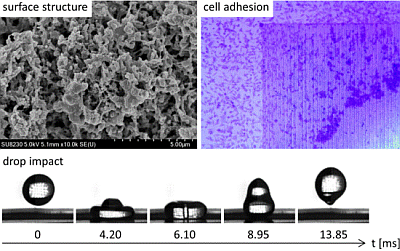
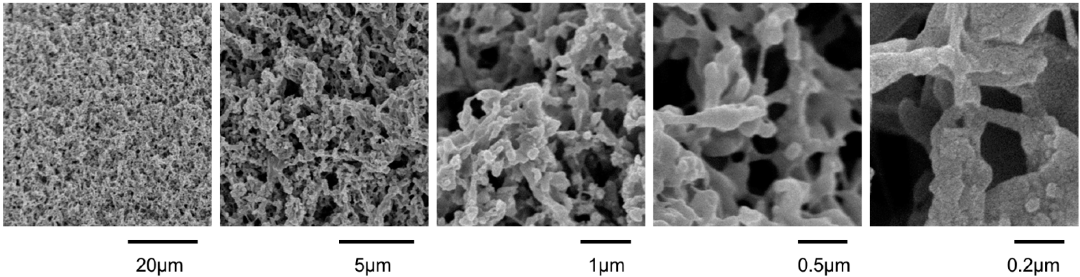
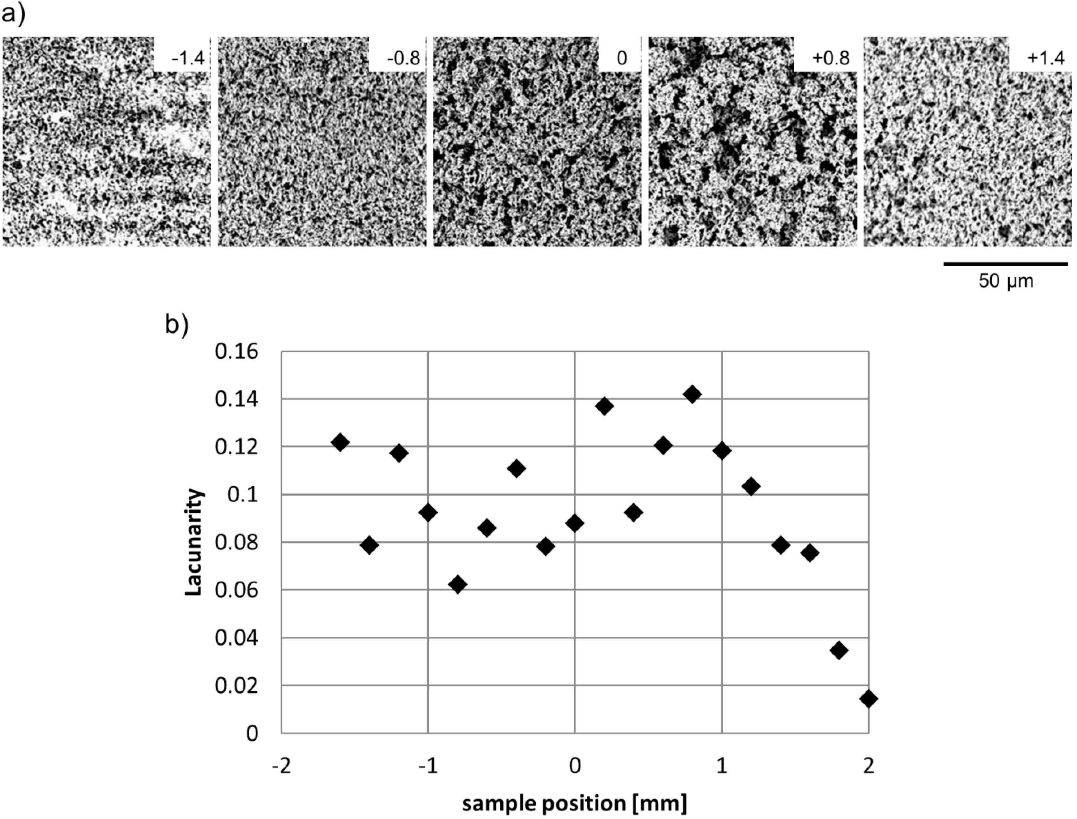
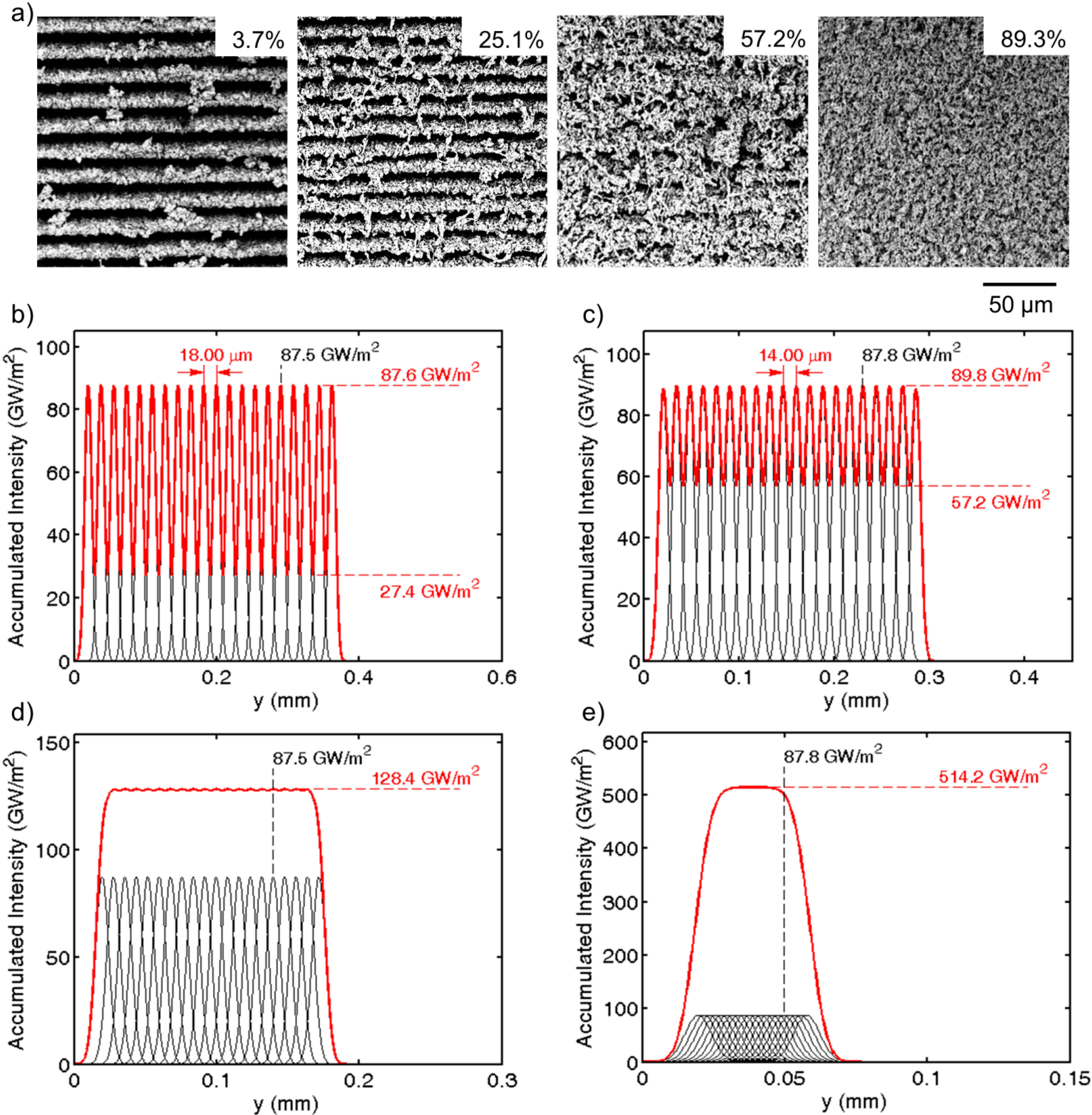
2.1.1. Homogeneous Surface Patterns


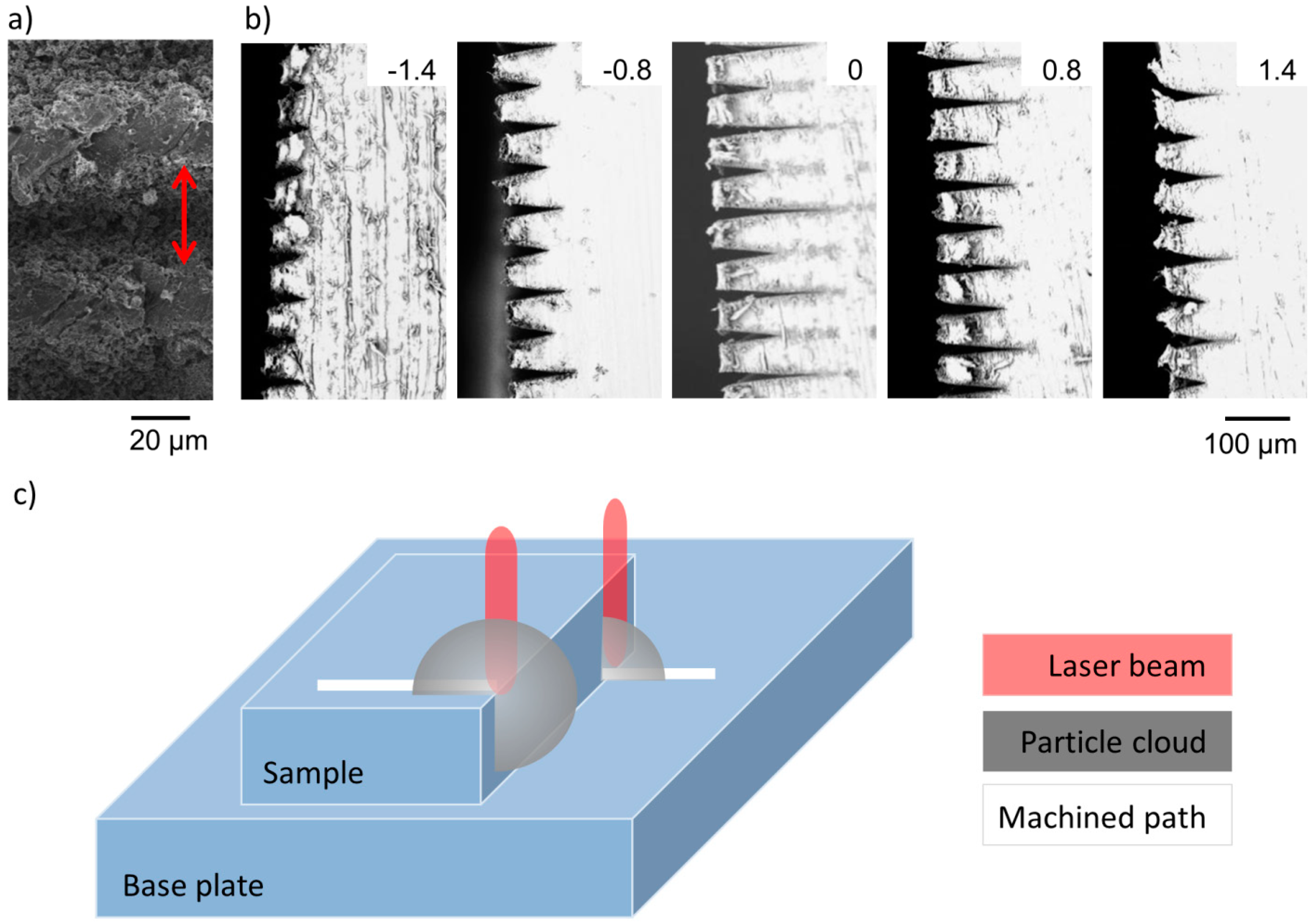
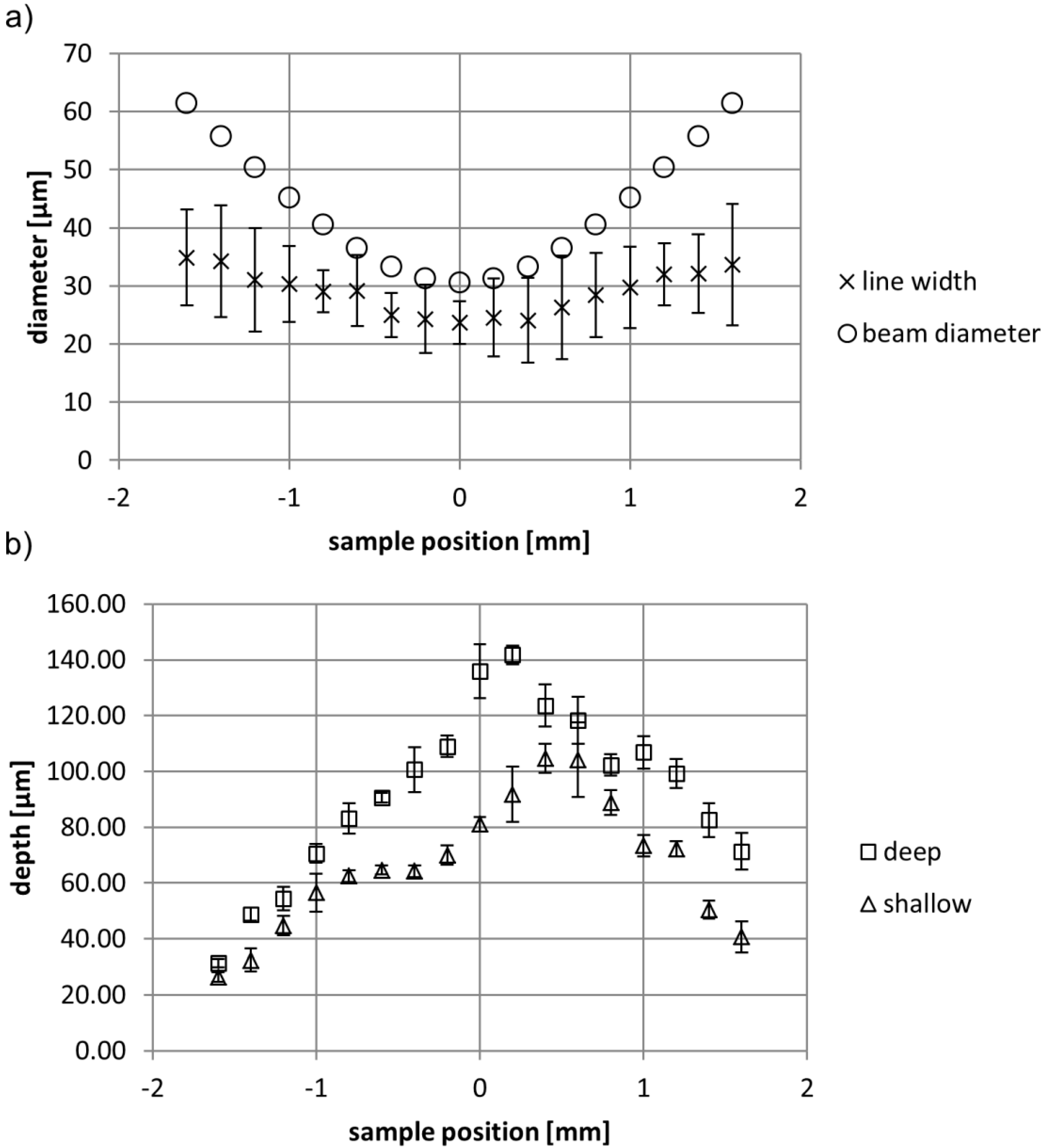
2.1.2. Line Experiments


2.1.3. Heterogeneous Surface Patterns

2.2. Wetting
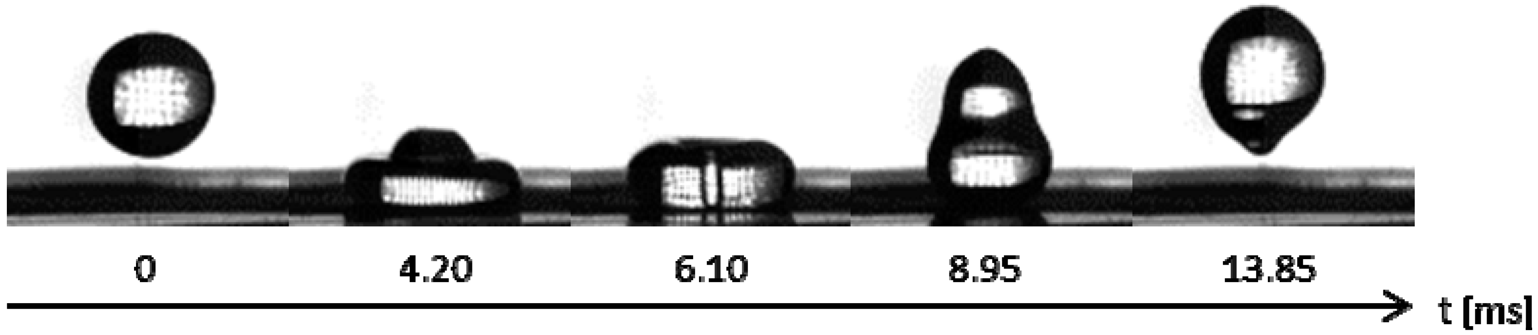
2.2.1. Drop Impact Experiments

2.2.2. Contact Angle Experiments

| Liquid | Surface Tension | Coating | Surface Structure | Sessile CA (°) |
|---|---|---|---|---|
| Water | 72 mN/m | x | flat | 107 ± 2 |
| fibrous | 151 ± 7 | |||
| gold | flat | 77 ± 4 | ||
| fibrous | 148 ± 6 | |||
| Glycerol | 63 mN/m | x | flat | 96 ± 8 |
| fibrous | 135 ± 6 | |||
| gold | flat | 74 ± 6 | ||
| fibrous | 123 ± 7 | |||
| Ethylene glycol | 47 mN/m | x | flat | 78 ± 4 |
| fibrous | 133 ± 7 | |||
| gold | flat | 60 ± 5 | ||
| fibrous | 97 ± 7 | |||
| Propylene glycol | 36 mN/m | x | flat | 71 ± 4 |
| fibrous | 124 ± 3 | |||
| gold | flat | 48 ± 4 | ||
| fibrous | 31 ± 4 |
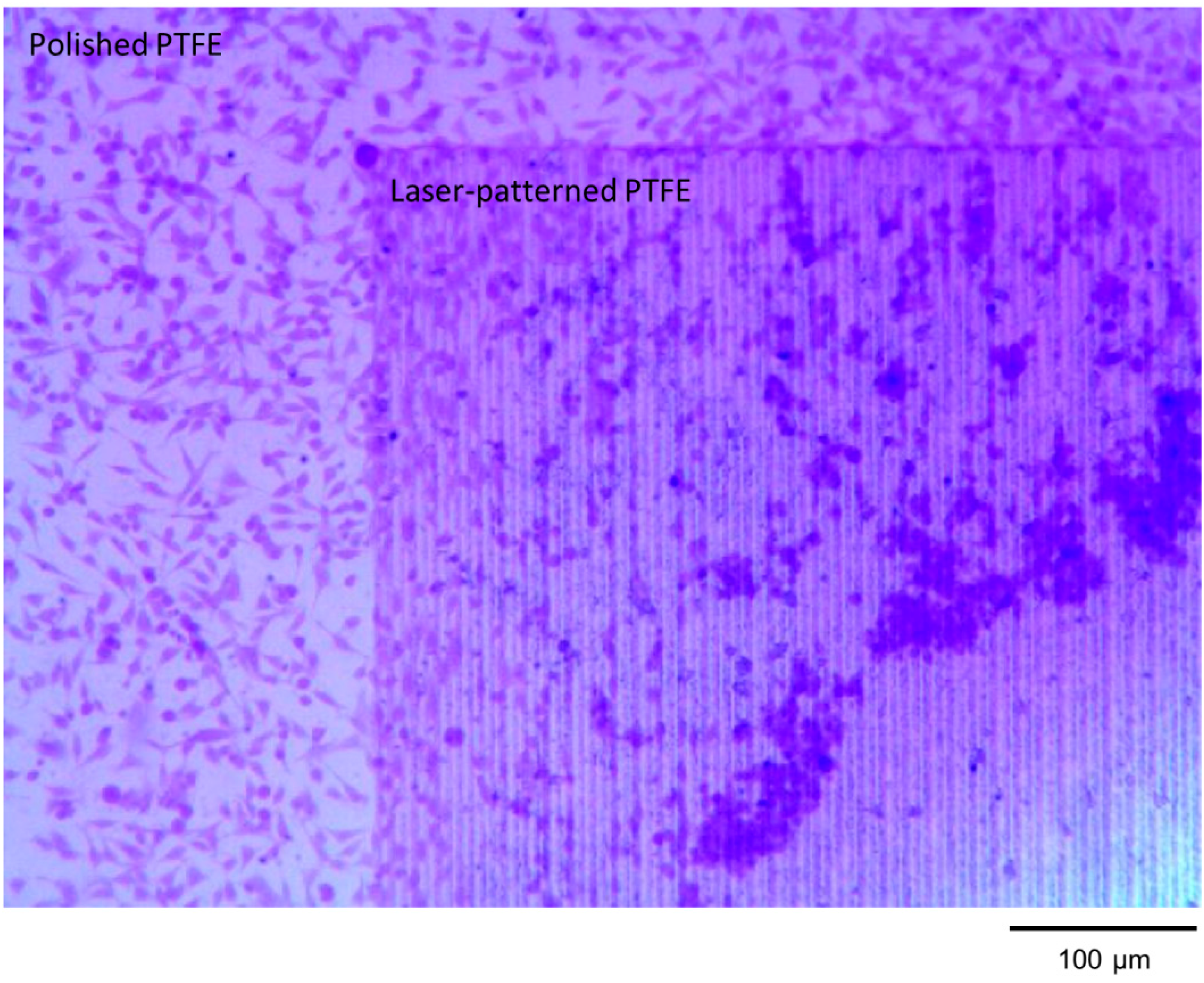
2.3. Bioadhesion

3. Experimental Section
4. Conclusions
Supplementary Files
Supplementary File 1Acknowledgments
Author Contributions
Conflicts of Interest
References
- Koch, K.; Barthlott, W. Superhydrophobic and superhydrophilic plant surfaces: An inspiration for biomimetic materials. Philos. Trans. R. Soc. Math. Phys. Eng. Sci. 2009, 367, 1487–1509. [Google Scholar] [CrossRef]
- Barthlott, W.; Neinhuis, C. Purity of the sacred lotus, or escape from contamination in biological surfaces. Planta 1997, 202, 1–8. [Google Scholar] [CrossRef]
- Wagner, T.; Neinhuis, C.; Barthlott, W. Wettability and contaminability of insect wings as a function of their surface sculptures. Acta Zool. 1996, 77, 213–225. [Google Scholar] [CrossRef]
- Hu, H.-M.; Watson, J.A.; Cribb, B.W.; Watson, G.S. Fouling of nanostructured insect cuticle: Adhesion of natural and artificial contaminants. Biofouling 2011, 27, 1125–1137. [Google Scholar]
- Byun, D.; Hong, J.; Saputra Ko, J.H.; Lee, Y.J.; Park, H.C.; Byun, B.K.; Lukes, J.R. Wetting characteristics of insect wing surfaces. J. Bionic Eng. 2009, 6, 63–70. [Google Scholar]
- Gao, X.; Jiang, L. Biophysics: Water-repellent legs of water striders. Nature 2004, 432, 36–36. [Google Scholar] [CrossRef]
- Goodwyn, P.J.P.; Voigt, D.; Fujisaki, K. Skating and diving: Changes in functional morphology of the setal and microtrichial cover during ontogenesis in aquarius paludum fabricius (heteroptera, gerridae). J. Morphol. 2008, 269, 734–744. [Google Scholar]
- Baum, C.; Simon, F.; Meyer, W.; Fleischer, L.-G.; Siebers, D.; Kacza, J.; Seeger, J. Surface properties of the skin of the pilot whale globicephala melas. Biofouling 2003, 19, 181–186. [Google Scholar] [CrossRef]
- Prowse, M.S.; Wilkinson, M.; Puthoff, J.B.; Mayer, G.; Autumn, K. Effects of humidity on the mechanical properties of gecko setae. Acta Biomater. 2011, 7, 733–738. [Google Scholar] [CrossRef]
- Barthlott, W.; Wiersch, S.; Čolić, Z.; Koch, K. Classification of trichome types within species of the water fern salvinia, and ontogeny of the egg-beater trichomes. Botany 2009, 87, 830–836. [Google Scholar] [CrossRef]
- Cassie, A.B.D.; Baxter, S. Wettability of porous surfaces. Trans. Faraday Soc. 1944, 40, 546–551. [Google Scholar] [CrossRef]
- Wenzel, R.N. Resistance of solid surfaces to wetting by water. Ind. Eng. Chem. 1936, 28, 988–994. [Google Scholar] [CrossRef]
- Guo, Z.; Liu, W.; Su, B.-L. Superhydrophobic surfaces: From natural to biomimetic to functional. J. Colloid Interface Sci. 2011, 353, 335–355. [Google Scholar] [CrossRef]
- Lu, C.; Xie, Y.; Yang, Y.; Cheng, M.M.C.; Koh, C.-G.; Bai, Y.; Lee, L.J.; Juang, Y.-J. New valve and bonding designs for microfluidic biochips containing proteins. Anal. Chem. 2006, 79, 994–1001. [Google Scholar]
- Gentile, F.; Coluccio, M.L.; Coppedè, N.; Mecarini, F.; Das, G.; Liberale, C.; Tirinato, L.; Leoncini, M.; Perozziello, G.; Candeloro, P.; et al. Superhydrophobic surfaces as smart platforms for the analysis of diluted biological solutions. ACS Appl. Mater. Interfaces 2012, 4, 3213–3224. [Google Scholar] [CrossRef]
- Gentile, F.; Coluccio, M.L.; Accardo, A.; Asande, M.; Cojoc, G.; Mecarini, F.; Das, G.; Liberale, C.; de Angelis, F.; Candeloro, P.; et al. Nanoporous- micropatterned- superhydrophobic surfaces as harvesting agents for few low molecular weight molecules. Microelectron. Eng. 2011, 88, 1749–1752. [Google Scholar] [CrossRef]
- Sousa, M.P.; Mano, J.F. Superhydrophobic paper in the development of disposable labware and lab-on-paper devices. ACS Appl. Mater. Interfaces 2013, 5, 3731–3737. [Google Scholar] [CrossRef] [Green Version]
- Chen, F.; Zhang, D.; Yang, Q.; Yong, J.; Du, G.; Si, J.; Yun, F.; Hou, X. Bioinspired wetting surface via laser microfabrication. ACS Appl. Mater. Interfaces 2013, 5, 6777–6792. [Google Scholar] [CrossRef]
- Shirk, M.D.; Molian, P.A. A review of ultrashort pulsed laser ablation of materials. J. Laser Appl. 1998, 10, 18–28. [Google Scholar] [CrossRef]
- Cheng, J.; Liu, C.-S.; Shang, S.; Liu, D.; Perrie, W.; Dearden, G.; Watkins, K. A review of ultrafast laser materials micromachining. Opt. Laser Technol. 2013, 46, 88–102. [Google Scholar] [CrossRef]
- Lippert, T.; Dickinson, J.T. Chemical and spectroscopic aspects of polymer ablation: Special features and novel directions. Chem. Rev. 2003, 103, 453–486. [Google Scholar] [CrossRef]
- Küper, S.; Stuke, M. Ablation of polytetrafluoroethylene (teflon) with femtosecond uv excimer laser pulses. Appl. Phys. Lett. 1989, 54, 4–6. [Google Scholar] [CrossRef]
- Kumagai, H.; Midorikawa, K.; Toyoda, K.; Nakamura, S.; Okamoto, T.; Obara, M. Ablation of polymer films by a femtosecond high-peak-power ti:Sapphire laser at 798 nm. Appl. Phys. Lett. 1994, 65, 1850–1852. [Google Scholar] [CrossRef]
- Adhi, K.P.; Owings, R.L.; Railkar, T.A.; Brown, W.D.; Malshe, A.P. Femtosecond ultraviolet (248 nm) excimer laser processing of teflon (ptfe). Appl. Surf. Sci. 2003, 218, 17–23. [Google Scholar]
- Hashida, M.; Mishima, H.; Tokita, S.; Sakabe, S. Non-thermal ablation of expanded polytetrafluoroethylene with an intense femtosecond-pulse laser. Opt. Express 2009, 17, 13116–13121. [Google Scholar] [CrossRef]
- Wang, Z.B.; Hong, M.H.; Lu, Y.F.; Wu, D.J.; Lan, B.; Chong, T.C. Femtosecond laser ablation of polytetrafluoroethylene (teflon) in ambient air. J. Appl. Phys. 2003, 93, 6375–6380. [Google Scholar] [CrossRef]
- Huang, M.Z.; Ming, Z. Femtosecond laser on the surface of PTFE. J. Funct. Mater. 2010, 41, 36. [Google Scholar]
- Cassady, A.I.; Hidzir, N.M.; Grøndahl, L. Enhancing expanded poly(tetrafluoroethylene) (ePTFE) for biomaterials applications. J. Appl. Polym. Sci. 2014, 131. [Google Scholar] [CrossRef]
- Wikol, M.; Hartmann, B.; Brendle, J.; Crane, M.; Beuscher, U.; Brake, J.; Shickel, T. Expanded polytetrafluoroethylene membranes and their applications. In Filtration and Purification in the Biopharmaceutical Industry, 2nd ed.; Jornitz, M.W., Meltzer, T.H., Eds.; Informa Healthcare USA, Inc.: New York, NY, USA, 2008; pp. 619–640. [Google Scholar]
- Lehr, J.; de Marchi, F.; Matus, L.; MacLeod, J.; Rosei, F.; Kietzig, A.-M. The influence of the gas environment on morphology and chemical composition of surfaces micro-machined with a femtosecond laser. Appl. Surf. Sci. 2014, unpublished work. [Google Scholar]
- Lehr, J.; Kietzig, A.-M. Production of homogenous micro-structures by femtosecond laser micro-machining. Opt. Lasers Eng. 2014, 57, 121–129. [Google Scholar] [CrossRef]
- Guo, Z.; Liu, W. Biomimic from the superhydrophobic plant leaves in nature: Binary structure and unitary structure. Plant Sci. 2007, 172, 1103–1112. [Google Scholar] [CrossRef]
- Ranella, A.; Barberoglou, M.; Bakogianni, S.; Fotakis, C.; Stratakis, E. Tuning cell adhesion by controlling the roughness and wettability of 3d micro/nano silicon structures. Acta Biomater. 2010, 6, 2711–2720. [Google Scholar] [CrossRef]
- Alves, N.M.; Shi, J.; Oramas, E.; Santos, J.L.; Tomás, H.; Mano, J.F. Bioinspired superhydrophobic poly(l-lactic acid) surfaces control bone marrow derived cells adhesion and proliferation. J. Biomed. Mater. Res. Part A 2009, 91A, 480–488. [Google Scholar] [CrossRef]
- Al-Kadi, O.S.; Watson, D. Texture analysis of aggressive and nonaggressive lung tumor ce ct images. IEEE Trans. Biomed. Eng. 2008, 55, 1822–1830. [Google Scholar] [CrossRef]
- Mandelbrot, B.B. The Fractal Geometry of Nature; W. H. Freeman and Company: New York, NY, USA, 1983; pp. 14–15. [Google Scholar]
© 2014 by the authors; licensee MDPI, Basel, Switzerland. This article is an open access article distributed under the terms and conditions of the Creative Commons Attribution license (http://creativecommons.org/licenses/by/3.0/).
Share and Cite
Liang, F.; Lehr, J.; Danielczak, L.; Leask, R.; Kietzig, A.-M. Robust Non-Wetting PTFE Surfaces by Femtosecond Laser Machining. Int. J. Mol. Sci. 2014, 15, 13681-13696. https://doi.org/10.3390/ijms150813681
Liang F, Lehr J, Danielczak L, Leask R, Kietzig A-M. Robust Non-Wetting PTFE Surfaces by Femtosecond Laser Machining. International Journal of Molecular Sciences. 2014; 15(8):13681-13696. https://doi.org/10.3390/ijms150813681
Chicago/Turabian StyleLiang, Fang, Jorge Lehr, Lisa Danielczak, Richard Leask, and Anne-Marie Kietzig. 2014. "Robust Non-Wetting PTFE Surfaces by Femtosecond Laser Machining" International Journal of Molecular Sciences 15, no. 8: 13681-13696. https://doi.org/10.3390/ijms150813681