Application of Sensing Techniques to Cellular Force Measurement


Abstract
: Cell traction forces (CTFs) are the forces produced by cells and exerted on extracellular matrix or an underlying substrate. CTFs function to maintain cell shape, enable cell migration, and generate and detect mechanical signals. As such, they play a vital role in many fundamental biological processes, including angiogenesis, inflammation, and wound healing. Therefore, a close examination of CTFs can enable better understanding of the cellular and molecular mechanisms of such processes. To this end, various force-sensing techniques for CTF measurement have been developed over the years. This article will provide a concise review of these sensing techniques and comment on the needs for improved force-sensing technologies for cell mechanics and biology research.1. Introduction
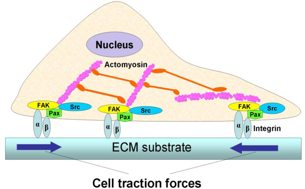
Cellular forces play a vital role in many fundamental biological processes. A variety of life activities, including heartbeats and body motions, rely on muscle contraction, which is ultimately determined by the intrinsic contraction of individual muscle cells. In muscle cells, cell contraction is generated by the continuous, high-speed sliding of the heads of myosin, a cellular motor protein, over actin filaments [1,2]. In non-muscle cells, a similar mechanism is used to generate intracellular tension [3]. When this intracellular tension is transmitted to the extracellular matrix (ECM) via focal adhesions (FAs), which form physical links between actin cytoskeleton and ECM, it is referred to as cell traction force (CTF) (Figure 1) [4–6].
CTFs are important in many aspects of cellular activities. Cells apply CTFs on their underlying substrates in order to enable cell migration [8,9]. Cells also use CTFs to sense the mechanical properties of their underlying substrate and adjust their adhesion and morphology. Moreover, CTFs are used to control cell shape and maintain cellular tensional homeostasis [10–12]. Therefore, CTFs are required for many fundamental biological processes, including morphogenesis, metastasis, angiogenesis, and wound healing.
In addition, CTFs are also necessary for mechano-signal transmission and transduction. Since CTFs are transmitted to ECM through FAs, which consist of diverse proteins including signaling proteins (e.g., integrins) and enzymes (e.g., kinases and phosphatases) [13], any biological, biochemical, or biomechanical stimuli acting on cells through ECM will likely cause changes in the assembly of FA proteins, the actin cytoskeleton, and actomyosin interactions These changes will in turn affect the “output” of CTFs. On the other hand, CTFs can deform the ECM network and hence produce stresses and strains in the matrix network, which in turn can modulate cellular functions such as DNA synthesis, ECM protein secretion, and even cell differentiation [6,14]. As such, CTF may be used as a useful “biophysical marker” to characterize phenotypic changes of individual cells.
In summary, a close examination of CTFs can enable better understanding of the cellular and molecular mechanisms of many important biological processes. To this end, a number of CTF-sensing techniques have been developed over the years. In this article, we will provide an overview of these cell force-sensing techniques and also illustrate their usage by giving examples of their applications.
2. CTF-Sensing Techniques
To date, a variety of techniques have been developed for measuring CTFs qualitatively or quantitatively. Such measurement methods can be divided into two categories: techniques for sensing the forces of a cell population and those for single cells. To measure the CTFs of a cell population, collagen-based gels with embedded cells are typically used. The gel shrinks as a result of the collective effect of cellular traction from the cell population, and the extent of such shrinkage represents the CTFs from the cell population. On the other hand, CTFs of individual cells can be detected using microscopy-based techniques, which mainly involve the use of deformable thin membranes, microfabricated structures, and hydrogels.
2.1. Cell population-based techniques
Cell population-based techniques are developed largely based on a cell-populated collagen gel (CPCG) model or its derivatives. CPCG was originally developed as an engineered skin graft substitute for burn patients and was, in fact, specially termed fibroblast-populated collagen lattice (FPCL) [15]. CPCG has been widely used as an in vitro model for measuring cell contractility [16]. In CPCG approaches, gels are used as a “force-sensing device”, with which contractile forces of cells are indirectly measured by changes in gel volume or area or directly measured with force-gauges [17–20]. As cellular contraction is directly related to CTFs, such methods are an indirect means to measure CTFs [21].
2.1.1. Gel geometric change-based CPCG models
Techniques that monitor the geometric changes of collagen gel during culture represent a classical and simple approach to measuring cellular contraction semi-quantitatively. According to the anchorage status of CPCG to the substrate during measurement, three types of CPCG models have been developed. In free-floating CPCG (FF-CPCG), the gel floats in cell culture medium without any constraints, and as a result, isotonic contraction is created, resulting in a decrease in gel diameter. In tethered CPCG (T-CPCG), the gel is tightly attached to a substrate and so cannot move or relax. This results in isometric contraction of the gel, leading to a decrease in the height of the tethered gel but not in its diameter. In tethered-delayed-released CPCG (TDR-CPCG), the cell-imbedded gel is first attached to a substrate for a certain period of time to allow tension development within the gel. The gel is then released and starts to contract isotonically as a result of unconstrained cellular contraction [21,22].
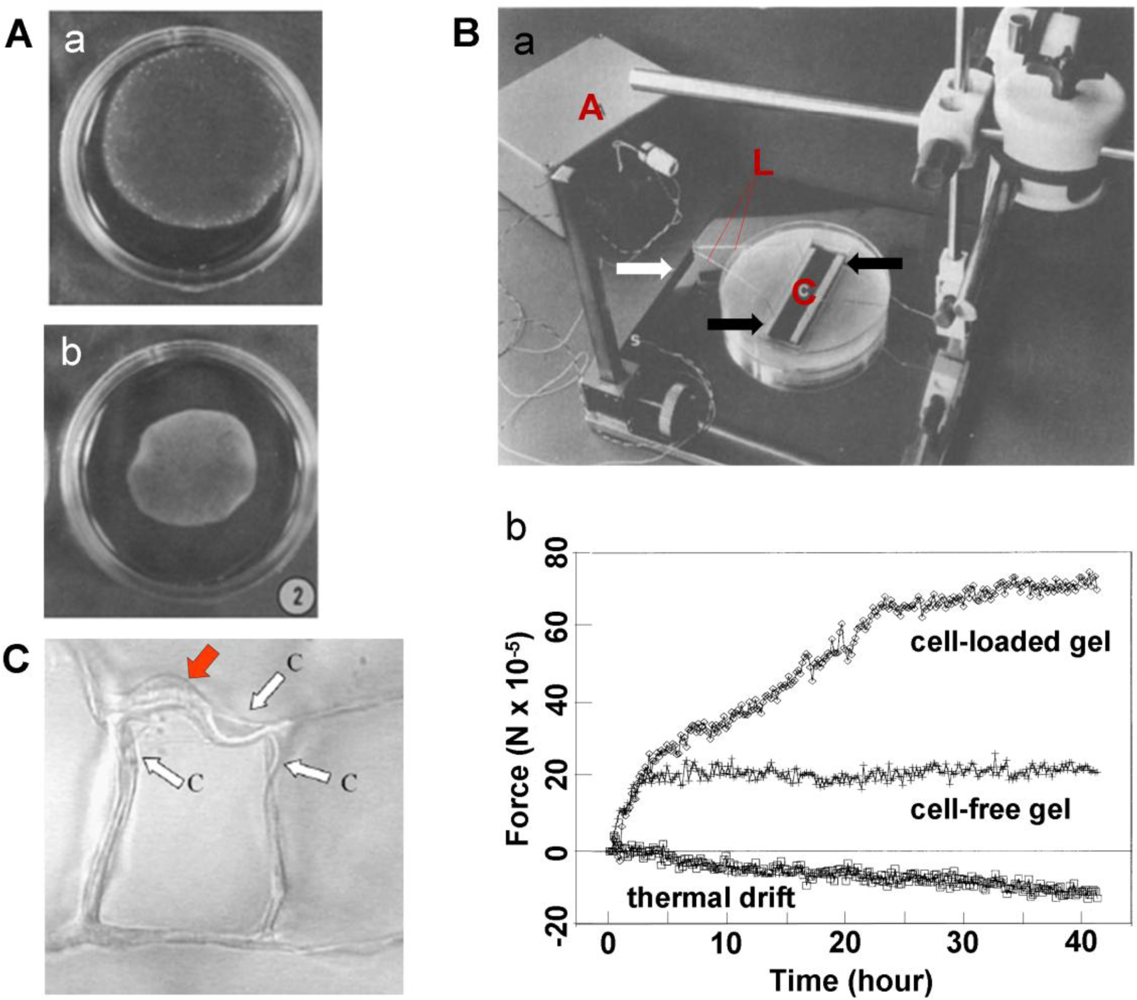
The CPCG-based approaches measure cellular forces by quantifying collagen gel shrinkage [23,24]. During culture, the size of the CPCG is progressively reduced to balance the cells-generated contraction (Figure 2A). Therefore, measuring the reduction in the geometric features (such as diameter of sphere-shaped gels, area or length of rectangular gels of FF-CPCG and TDR-CPCG, and height of T-CPCG) provides indirect quantification of cellular contractility [17,22,25].
A drawback of the geometry-dependent measurement methods is that they provide only a gross estimate of cellular contractility due to large variation and instability of gel geometry during culture. An improved method involves using a collagen-GAG foam-like gel to measure the contractile force of embedded cells [26]. In addition to calculating the averaged contractile force of a cell population from gross gel deformation, the open-cell structure of this gel also allows for determination of contraction by individual cells using conventional column buckling relationships. When cells are grown in the scaffold they deform their surrounding struts. By determining the deformation of struts, cell-mediated contractile force can be calculated according to Euler’s buckling relation and the hydrostatic compression end restraint. This approach extends previous methods for analyzing cell buckling of two-dimensional (2-D) substrates to three-dimensional (3-D) constructs and can therefore be used to estimate the contractile forces of individual cells in 3-D conditions. Such a technique is significant as it can be used for cell mechanics studies using porous tissue engineering scaffolds that are structurally similar to low-density, open-cell foams.
2.1.2. Culture force monitor
While conceptually simple, geometric change-based CPCG models lack sufficient sensitivity when the cellular contractile forces are relatively small. Directly sensing the force in CPCG with reasonably high sensitivity, therefore, represents a more favorable approach. This is achieved by attaching strain gauges to the CPCG to continuously track the changes in the strain or stress of the gel. Because of the ability to directly sense cellular forces, such a technique is specially termed culture force monitor (CFM). Depending on the sensitivity of the strain gauges, which function as force sensors, the CFM technique can measure small cellular contractile forces when geometric changes in gel are hardly detectable.
In a CFM system, the collagen gel can either float in medium or be tethered to an underlying substrate. In the setup developed by Delvoye et al., a floating collagen gel was restrained at both ends by curing the collagen on immobilized glass rods, one of which was connected to a strain gauge [17]. In tethered collagen gels, CFM measures the isometric contraction generated within the gel with minimal changes in its dimensions [27,28]. In a typical CFM system, two bars attached to a collagen gel are connected to a central measuring beam, to which strain gauges are attached in a full bridge network to give maximum sensitivity [19] (Figure 2B). Compared to the geometric change-based CPCG methods, the sensitivity of CFM is markedly higher. For example, a displacement as small as 0.5 mm, barely measurable using geometric change-based method [19], could be detected. As a matter of fact, CFM was able to sense cell-mediated force generation during the initial stages of contraction, which is otherwise too small to be detected [19]. In addition, different cell populations could be distinguished by comparing the contraction profiles of the cells. For example, using CFM measurement, ocular fibroblasts were shown to exhibit a marked difference in their contraction profiles—corneal fibroblasts generated the strongest contraction while scleral fibroblasts produced the weakest [29]. Therefore, such a technique may serve as a useful biophysical cell profiling tool to identify cells [30].
In light of the sensitivity of CFM technique, efforts have been made to improve its efficiency over the past two decades. For example, multi-station CFM systems consisting of four vertical cantilever beams with semiconductor strain gages have been developed [31–33]. Such CFM systems are able to test multiple samples simultaneously and facilitate statistical design and analysis of experiments. In addition, a dynamic CFM (D-CFM) system has also been developed. By using computer-controlled linear actuators, this system is able to apply precise motion waveforms to multiple CPCGs independently and detect the differences in force patterns [33]. Thus, such a system may facilitate the study of the effect of dynamic mechanical loads on cells, ECM remodeling, and cell-matrix interactions. A combination of CFM and time lapse reflection microscopy, a simultaneous imaging and micro-culture force monitor (SIM-CFM) system, has been developed to measure the mechanical strain generated during matrix contraction while simultaneously recording cell and matrix behaviors [34].
2.2. Single cell-based techniques
Cell population-based techniques are able to provide an estimation of the “averaged” forces of a group of cells. They also have the advantage that the measured forces of cells embedded in a 3-D matrix are more physiologically relevant to cells in vivo that reside in a 3-D tissue environment. However, these methods do not measure CTFs per se [35]. Meanwhile, cells are heterogeneous and the forces that they generate vary in a wide range. Therefore, sensing forces generated by individual cells is of special importance, especially in terms of relating cell behaviors to the mechanical characteristics of cells.
To this end, a few single cell-based techniques for sensing or measuring CTFs have been developed using optical or microelectronic approaches. All these techniques can determine CTFs of individual cells at sub-cellular level, meaning that they can “map” the CTFs of a single cell. A common feature of these techniques is that they all involve the use of deformable substrates that are compliant enough to sense the tiny forces generated by a single cell. Such substrates are either continuum sheets, including wrinkle-able thin silicone membranes [4,36,37] and fluorescent beads-embedded polyacrylamide gels [38–40], or non-continuous substrates, including microfabricated cantilever arrays [41] and micropost arrays [42–46].
2.2.1. Ultra-thin silicone membranes
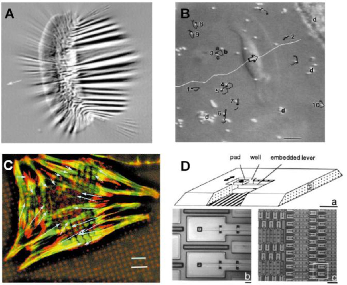
Early studies of cell mechanics used thin silicone membranes to demonstrate that fibroblasts created wrinkles on the membrane through CTFs (Figure 3A) [6,36,37]. While such a thin silicone membrane is able to “sense” small CTFs, this approach is only qualitative. This technique was further improved by estimating CTFs through applying a flexible micro-needle of known stiffness to reverse the wrinkles generated by the cell [47]. However, due to the fact that wrinkling is a nonlinear problem, there is currently no known mathematical method to accurately predict the wrinkles caused by a complex, non-isotropic CTF field. As a result, this approach cannot determine the absolute values of CTF.
Alternatively, techniques using micro-beads-embedded elastic membranes were developed in an attempt to track the displacements of micro-beads, which were used as position markers, and thereby determine CTFs at certain locations [48,49] (Figure 3B). Further, the use of micropatterned elastomer represents an important innovation, in which the surface of an elastic ultra-thin membrane is decorated with an array of fluorescent micro-dots of a fraction of a micron in height [4] (Figure 3C). By using the micro-dots as markers to determine substrate deformations, the CTFs at each FA of the cell can be determined using elasticity theory [7].
While the use of the micropatterned substrate simplifies the determination of CTFs-induced displacement fields, the stiffness of silicone membranes cannot be adjusted low enough to sense small deformations [50]. Therefore, these methods generally lack sufficient resolution in measuring small CTFs. Nevertheless, an advantage of such membrane-based techniques is that they can be easily integrated into micro-chips for biosensor applications [51].
2.2.2. Microfabricated cantilever array
A technique based on a micro-machined array of cantilever beams has been developed, partially for avoiding the complicated computation associated with wrinkling membranes and for determining the absolute values of forces generated by a cell (Figure 3D) [41]. In this method, cells were cultured on pads underlined with cantilever beams of known stiffness. When the cell applies CTFs and bends a cantilever beam, a force-sensing unit, the extent of bending is recorded and the CTF is then determined accordingly. Such a technique can reliably determine the CTFs of an individual cell. However, it can only determine the CTFs in one direction. Moreover, the fabrication of the device is complicated and costly. The resolution of this technique is not satisfactory either, due to the intrinsic limitation of the fabrication process.
2.2.3. Micropost force sensor array
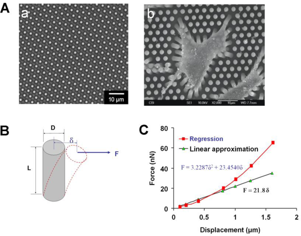
To overcome the limitations associated with cantilever arrays, CTF measurement techniques based on micropost force sensor arrays (MFSAs) have been developed in recent years [42–44,52,53]. In a MFSA, each micropost functions as an individual force-sensing unit and independently senses the CTFs locally applied by a cell. Specifically, when a cell adheres to the microposts, it exerts tensile forces at the top of microposts and causes lateral deflection in them (Figure 4A) [42]. Once the deflections of the microposts are obtained by imaging analysis, the CTFs can be determined based on the beam deflection-force relationship that has been calibrated, or be calculated according to well-established beam theory [54] (Figure 4B). However, such a linear relationship between deflection and force in the beam theory is no longer valid if the deflection exceeds a certain level, when regression approximation must be applied (Figure 4C).
Compared to micro-cantilevers which can only determine CTFs in a single direction [41], microposts in an array can detect CTFs in all directions. Therefore, MFSA technology is especially useful in mapping the forces during cell migration [44,55]. Another advantage of MFSA is that the microposts can also be used to apply localized mechanical forces to a cell under a magnetic field if magnetic nano-wires are embedded inside the microposts [56]. Similarly, taking advantage of the periodicity of the micropost array, an optical Moire-based traction forces mapping technique was explored by acquiring the diffracted Moire fringe pattern of the array instead of tracking the displacements of individual microposts [53]. This method may potentially determine CTFs at a higher resolution because of the magnification effect of Moire fringe pattern as well as lack of need to track or visualize individual microposts.
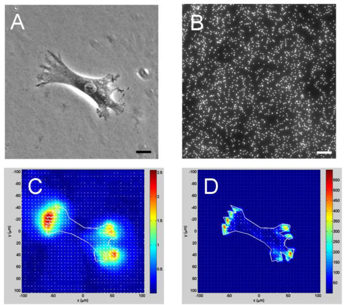
2.2.4. Cell traction force microscopy
One shortcoming of the MFSA technique is that it can only measure CTFs at predetermined, discreet points. A further advancement in CTF measurement is cell traction force microscopy (CTFM), which can determine CTFs in the entire cell spreading area [7,49,57,58] (Figure 5). CTFM represents a combination of experimental and computational approaches for CTF determination. It relies both on optical tracking of fluorescent microbeads embedded in an elastic substrate to determine deformation of substrate and subsequently on elasticity theory to determine CTFs by computation. Therefore, in essence, the elastic substrate in CTFM functions as a “sensor” of substrate deformations produced by CTFs, and the elastic theory is basically used to “convert” the substrate deformations into CTFs.
A general scheme of CTFM is as follows: first, fluorescent microbeads-embedded elastic hydrogels made of polyacrylamide or gelatin [12], or silicone membranes that are surface-coated with fluorescent beads [49], are used as cell culture substrates. When cultured on a gel, cells generate CTFs, deform the gel, and cause the embedded beads which serve as position markers to dislocate. A pair of images of the microbeads, referred to as “force-loaded” and “null-force” images, respectively, is taken using fluorescence microscope. The “force-loaded” image is taken while the adherent cells remain on the gels, whereas the “null-force” image is taken after the cells have been removed. Two steps are involved in deriving CTFs from this pair of images. The first step is to solve an image registration problem in which beads from the two images are matched and thus gel displacement field is derived. By assuming that image intensity change is a result of substrate surface movement caused by CTFs, several approaches have been used for CTF image registration, including particle tracking velocimetry (PTV) [59], particle image velocimetry (PIV) [39,57,59], feature-based registration [60], and correlation-based PTV [59]. The second step is to solve an inverse problem in which CTFs that will give a best match to the corresponding displacement field are computed. By assuming that the gel is thick enough (e.g., >100 μm) to behave like an elastic half space, the application of the analytical Boussinesq solution obtains the discrete loads as an estimate of the traction forces. This can be achieved either by applying an inverse Fourier transform [57] or by solving a general regularized inverse problem [58]. The latter approach is more complicated, but has the advantage of allowing for the incorporation of a priori information such as levels of errors. A new CTFM approach applies effective pattern recognition algorithms in combination with finite element method (FEM) [60]. In this approach, a feature registration scheme is devised to match individual beads from the image pair. Furthermore, the gel is modeled in FEM as a 3-D object with its actual thickness using brick elements. By applying static condensation, FEM obtains CTFs in the form of forces on the surface nodes that lie within the boundary of the cells. This approach ensures reliable displacement calculation and enables simultaneous determination of CTFs of multiple cells.
Based on fluorescence microscopy imaging and computational mechanics, CTFM offers unique advantages over other CTF-sensing techniques in that it can sense and quantify CTFs of a wide range of individual cells or cell aggregates reliably, accurately, and efficiently. For example, the substrate used in CTFM, polyacrylamide gel (PAG), can be easily prepared and is linearly elastic in response to a wide range of stresses, and the deformation is completely recovered upon removal of the stress [61,62]. The stiffness of PAG can be easily adjusted in a broad range from as low as 10 Pa up to as high as 40 kPa [63]. In contrast, similar continuum substrate-based techniques using silicone membranes have been used less frequently, partially because it needs very delicate skill to fabricate ultra-thin membranes that are compliant enough for traction force measurement [4,49,51]. Similarly, a fluorescence resonance energy transfer (FRET)-based technique, which relies on the molecular packing of two fluorescently labeled peptides to indicate matrix deformation, also has only limited applications due to the technical complexity to determine CTFs quantitatively and the difficulty in preparing an optimal substrate containing two fluorophores, despite the fact that it can directly “visualize” the CTFs of a cell by monitoring changes in fluorescent colors [64].
3. Conclusions and Perspectives
Cells use CTFs, the mechanical forces that are generated by cells and transmitted to ECM, to probe their physical environment and to migrate, maintain their shape, and organize the ECM. Therefore, CTFs play a critical role in many fundamental biological processes including embryogenesis, tissue morphogenesis, angiogenesis, inflammation, wound healing, and metastasis. In addition, because perturbation of CTF-related proteins, such as actin, myosin, and focal adhesion proteins (e.g., integrins), of individual cells likely causes changes in CTFs, CTF may be used as a biophysical marker for characterizing phenotypic changes of cells in response to biochemical and biomechanical stimuli.
To date, a variety of techniques have been developed for sensing and quantifying CTFs of cells, either in a cell population as a whole or in individual cells. Among them, MFSA and CTFM represent the most advanced technologies and have since been widely used in CTF measurement. In addition to simple force measurement, such techniques also can be adopted to construct useful in vitro models that may aid in early diagnosis of diseases and screening for cellular and molecular therapies.
While CTF-sensing technologies are effective in many current situations, further advancement in these technologies and their applications should focus on the following aspects. First, improvement in the spatial resolution of force-sensing through both experimental and computational approaches is necessary. The ability to sense CTFs at nano-scale will greatly help bridge and integrate existing knowledge of biomechanics at molecular and cellular levels, respectively. Second, current sensing techniques for CTF measurement are mainly limited to 2-D environments, which are less physiological since cells reside in 3-D tissues in vivo. While attempts have been made in this regard recently [65,66], it is far from satisfactory because such measurements did not truly determine CTFs in a 3-D fashion. Thus, innovative sensing techniques are needed to enable sensing of CTFs in 3-D matrices such that the measured CTFs are more physiologically relevant. Findings from such studies will significantly advance our understanding of cell contractility in relation to normal and disease states. Third, in addition to improved resolution with nano-scale CTF-sensing capability, techniques that enable real time assays and/or combine with molecular biology techniques such as fluorescent protein fusion [49] should be used more extensively to decipher in more depth the molecular mechanisms and dynamics of CTF generation and transmission.
Acknowledgments
The authors would like to thank the financial support from the Start-up Fund of Soochow University (B.L.) and NIH (AR049921, AR049921S1, and AR049921S2) (J.H.W.).
References
- Spudich, JA. The myosin swinging cross-bridge model. Nat. Rev. Mol. Cell Biol 2001, 2, 387–392. [Google Scholar]
- Huxley, HE. The mechanism of muscular contraction. Science 1969, 164, 1356–1365. [Google Scholar]
- Korn, ED; Hammer, JA. Myosins of nonmuscle cells. Annu. Rev. Biophys. Biophys. Chem 1988, 17, 23–45. [Google Scholar]
- Balaban, NQ; Schwarz, US; Riveline, D; Goichberg, P; Tzur, G; Sabanay, I; Mahalu, D; Safran, S; Bershadsky, A; Addadi, L; Geiger, B. Force and focal adhesion assembly: A close relationship studied using elastic micropatterned substrates. Nat. Cell Biol 2001, 3, 466–472. [Google Scholar]
- Burridge, K; Chrzanowska-Wodnicka, M. Focal adhesions, contractility, and signaling. Annu. Rev. Cell Dev. Biol 1996, 12, 463–518. [Google Scholar]
- Harris, AK; Stopak, D; Wild, P. Fibroblast traction as a mechanism for collagen morphogenesis. Nature 1981, 290, 249–251. [Google Scholar]
- Wang, JH; Lin, JS. Cell traction force and measurement methods. Biomech. Model. Mechanobiol 2007, 6, 361–371. [Google Scholar]
- Pourati, J; Maniotis, A; Spiegel, D; Schaffer, JL; Butler, JP; Fredberg, JJ; Ingber, DE; Stamenovic, D; Wang, N. Is cytoskeletal tension a major determinant of cell deformability in adherent endothelial cells? Am. J. Physiol 1998, 274, 1283–1289. [Google Scholar]
- Beningo, KA; Dembo, M; Kaverina, I; Small, JV; Wang, YL. Nascent focal adhesions are responsible for the generation of strong propulsive forces in migrating fibroblasts. J. Cell Biol 2001, 153, 881–888. [Google Scholar]
- Brown, RA; Prajapati, R; McGrouther, DA; Yannas, IV; Eastwood, M. Tensional homeostasis in dermal fibroblasts: Mechanical responses to mechanical loading in three-dimensional substrates. J. Cell Physiol 1998, 175, 323–332. [Google Scholar]
- Eckes, B; Krieg, T. Regulation of connective tissue homeostasis in the skin by mechanical forces. Clin. Exp. Rheumatol 2004, 22, S73–6. [Google Scholar]
- Beningo, KA; Wang, YL. Flexible substrata for the detection of cellular traction forces. Trends Cell Biol 2002, 12, 79–84. [Google Scholar]
- Burton, K; Park, JH; Taylor, DL. Keratocytes generate traction forces in two phases. Mol. Biol. Cell 1999, 10, 3745–3769. [Google Scholar]
- Tranquillo, RT; Durrani, MA; Moon, AG. Tissue engineering science—Consequences of cell traction force. Cytotechnology 1992, 10, 225–250. [Google Scholar]
- Bell, E; Ehrlich, HP; Buttle, DJ; Nakatsuji, T. Living tissue formed in vitro and accepted as skin-equivalent tissue of full thickness. Science 1981, 211, 1052–1054. [Google Scholar]
- Carlson, MA; Longaker, MT. The fibroblast-populated collagen matrix as a model of wound healing: A review of the evidence. Wound Repair Regen 2004, 12, 134–147. [Google Scholar]
- Delvoye, P; Wiliquet, P; Leveque, JL; Nusgens, BV; Lapiere, CM. Measurement of mechanical forces generated by skin fibroblasts embedded in a three-dimensional collagen gel. J. Invest. Dermatol 1991, 97, 898–902. [Google Scholar]
- Brown, RA; Talas, G; Porter, RA; McGrouther, DA; Eastwood, M. Balanced mechanical forces and microtubule contribution to fibroblast contraction. J. Cell Physiol 1996, 169, 439–447. [Google Scholar]
- Eastwood, M; McGrouther, DA; Brown, RA. A culture force monitor for measurement of contraction forces generated in human dermal fibroblast cultures: Evidence for cell-matrix mechanical signalling. Biochim. Biophys. Acta 1994, 1201, 186–192. [Google Scholar]
- Freyman, TM; Yannas, IV; Yokoo, R; Gibson, LJ. Fibroblast contractile force is independent of the stiffness which resists the contraction. Exp. Cell Res 2002, 272, 153–162. [Google Scholar]
- Dallon, JC; Ehrlich, HP. A review of fibroblast-populated collagen lattices. Wound Repair Regen 2008, 16, 472–479. [Google Scholar]
- Grinnell, F. Fibroblasts, myofibroblasts, and wound contraction. J. Cell Biol 1994, 124, 401–404. [Google Scholar]
- Ehrlich, HP; Rajaratnam, JB. Cell locomotion forces versus cell contraction forces for collagen lattice contraction: an in vitro model of wound contraction. Tissue. Cell 1990, 22, 407–417. [Google Scholar]
- Nishiyama, T; Tominaga, N; Nakajima, K; Hayashi, T. Quantitative evaluation of the factors affecting the process of fibroblast-mediated collagen gel contraction by separating the process into three phases. Coll. Relat. Res 1988, 8, 259–73. [Google Scholar]
- Qi, J; Chi, L; Wang, J; Sumanasinghe, R; Wall, M; Tsuzaki, M; Banes, AJ. Modulation of collagen gel compaction by extracellular ATP is MAPK and NF-kappaB pathways dependent. Exp. Cell. Res 2009, 315, 1990–2000. [Google Scholar]
- Harley, BA; Freyman, TM; Wong, MQ; Gibson, LJ. A new technique for calculating individual dermal fibroblast contractile forces generated within collagen-GAG scaffolds. Biophys. J 2007, 93, 2911–2922. [Google Scholar]
- Kasugai, S; Suzuki, S; Shibata, S; Yasui, S; Amano, H; Ogura, H. Measurements of the isometric contractile forces generated by dog periodontal ligament fibroblasts in vitro. Arch. Oral. Biol 1990, 35, 597–601. [Google Scholar]
- Kolodney, MS; Wysolmerski, RB. Isometric contraction by fibroblasts and endothelial cells in tissue culture: a quantitative study. J. Cell. Biol 1992, 117, 73–82. [Google Scholar]
- Dahlmann-Noor, AH; Martin-Martin, B; Eastwood, M; Khaw, PT; Bailly, M. Dynamic protrusive cell behaviour generates force and drives early matrix contraction by fibroblasts. Exp. Cell Res 2007, 313, 4158–4169. [Google Scholar]
- Eastwood, M; Porter, R; Khan, U; McGrouther, G; Brown, R. Quantitative analysis of collagen gel contractile forces generated by dermal fibroblasts and the relationship to cell morphology. J. Cell. Physiol 1996, 166, 33–42. [Google Scholar]
- Campbell, BH; Agarwal, C; Wang, JH. TGF-beta1, TGF-beta3, and PGE(2) regulate contraction of human patellar tendon fibroblasts. Biomech. Model. Mechanobiol 2004, 2, 239–45. [Google Scholar]
- Campbell, BH; Clark, WW; Wang, JH. A multi-station culture force monitor system to study cellular contractility. J. Biomech 2003, 36, 137–140. [Google Scholar]
- Peperzak, KA; Gilbert, TW; Wang, JH. A multi-station dynamic-culture force monitor system to study cell mechanobiology. Med. Eng. Phys 2004, 26, 355–358. [Google Scholar]
- Bogatkevich, GS; Tourkina, E; Abrams, CS; Harley, RA; Silver, RM; Ludwicka-Bradley, A. Contractile activity and smooth muscle alpha-actin organization in thrombin-induced human lung myofibroblasts. Am. J. Physiol. Lung Cell Mol. Physiol 2003, 285, L334–343. [Google Scholar]
- Ferrenq, I; Tranqui, L; Vailhe, B; Gumery, PY; Tracqui, P. Modelling biological gel contraction by cells: mechanocellular formulation and cell traction force quantification. Acta Biotheor 1997, 45, 267–93. [Google Scholar]
- Harris, AK; Wild, P; Stopak, D. Silicone rubber substrata: A new wrinkle in the study of cell locomotion. Science 1980, 208, 177–179. [Google Scholar]
- Oliver, T; Dembo, M; Jacobson, K. Traction forces in locomoting cells. Cell. Motil. Cytoskeleton 1995, 31, 225–240. [Google Scholar]
- Beningo, KA; Lo, CM; Wang, YL. Flexible polyacrylamide substrata for the analysis of mechanical interactions at cell-substratum adhesions. Methods. Cell. Biol 2002, 69, 325–339. [Google Scholar]
- Dembo, M; Wang, YL. Stresses at the cell-to-substrate interface during locomotion of fibroblasts. Biophys. J 1999, 76, 2307–2316. [Google Scholar]
- Wang, N; Ostuni, E; Whitesides, GM; Ingber, DE. Micropatterning tractional forces in living cells. Cell. Motil. Cytoskeleton 2002, 52, 97–106. [Google Scholar]
- Galbraith, CG; Sheetz, MP. A micromachined device provides a new bend on fibroblast traction forces. Proc. Natl. Acad. Sci. USA 1997, 94, 9114–9118. [Google Scholar]
- Li, B; Xie, L; Starr, ZC; Yang, Z; Lin, JS; Wang, JH. Development of micropost force sensor array with culture experiments for determination of cell traction forces. Cell. Motil. Cytoskeleton 2007, 64, 509–518. [Google Scholar]
- Tan, JL; Tien, J; Pirone, DM; Gray, DS; Bhadriraju, K; Chen, CS. Cells lying on a bed of microneedles: an approach to isolate mechanical force. Proc. Natl. Acad. Sci. USA 2003, 100, 1484–1489. [Google Scholar]
- du Roure, O; Saez, A; Buguin, A; Austin, RH; Chavrier, P; Silberzan, P; Ladoux, B. Force mapping in epithelial cell migration. Proc. Natl. Acad. Sci. USA 2005, 102, 2390–5. [Google Scholar]
- Lemmon, CA; Chen, CS; Romer, LH. Cell traction forces direct fibronectin matrix assembly. Biophys. J 2009, 96, 729–738. [Google Scholar]
- Zhao, Y; Zhang, X. Adaptation of flexible polymer fabrication to cellular mechanics study. Appl. Phys. Lett 2005, 87, 144101. [Google Scholar]
- Burton, K; Taylor, DL. Traction forces of cytokinesis measured with optically modified elastic substrata. Nature 1997, 385, 450–454. [Google Scholar]
- Lee, J; Leonard, M; Oliver, T; Ishihara, A; Jacobson, K. Traction forces generated by locomoting keratocytes. J. Cell Biol 1994, 127, 1957–64. [Google Scholar]
- Iwadate, Y; Yumura, S. Actin-based propulsive forces and myosin-II-based contractile forces in migrating Dictyostelium cells. J. Cell Sci 2008, 121, 1314–1324. [Google Scholar]
- Schwarz, US; Balaban, NQ; Riveline, D; Bershadsky, A; Geiger, B; Safran, SA. Calculation of forces at focal adhesions from elastic substrate data: The effect of localized force and the need for regularization. Biophys. J 2002, 83, 1380–1394. [Google Scholar]
- Das, T; Maiti, TK; Chakraborty, S. Traction force microscopy on-chip: shear deformation of fibroblast cells. Lab Chip 2008, 8, 1308–1318. [Google Scholar]
- Tan, W; Desai, TA. Microscale multilayer cocultures for biomimetic blood vessels. J. Biomed. Mater. Res. Part A 2005, 72A, 146–160. [Google Scholar]
- Zheng, XY; Zhang, X. An optical Moire technique for cell traction force mapping. J. Micromech. Microeng 2008, 18, 125006. [Google Scholar]
- Timoshenko, S; Woinowskey-Kreiger, S. Theory of Plates and Shells; McGraw-Hill: New York, NY, USA, 1959. [Google Scholar]
- Tymchenko, N; Wallentin, J; Petronis, S; Bjursten, LM; Kasemo, B; Gold, J. A novel cell force sensor for quantification of traction during cell spreading and contact guidance. Biophys. J 2007, 93, 335–45. [Google Scholar]
- Sniadecki, NJ; Lamb, CM; Liu, Y; Chen, CS; Reich, DH. Magnetic microposts for mechanical stimulation of biological cells: fabrication, characterization, and analysis. Rev. Sci. Instrum 2008, 79, 044302. [Google Scholar]
- Butler, JP; Tolic-Norrelykke, IM; Fabry, B; Fredberg, JJ. Traction fields, moments, and strain energy that cells exert on their surroundings. Am. J. Physiol. Cell Physiol 2002, 282, 595–605. [Google Scholar]
- Dembo, M; Oliver, T; Ishihara, A; Jacobson, K. Imaging the traction stresses exerted by locomoting cells with the elastic substratum method. Biophys. J 1996, 70, 2008–2022. [Google Scholar]
- Sabass, B; Gardel, ML; Waterman, CM; Schwarz, US. High resolution traction force microscopy based on experimental and computational advances. Biophys. J 2008, 94, 207–20. [Google Scholar]
- Yang, Z; Lin, JS; Chen, J; Wang, JH. Determining substrate displacement and cell traction fields—A new approach. J. Theor. Biol 2006, 242, 607–616. [Google Scholar]
- Pelham, RJ, Jr; Wang, Y. Cell locomotion and focal adhesions are regulated by substrate flexibility. Proc. Natl. Acad. Sci. USA 1997, 94, 13661–13665. [Google Scholar]
- Wang, YL; Pelham, RJ, Jr. Preparation of a flexible, porous polyacrylamide substrate for mechanical studies of cultured cells. Methods Enzymol 1998, 298, 489–496. [Google Scholar]
- Yeung, T; Georges, PC; Flanagan, LA; Marg, B; Ortiz, M; Funaki, M; Zahir, N; Ming, W; Weaver, V; Janmey, PA. Effects of substrate stiffness on cell morphology, cytoskeletal structure, and adhesion. Cell Motil. Cytoskeleton 2005, 60, 24–34. [Google Scholar]
- Kong, HJ; Polte, TR; Alsberg, E; Mooney, DJ. FRET measurements of cell-traction forces and nano-scale clustering of adhesion ligands varied by substrate stiffness. Proc. Natl. Acad. Sci. USA 2005, 102, 4300–4305. [Google Scholar]
- Hur, SS; Zhao, Y; Li, YS; Botvinick, E; Chien, S. Live cells exert 3-dimensional traction forces on their substrata. Cell. Mole. Bioeng 2009, 2, 425–436. [Google Scholar]
- Mierke, CT; Rosel, D; Fabry, B; Brabek, J. Contractile forces in tumor cell migration. Eur. J. Cell Biol 2008, 87, 669–676. [Google Scholar]


© 2010 by the authors; licensee MDPI, Basel, Switzerland. This article is an open access article distributed under the terms and conditions of the Creative Commons Attribution license (http://creativecommons.org/licenses/by/3.0/.)
Share and Cite
Li, B.; Wang, J.H.-C. Application of Sensing Techniques to Cellular Force Measurement. Sensors 2010, 10, 9948-9962. https://doi.org/10.3390/s101109948
Li B, Wang JH-C. Application of Sensing Techniques to Cellular Force Measurement. Sensors. 2010; 10(11):9948-9962. https://doi.org/10.3390/s101109948
Chicago/Turabian StyleLi, Bin, and James H.-C. Wang. 2010. "Application of Sensing Techniques to Cellular Force Measurement" Sensors 10, no. 11: 9948-9962. https://doi.org/10.3390/s101109948