Communication

High Sensitivity Carbon Nanotubes Flow-Rate Sensors and Their Performance Improvement by Coating

1
MEMS Lab, Department of Precision Instruments & Mechanology, Tsinghua University, 100084, Beijing, China
2
State Key Lab of Precision Measurement Technology and Instrumentation, Tsinghua University, 100084, Beijing, China
*
Author to whom correspondence should be addressed.
Sensors 2010, 10(5), 4898-4906; https://doi.org/10.3390/s100504898
Submission received: 26 March 2010 / Revised: 17 April 2010 / Accepted: 25 April 2010 / Published: 14 May 2010
(This article belongs to the Section Chemical Sensors)

Abstract

:
A new type of hot-wire flow-rate sensor (HWFS) with a sensing element made of a macro-sized carbon nanotube (CNT) strand is presented in this study. An effective way to improve repeatability of the CNT flow-rate sensor by coating a layer of Al2O3 on the CNT surface is proposed. Experimental results show that due to the large surface-to-volume ratio and thin coated Al2O3 layer, the CNT flow-rate sensor has higher sensitivity and faster response than a conventional platinum (Pt) HWFS. It is also demonstrated that the covered CNT flow-rate sensor has better repeatability than its bare counterpart due to insulation from the surrounding environment. The proposed CNT flow-rate sensor shows application potential for high-sensitivity measurement of flow rate.

Graphical Abstract

1. Introduction

Hot-wire (or hot-film) flow-rate sensors, with their wide application in fluid mechanics measurements, are predominantly used for measurement in low-velocity flow or low turbulence flow. HWFS is characterized by high spatial and time resolution, high frequency band, low background noise, simple apparatus, and low cost. With the recent developments of micro-fluid, microelectromechanical systems (MEMS), and the lab-on-a-chip, a HWFS is now required to accommodate higher sensitivity for fluid mechanics measurement in small scale. According to the principles (convective heat transfer), HWFS should have a large surface-to-volume (S/V) ratio, large temperature coefficient of resistance (TCR), and large slenderness ratio to improve their sensitivity. As a novel material, CNTs have exhibited excellent sensing properties [1], which have been utilized forgas sensor [24], temperature [5,6] and humidity sensors [7,8], pressure sensor [9,10], chemical sensor [11,12], biosensor [13,14], and flow sensor [15,16]. In relation to CNTs-HWFS, Victor et al. [15] proposed a bulk multi-walled carbon nanotube (MWCNT) element for anemometry sensors and discovered that it could be operated with very low power consumption (μW). Ghosh et al. [16] reported that the flow of a liquid on single-walled CNT bundles could induce a voltage that fits the logarithmic relation of velocity in the fluid. Their works showed the device’s potential for nanotubes as sensitive flow sensors. In recent years, macro-sized CNT strands (MSCNTS) composed of many individual CNTs at centimeter lengths were synthesized [1719], which should very suit HWFS due to their large S/V ratio and large slenderness. Other advantages of MSCNTS flow sensors include high mechanical strength and low cost.
In this paper, a MSCNTS-HWFS is proposed, which demonstrates higher sensitivity and faster response than conventional Pt HWFS. To improve MSCNTS-HWFS performance, a thin oxide layer is deposited on the CNTs’ surface in the MSCNTS. The coated MSCNTS-HWFS shows better stability and repeatability than the bare counterpart.

2. Analysis and Design

HWFS is based on convective heat transfer from a heated wire or film element placed in a fluid flow [2022]. Fluid velocity is measured by sensing changes in heat transfer from an electrically heated hot-wire exposed to the fluid. HWFS can be operated in different modes, wherein the two most important modes are constant current (CC) mode and constant temperature (CT) mode [21]. In constant current dissipation, the temperature of a heated hot-wire decreases with the increasing of the fluid’s flow velocity. In steady state, the heat balance equation for the HWFS is given by (1) [21,23]:
Q J = Q C + Q FC + Q R
where QJ is the generated power from Joule heating; QC is the sum of conductive losses involving (1) end loss of the support prongs and (2) longitudinal thermal conduction along the hot-wire; QFC is the heat loss due to forced convection; and QR is the heat loss due to the heat radiation, which can be ignored when the temperature of the hot-wire is below 300 °C.
If conductive losses and heat radiation loss are ignored, from Equation (1), Joule law, heat-transfer and hot-wire anemometer theories, the cylindrical hot-wire should have the following equation [21,23]:
Q FC = I w 2 · R w π dlh ( U ) ( T w , T f ) [ 1 2 l c l tanh ( l 2 l c ) ]
where d and l are the diameter and the length of the hot-wire, respectively; Iw and Rw are current and resistance of hot-wire; Tw, ∞ is the temperature of the similar infinitely long hot-wire heated by a current Iw; Tf is the temperature of the fluid; lc is the “cold length” whose detail definition could be found in reference [21]; h(U) is the overall heat transfer coefficient which is related to the flow velocity U [23]:
h ( U ) = A + B U n
where n is a fitting factor that depends on hot-wire geometry; A accounts for the natural convection as well as the conduction end loss, and BUn is the forced convection term.
In CC-mode, the flow rate is measured by monitoring the voltage of the MSCNTS-HWFS and we have:
V w = π dl ( A + B · U n ) ( T w , T f ) [ 1 2 l c l tanh ( l 2 l c ) ] I w
From Equation (4), we know that under a given current, there is a definite relationship between U and Vw. Differentiating Equation (4):
d V w d U = π dl ( T w , T f ) [ 1 2 l c l tanh ( l 2 l c ) ] I w · n · B · U n 1
Parameter B can be experientially expressed as [20]:
B = 0.57 kA s d ( μ C p k ) 0.33 ( ρ d k ) 0.5 = 0.57 k · π d · l d 0.5 ( μ C p k ) 0.33 ( ρ k ) 0.5 = 0.57 k · π d 0.5 · l ( μ C p k ) 0.33 ( ρ k ) 0.5
where k, μ and ρ are the thermal conductivity, the dynamic viscosity and the density of the fluid, respectively; Cp is the specific heat of the fluid at constant pressure; As is surface area of the wire.
From Equation (5), we know that we should maximize dVw/dU for obtaining the large sensitivity. Assume that the diameters and resistance of the traditional metal hot-wire and the MSCNTS hot-wire are equal. And assume that MSCNTS hot-wire is consist of many individual CNTs with diameters of d/m, the number of CNTs in the strand is about m2. From Equation (6), if the power is the same, the B of the MSCNT is:
B = m 2 · 0.57 k · π ( d m ) 0.5 · l ( μ C p k ) 0.33 ( ρ k ) 0.5 = m 1.5 · 0.57 k · π d 0.5 · l ( μ C p k ) 0.33 ( ρ k ) 0.5
From equations (6) and (7), the B of the MSCNT is about m1.5 times larger than that of the metal hot-wire with the same diameter. According to the analysis, high sensitivity of the MSCNTS-HWFS is mainly due to the large S/V ratio of the macro-sized CNT strand.

3. Experimental Details
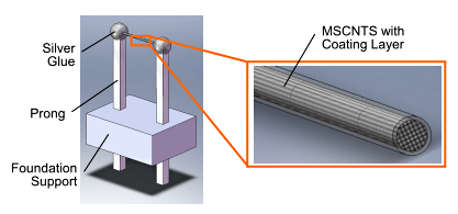
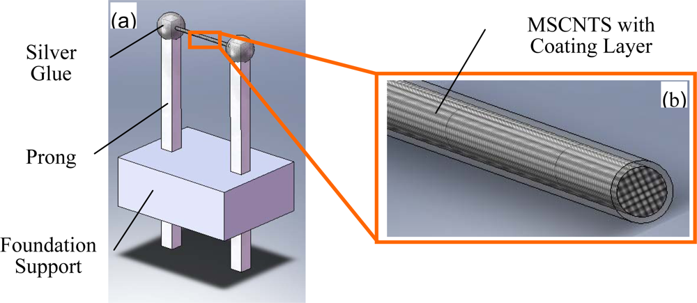
3.1. Fabrication

The centimeter-long strands of MSCNTS used in our experiments are synthesized by the catalytic chemical vapor deposition (CVD) method. The CNTs in the MSCNTS are mainly multi-walled, with diameters ranging from 5 nm to 30 nm and lengths of more than 4 millimeters.
The specific fabrication steps of the MSCNTS-HWFS include:
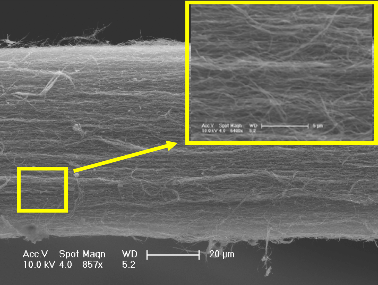
  • A thin MSCNTS with diameters of about tens of micrometers are pulled out from a thick as-grown MSCNTS using precise tweezers;
  • Then the MSCNTS is suspended straightly between the two 4.4 mm-spacing metal prongs;
  • A drop of conducting adhesive is dripped on each contact area and is dried under 120 °C heating conditions for 2 hours for fixing the two ends of the strand and improving the contact characteristics.
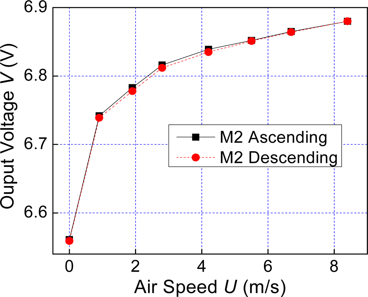
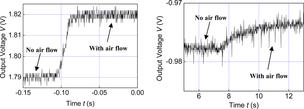
Figure 1a is a schematic diagram of the MSCNTS flow-rate sensor and Figure 1b is the enlarged view of the MSCNTS which shows the MSCNTS is composed of many individual CNTs (the MSCNTS was cut off for showing its cross-section).
Aluminum oxide (Al2O3) is known to have good thermal conductivity and insulating property. To reduce the disturbance by the surrounding environment, the surface of the MSCNTS is deposited with a layer of Al2O3 via the magnetron sputtering. The thickness of the Al2O3 layer can be controlled by sputtering time. Figure 2 shows the MSCNTS’s scanning electron microscope (SEM) images where 50 nm Al2O3 is uniformly sputtered on the MSCNTS surface. Inset in Figure 2b is the EDS (Energy dispersive x-ray spectroscopy) analysis of the MSCNTS coated with a layer of Al2O3, which demonstrates that the Al2O3 has been coated on the MSCNTS’s surface.

3.2. Measurements

We firstly tested the steady-state performance of the MSCNTS-HWFS in a wind tunnel where maximum air velocity was about 15 m/s, which was calibrated by a commercial HWFS to guarantee measurement accuracy. The fabricated MSCNTS-HWFS was operated in constant-current (CC) mode: a constant-current source applies a constant current on the MSCNTS, and the voltage drop of the MSCNTS-HWFS was recorded at different air velocity conditions. Although the resistance values of each MSCNTS-HWFS and Pt100 (reference commercial HWFS) were different, they retained the same power (0.01 W) in the comparable measurement. Figure 3a shows the steady-state response curves of the MSCNTS-HWFS at different air velocities wherein the CNT surface is bare.
Figure 3b shows the steady-state response curves of Pt100 at different air velocities. In CC mode, the sensitivity S of the HWFS can be defined as follows:
S = V max V 0 V 0
where Vmax and V0 are the output voltage at zero and maximum air velocities, respectively. According to Equation (8) and experimental curves, the bare MSCNTS-HWFS is more sensitive than the Pt100, in which the calculated sensitivities are 3.38% and 2.13%, respectively. However, the bare MSCNTS-HWFS has more hysterisis than Pt100, and the hysterisis errors are 8.23% and 4.35%, respectively.
This study also measured the response curves of the MSCNTS-HWFS coated with a layer of Al2O3. Figure 4 reveals an improvement in the curves’ repeatability at the covered MSCNTS-HWFS. The hysterisis error is reduced to 1.56%. The sensitivity of the covered MSCNTS-HWFS improves slightly (the value is 4.24%) based on the calculations.
We further tested the dynamic response of the coated MSCNTS-HWFS. The time responses under 8.5 m/s flow velocity were recorded as shown in Figure 5 by the withdrawing baffle plate method for producing the air flow step (both MSCNTS-HWFS and Pt100 work at a power of 0.01 W). As shown in Figure 5 the response time of MSCNTS-HWFS is about tens of microseconds, which is faster than that of the Pt100 (about several seconds).
We also measured the sensitivity of another MSCNTS-HWFS (sample 2#) where the MWCNTs in the strand have larger average diameter (about 50 nm) than that in the MWCNTS (sample 1#), shown in Figure 2. Figure 6 shows the SEM images of sample 2# which show that sample 2# has a looser structure than that of sample 1#. The sensitivity measurement results show that sample 2# has lower sensitivity than that of the sample 1#, which proves sample 1# has a larger S/V ratio than that of sample 2# due to the smaller average diameter of MWCNT in sample 1#. The experimental results and the SEM images also demonstrate the loose structure in the MSCNTS has better heat transfer than that of the compact structure in the MSCNTS.
The theoretical analysis and experiments prove that MSCNTS-HWFS has higher sensitivity than conventional Pt HWFS due to the large S/V ratio of the MSCNTS. It is also found that it effectively improves repeatability and reduces hysterisis error via the coating of the Al2O3 layer on the CNT surface. The reason may be that the covered CNTs are not easily disturbed by the surrounding environment and the heat could be transferred through the covered layer with high thermal conductivity. Because circumjacent humidity and gas don’t influence the resistance of the MSCNTS coated with Al2O3, the stability of the covered MSCNTS-HWFS is improved. The experimental curves also show that the MSCNTS-HWFS has higher sensitivity in low air speed range, which suits for low-speed precision measurement. The coated Al2O3 layer on the CNT surface is very thin, so MSCNTS-HWFS also has fast dynamic response.

4. Conclusions

We have developed a MSCNTS-HWFS characterized by higher sensitivity and faster response compared to the conventional Pt HWFS. We also propose an effective way to improve the repeatability of the MSCNTS-HWFS by coating a layer of Al2O3 on the CNT surface. Formulas and analysis are provided to explain the experimental results. MSCNTS-HWFS shows the application potential for high-sensitivity measurement of air velocity or flow rate, which can be also used for high-sensitivity measurement of fluid due to the covered insulating layer.

Acknowledgments

The authors would like to thank J. Liang and J. Q. Wei (Department of Mechanical Engineering, Tsinghua University) for their helps for providing CNT samples. This work is supported by the National Natural Science Foundation of China (NSFC) through Grant No. 50875139 and No. 10832005.

References

  1. Benjamin, M.; Cosmin, L.; Ronnie, Y.; Yun, S. Development of carbon nanotube-based sensors—A review. IEEE Sens. J 2007, 7, 266–284. [Google Scholar]
  2. Collins, P.G.; Bradley, K.; Ishigami, M.; Zettl, A. Extreme oxygen sensitivity of electronic properties of carbon nanotubes. Science 2000, 287, 1801–1804. [Google Scholar]
  3. Li, J.; Lu, Y.J.; Ye, Q.; Cinke, M.; Han, J.; Meyyappan, M. Carbon nanotube sensors for gas and organic vapor detection. Nano Lett 2003, 3, 929–933. [Google Scholar]
  4. Keat, G.O; Craig, A.G. A carbon nanotube-based sensor for CO2 monitoring. Sensors 2001, 1, 193–205. [Google Scholar]
  5. Gao, Y.H.; Bando, Y.; Liu, Z.W.; Golberg, D. Temperature measurement using a gallium-filled carbon nanotube nanothermometer. Appl. Phys. Lett 2003, 83, 2913–2915. [Google Scholar]
  6. Mahanandia, P.; Singh, L.T.; Nanda, K.K. Possible application of carbon nanotube bundles for low temperature sensing. Rev. Sci. Instrum 2008, 79, 053909-1–053909-5. [Google Scholar]
  7. Liu, L.T.; Ye, X.Y.; Wu, K.; Han, R.; Zhou, Z.Y.; Cui, T.H. Humidity sensitivity of multi-walled carbon nanotube networks deposited by dielectrophoresis. Sensors 2009, 9, 1714–1721. [Google Scholar]
  8. Zhang, Y.S.; Yu, K.; Xu, R.L.; Jiang, D.S.; Luo, L.Q.; Zhu, Z.Q. Quartz crystal microbalance coated with carbon nanotube films used as humidity sensor. Sens. Actuat. A 2005, 120, 142–146. [Google Scholar]
  9. Li, C.Y.; Chou, T.W. Strain and pressure sensing using single-walled carbon nanotubes. Nanotechnology 2004, 15, 1493–1496. [Google Scholar]
  10. Stampfer, C.; Helbling, T.; Obergfell, D.; Schöberle, B.; Tripp, M.K.; Jungen, A.; Roth, S.; Bright, V.M.; Hierold, C. Fabrication of single-walled carbon-nanotube-based pressure sensors. Nano Lett 2006, 6, 233–237. [Google Scholar]
  11. Shah, R.A.; Rishi, R.P.; Yetunde, B.; Yufeng, M.; Huixin, H. A nonoxidative electrochemical sensor based on a self-doped polyaniline/carbon nanotube composite for sensitive and selective detection of the neurotransmitter dopamine: a review. Sensors 2008, 8, 8423–8452. [Google Scholar]
  12. Wu, J.; Liu, H.X.; Lin, Z.D. Electrochemical performance of a carbon nanotube/La-doped TiO2 nanocomposite and its use for preparation of an electrochemical nicotinic acid sensor. Sensors 2008, 8, 7085–7096. [Google Scholar]
  13. Sofia, S.; Nikolas, A.C. Carbon nanotube array-based biosensor. Anal. Bioanal. Chem 2003, 375, 103–105. [Google Scholar]
  14. Kenzo, M.; Kazuhiko, M. Label-free electrical detection using carbon nanotube-based biosensors. Sensors 2009, 9, 5368–5378. [Google Scholar]
  15. Victor, T.S.; Wen, J.L. Bulk carbon nanotubes as sensing element for temperature and anemometry micro sensing. Proceedings of IEEE MEMS Conference 2003, Kyoto, Japan, January 2003; pp. 41–44.
  16. Ghosh, S.; Sood, A.K.; Kumar, N. Carbon nanotube flow sensors. Science 2003, 299, 1042–1044. [Google Scholar]
  17. Wei, J.Q.; Jiang, B.; Wu, D.H.; Wei, B.Q. Large scale synthesis of long double-walled carbon nanotubes. J. Phys. Chem. B 2004, 108, 8844–8847. [Google Scholar]
  18. Pan, Z.W.; Xie, S.S.; Lu, L.; Chang, B.H.; Sun, L.F.; Zhou, W.Y.; Wang, G.; Zhang, D.L. Tensile tests of ropes of very long aligned multiwall carbon nanotubes. Appl. Phys. Lett 1999, 74, 3152–3154. [Google Scholar]
  19. Zhu, L.B.; Xu, J.W.; Xiu, Y.H.; Sun, Y.Y.; Hessa, D.W.; Wong, C.P. Growth and electrical characterization of high-aspect-ratio carbon nanotube arrays. Carbon 2006, 44, 253–258. [Google Scholar]
  20. Perry, A.E. Hot-wire Anemometer; Oxford University Press: New York, NY, USA, 1982; pp. 19–29. [Google Scholar]
  21. Bruun, H.H. Hot Wire Anemometry: Principles and Signal Analysis; Oxford University Press: New York, NY, USA, 1995; pp. 7–26. [Google Scholar]
  22. Zhou, Z.Y.; Li, R.X. Fundamentals of Temperature and Fluid Measurement, 1st ed; Tsinghua University Press: Beijing, China, 1986; pp. 377–386. [Google Scholar]
  23. Jack, C.; Chang, L. Development and characterization of surface micromachined, out-of-plane hot-wire anemometer. J. Microelec. Syst 2003, 12, 979–988. [Google Scholar]
Figure 1. (a) Schematic diagram of the MSCNTS flow-rate sensor and (b) the enlarged view of the MSCNTS which shows the MSCNTS is composed of many individual CNTs (the MSCNTS was cut off for showing its cross-section).
Sensors 10 04898f1
Figure 2. (a) MSCNTS’s SEM images wherein 50 nm Al2O3 is sputtered on the MSCNTS’s surface and (b) the enlarged view of the SEM images where inset is the EDS analysis of the MSCNTS coated with a layer of Al2O3.
Sensors 10 04898f2
Figure 3. (a) Response curves of the bare MSCNTS-HWFS and (b) response curves of the Pt100.
Sensors 10 04898f3
Figure 4. Response curves of the covered MSCNTS-HWFS.
Sensors 10 04898f4
Figure 5. (a) Time response curve of the coated MSCNTS-HWFS and (b) time response curve of the Pt100.
Sensors 10 04898f5
Figure 6. SEM images of MSCNTS (sample 2#).
Sensors 10 04898f6

