Robust and Cooperative Image-Based Visual Servoing System Using a Redundant Architecture

 , ,
, ,
Abstract
: The reliability and robustness of image-based visual servoing systems is still unsolved by the moment. In order to address this issue, a redundant and cooperative 2D visual servoing system based on the information provided by two cameras in eye-in-hand/eye-to-hand configurations is proposed. Its control law has been defined to assure that the whole system is stable if each subsystem is stable and to allow avoiding typical problems of image-based visual servoing systems like task singularities, features extraction errors, disappearance of image features, local minima, etc. Experimental results with an industrial robot manipulator based on Schunk modular motors to demonstrate the stability, performance and robustness of the proposed system are presented.
1. Introduction
Visual servoing is a well known solution to control the position and motion of an industrial manipulator evolved in unstructured environments. The vision-based control laws can be grouped in different approaches based on the definition of the error function and the structure of the control architecture [1–3]. The two classical approaches are know as image-based visual servoing (IBVS) and position-based visual servoing (PBVS). In IBVS, the vision sensor is considered as a two-dimensional (2-D) sensor since the features are directly computed in the image space. This characteristic allows IBVS to be robust to errors in calibration and image noise. However, IBVS has some well-known drawbacks: (1) singularities in the interaction matrix or image Jacobian leading to an unstable behavior; (2) reaching local minima due to the existence of unrealizable image motions; (3) unpredictable 3D camera motion, often suboptimal cartesian and image trajectories violating some constraints of visual servoing techniques as: keeping the object in the field of view; occlusion of target due to obstacles, robot body, or self-occlusion; reaching robot joint limits and singularities in robot Jacobian; collision with obstacles or self-collision. Path planning in the image space is an elegant solution to address IBVS drawbacks. Path planning has been reported in different research papers by exploiting repulsive potential fields [4], screw-motion trajectories [5], interpolation of the collineation matrix [6], modulation of the control gains [7], polynomial parametrizations [8], and search trees in camera and joint spaces [9], parametrizing a family of admissible reference trajectories [10]. When several constraints (visibility, robot mechanical limits, etc.) are simultaneously considered by a path planning scheme, the camera trajectory is deviated from the optimal one. Researchers has concentrated their effort in solving some of the drawbacks of IBVS techniques, e.g., visibility constraint received a particular attention in recent past [11–14], detection and rejection of outliers based on M-estimator based statistical approach that utilizes redundancy in image features [15], an algorithm voting and consensus technique to integrate multiple visual cues to provide a robust input to the control law [16], local estimation through training of the image Jacobian which can handle non-Gaussian outliers due to illumination changes[17], robustness of 2D Visual Servoing in the presence of uncertainties in the 3D Structure [18], etc.
The work presented in this paper is based on our previous works [19,20]. This paper presents a robust visual servoing based on a redundant and cooperative 2D visual servoing system to solve its typical problems like task singularities, features extraction errors, disappearance of image features, etc. is presented. The proposed system is based on the information provided by two cameras in eye-in-hand/eye-to-hand configurations to control the 6 dof of an industrial robot manipulator.
The first approximation about the use of two cameras in eye-in-hand/eye-to-hand configurations was presented in the work of Marchand and Hager [21]. The system described in [21] use two tasks which are controlled by a camera mounted on the robot and a global camera to avoid obstacles during a 3D task. Then, in the paper reported by Flandin et al. [22] a system which integrates a fixed camera and a camera mounted on the robot end-effector is presented. One task is used to control the translation degrees of freedom (dof) of the robot with the fixed camera while other task is used to control the eye-in-hand camera orientation. Contrary to the two works commented before, in this paper, the proposed redundant image-based visual control can control all the 6 dof of the robot with one of the two cameras or with both at the same time in a cooperative way.
The paper is organized as follows. In Section 2, the control architecture of the cooperative image-based visual servoing system is presented. Then, some experimental results of this control scheme with an industrial robot are shown in Section 3. In the last section, the conclusions of this work are summarized.
2. Cooperative Eye-in-Hand/Eye-to-Hand System
Combining several sensory data is also an important issue that has been studied considering two fundamentally different approaches. In the first one, the different sensors are considered to complementary measure of the same physical phenomena. Thus, a sensory data fusion strategy is used to extract the information from multiple sensory data. The second control approach consists of selecting, among the available sensory signals, a set of pertinent data, which is then servoed. The two approaches will be referred as sensory data fusion and sensory data selection respectively.
A typical example of sensory data fusion is stereo vision. With this approach, two images provided by two different cameras are used to extract a complete Euclidean information on the observed scene. On the other hand, sensory data selection is used when all the different data no provide the same quality of information. In this case one can use data environment models in order to select the appropriate sensor and to switch control between sensors.
The approach to cooperative eye-in-hand/eye-to-hand configuration shown in this paper is clearly a case of multi sensory robot control [23]. It is considered as sensory data fusion because we assume that the sensors may observe different physical phenomena from which extracting a single fused information does not make sense. It neither pertains to sensory data selection because we consider potential situations for which it is not possible to select a set of data that would be more pertinent than others. Consequently, the proposed approach addresses a very large spectrum of potential applications, for which the sensory equipment could be extremely complex. As an improvement over previous approaches, there is no need to provide a model of the environment that would be required to design a switching or fusion strategy.
2.1. Controller Design
In this section the design of a redundant and cooperative image-based visual servoing controller is presented. This controller is based on the visual information provided by two cameras located respectively in eye-in-hand and eye-to-hand configurations.
The robot is supposed to be controlled by a six dimensional vector TE representing the end-effector velocity, whose components are supposed to be expressed in the end-effector frame. There are two cameras, one of them rigidly mounted on the robot end-effector (eye-in-hand configuration) and the other one observing the robot gripper (eye-to-hand configuration). Each sensor provides an ni dimensional vector signal si where ni > 6 to be able to control the 6 dof of the robot with any one of the cameras or with the two cameras at the same time in a cooperative way. Let s = [sEIH sETH]T be the vector containing the signals provided by the two sensors. Using the task function formalism [24], a total error function e = C(s − s*) can be defined as:
An interaction matrix is attached to each sensor, such that:
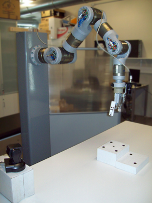
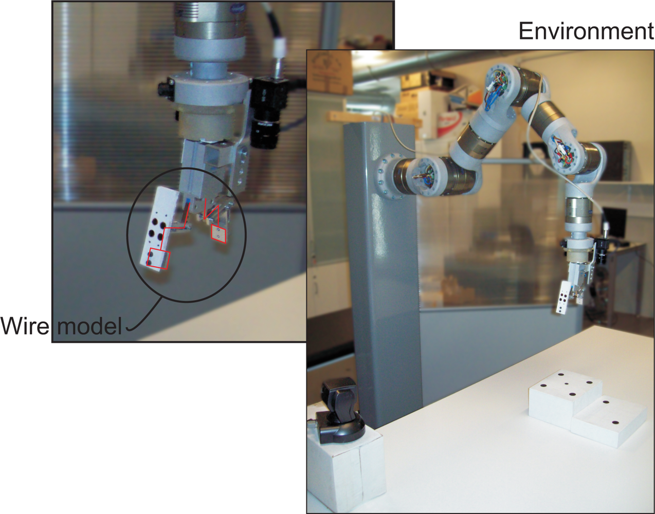
To compute both LETH and TCEETH, the mapping from the camera frame onto the robot control frame (R, t) must be estimated. In this paper, a model based pose estimation algorithm is used since the model of the robot gripper is a priori known [25]. To show the accuracy of the pose estimation, a wire model of the robot gripper is drawn at each iteration of the control law (Figure 1).
The time derivative of the task function (1), considering C and s* constant, is:
If a task function for each sensor (where i = 1 is referred to eye-in-hand configuration and i = 2 to eye-to-hand configuration) is considered, then the task function of the entire system is a weighted sum of the task functions relative to each sensor:
A simple control law can be obtained by imposing the exponential convergence of the task function to zero:
Finally, substituting (4) in (7), the control law to drive back the robot to the reference position is obtained:
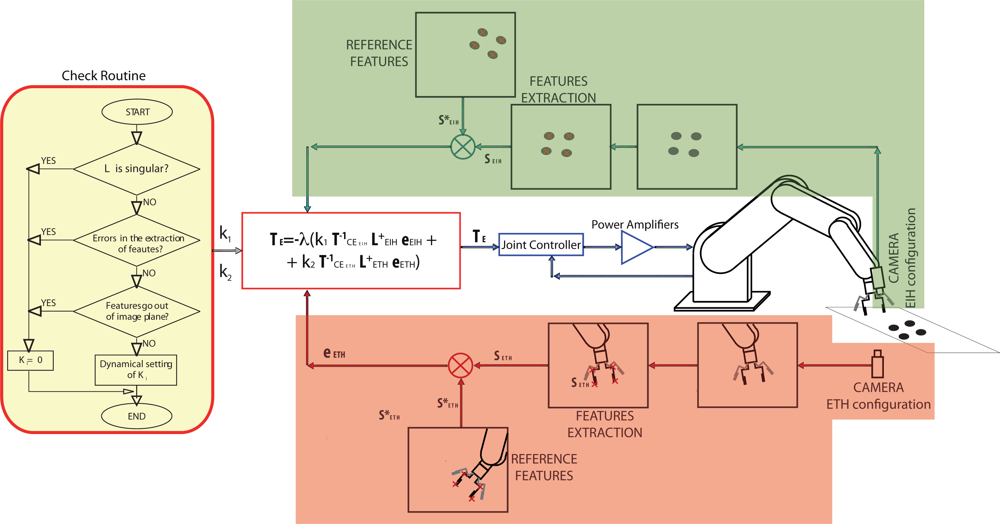
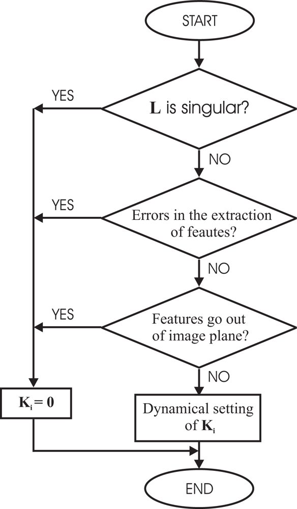
In Figure 2, a control scheme of the general architecture proposed by the authors can be seen. To implement it, a software function (Check routine) to give the corresponding values to k1 and k2 is used. This Check routine is shown in Figure 3 as flowchart.
2.2. Controller Implementation
It is obvious that the performance of the proposed system depends on the selection of the weights ki. Before giving the corresponding value to ki some rules have been taken into account to avoid typical problems of image-based visual servoing approaches like task singularities, features extraction errors, disappearance of features from the image plane, etc. To do this, a checking routine is executed and if one of the problems described before are produced, the corresponding value of ki will set to zero. In Figure 3, the flow chart of the checking routine can be seen. Obviously, the system fails if the problems happens in both configurations at the same time.
In Figure 3, the dynamical setting of ki box represents a function to give values to ki depending on some predefined criteria. In this paper, ki is computed in each sample time by the following function that depends on the relative image error:
The key idea of using this function is that the control contribution due to one of the cameras has more effect when its image features are far from their reference position. With this formulation of variable ki, the local minima problems are avoided since the change in the weights ki will bring the system away from it. So we can assure that e = 0 if and only if ei = 0 ∀ i.
3. Experimental Results
Experimental results has been carried out using a 7 axis redundant robot manipulator (only 6 of its 7 dof have been considered) based on Schunk modular motors. This robot has been designed and manufactured especially to perform visual servoing tasks and has a maximum allowable load of 10 Kg.
This robot (shown in Figure 1) is mounted using 7 PRL modules (two PRL-120, two PRL-100, two PRL-80 an one PRL-60) and links made of aeronautical aluminum (manufactured using a 5-axis milling machine). PRL modules are connected by a CAN-Open bus to a PCI CAN controller (ESD-electronics).
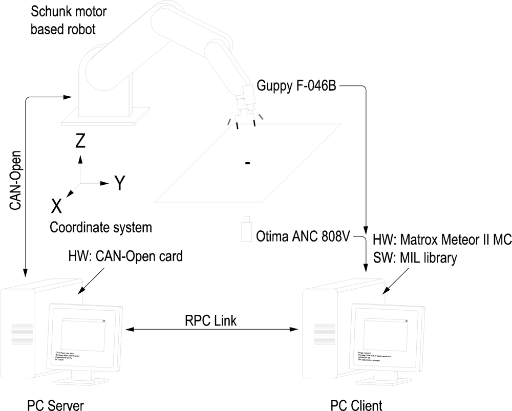
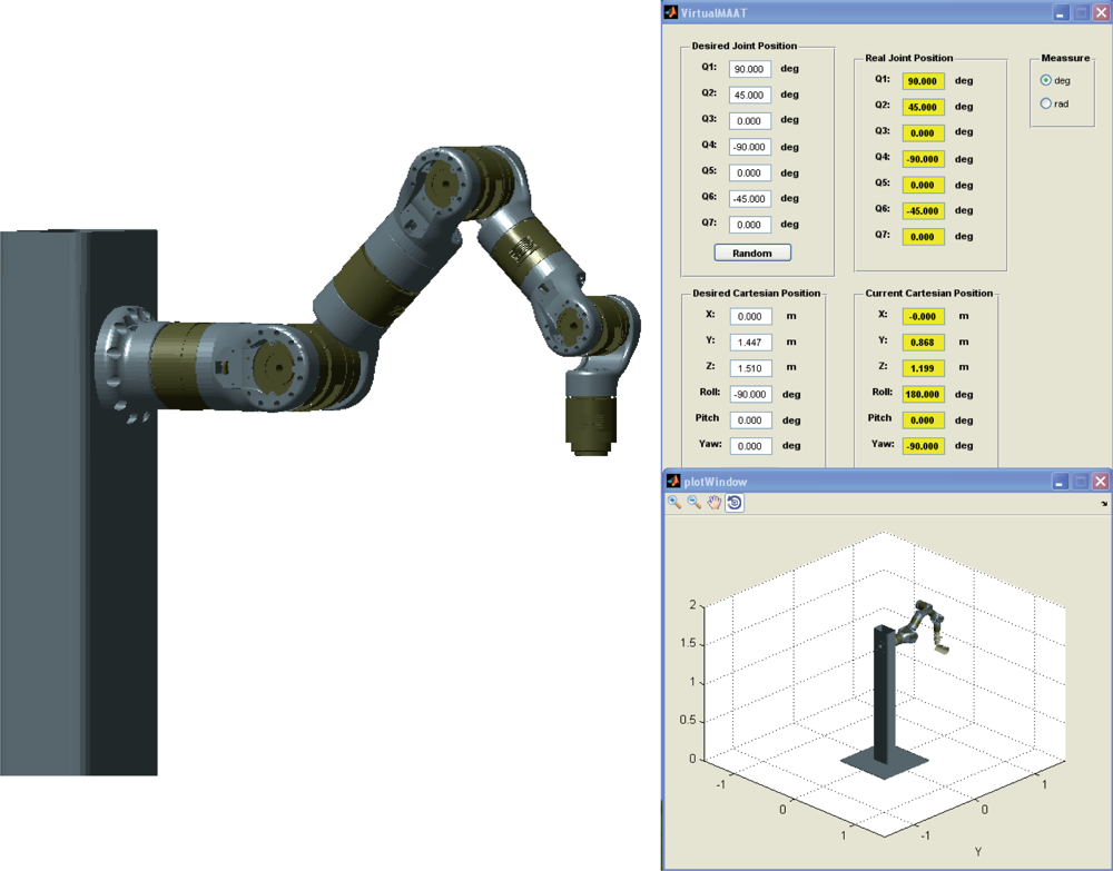
The experimental setup used in this work also includes a firewire camera (model Guppy F-046B, monochromatic, resolution of 780 × 582, 49 fps, Allied Vision Technologies) rigidly mounted in the robot end effector, a camera (manufactured by Otima, model ANC 808V Wired Type) observing the robot gripper, some experimental objects and a computer with a Matrox Meteor II MC vision board and other computer with a CAN-Open card to control the Schunk motor based robot. An RPC link between the robot controller and the computer with the vision board for synchronization tasks and data interchange has been implemented. The whole experimental setup can be seen in Figure 4. Moreover, a simulation environment has been implemented using Matlab and Simulink to test the control algorithms before to corroborate the simulation results in the experimental platform (shown in Figure 5). In the simulation environment, the robot dynamics and kinematics, camera models, errors in the extraction of image features, etc. have been considered in order to carry out simulations as close to real experimental environment as possible.
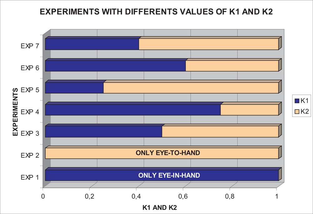
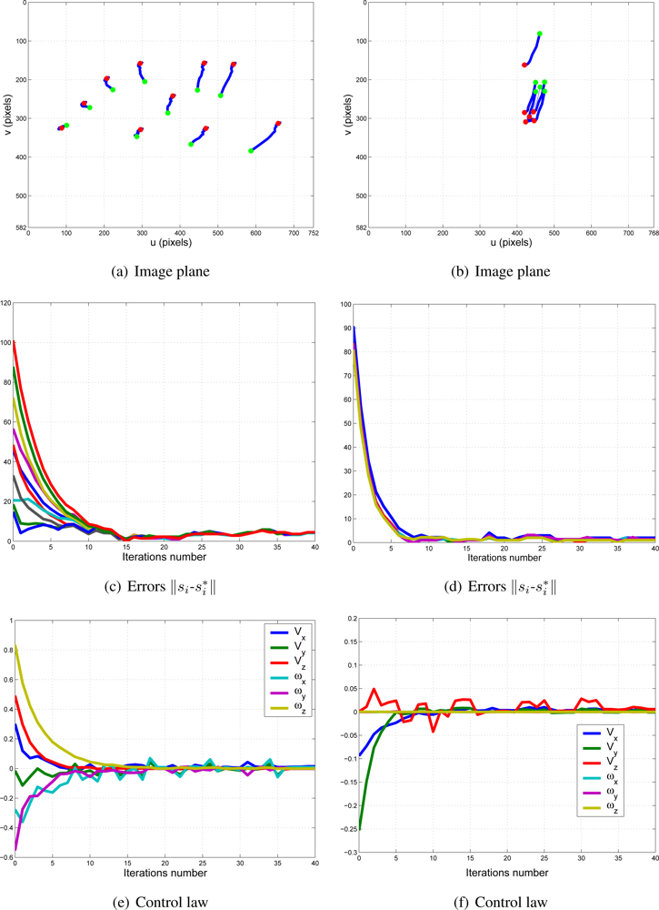
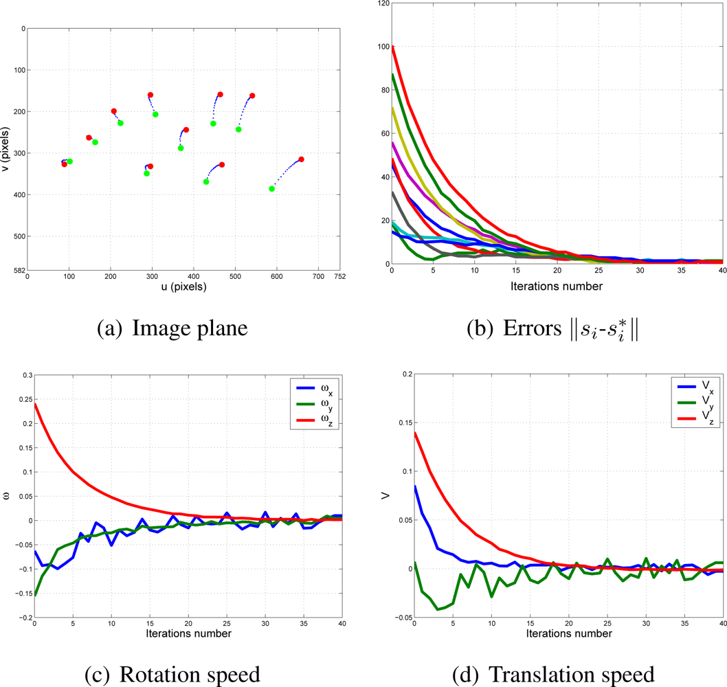
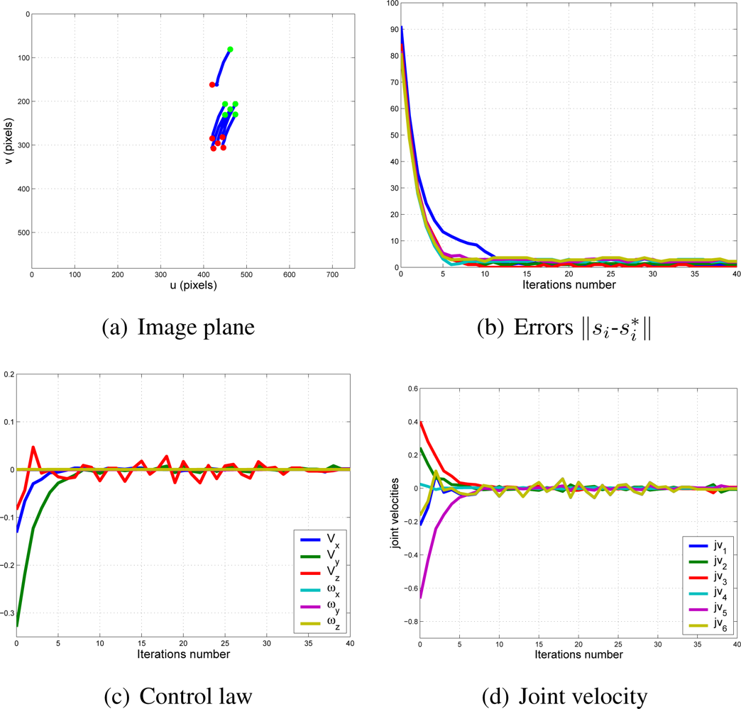
With this experimental setup, exhaustive number of experiments have been made with different constant weights during the control task (see Figure 6). In Figures 7 and 8, the results with k1 = 1, k2 = 0 (only the camera in eye-in-hand configuration is used) and k1 = 0, k2 = 1 (only the camera in eye-to-hand configuration is used) are presented. In these experiments, we could verify that each system is stable and the error tends to zero except the noise of feature extraction.
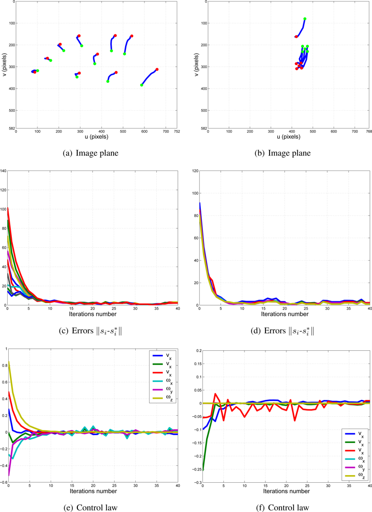
To adjust the value of k1 and k2, several experiments have been carried out. In Figures 9 and 10, the structure of the whole system is used since k1 ≠ 0 and k2 ≠ 0. In short, Figure 9 shows the obtained results with a constant weight of (k1 = 0.5 and k2 = 0.5). It means that both cameras contribute with 50% to the global control signals. Figure 10 shows the results with a constant weight of (k1 = 0.75 and k2 = 0.25). Taking a look carefully to the Figures 7–10, and the results of all the experiments carried out, we can realize that the system is stable and independent to the values of ki. These experiments corroborates the stability analysis presented at the end of Section 2. Assuring that each system is stable, the cooperative control system allows us to modify the magnitude of ki without risk of making the system unstable.
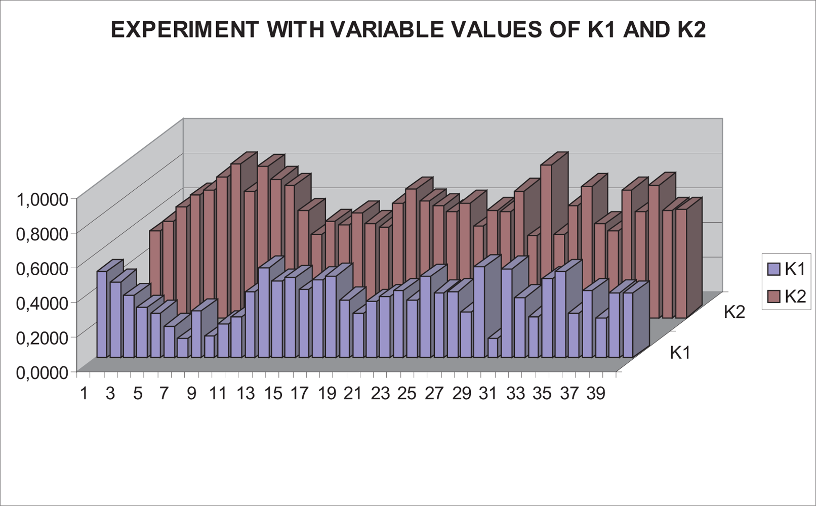
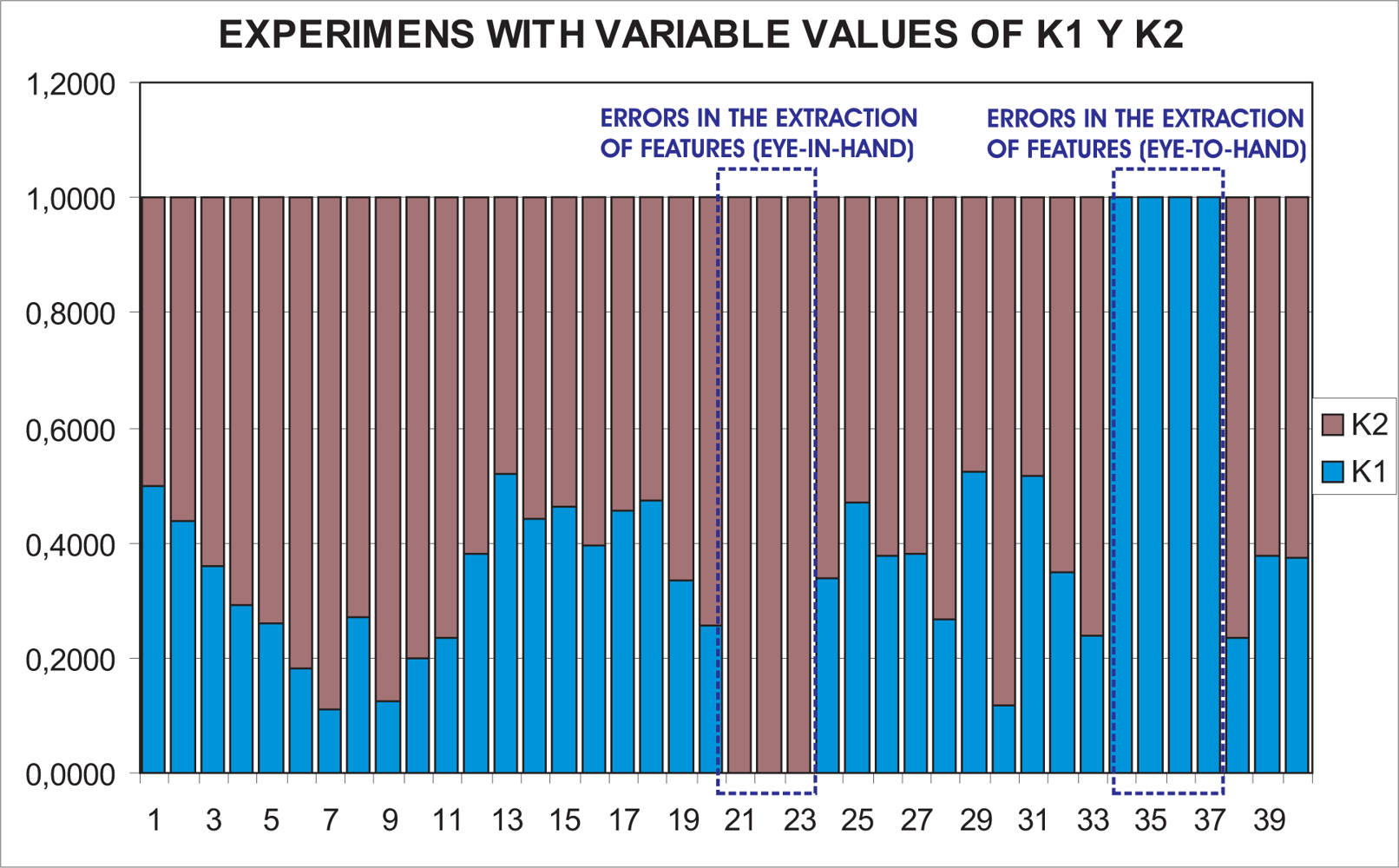
In this paper, the dynamical setting of ki (10) is used to carry out a huge number of experiments. In Figure 11, the values of k1 and k2 during the control task in one of the experiments can be seen. In Figure 12, the results of using a variable value of the weights are shown. Observing them, we can realize that the system is stable and the error tends to zero except the noise of feature extraction.
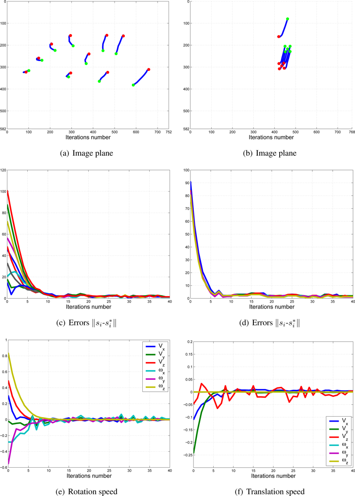
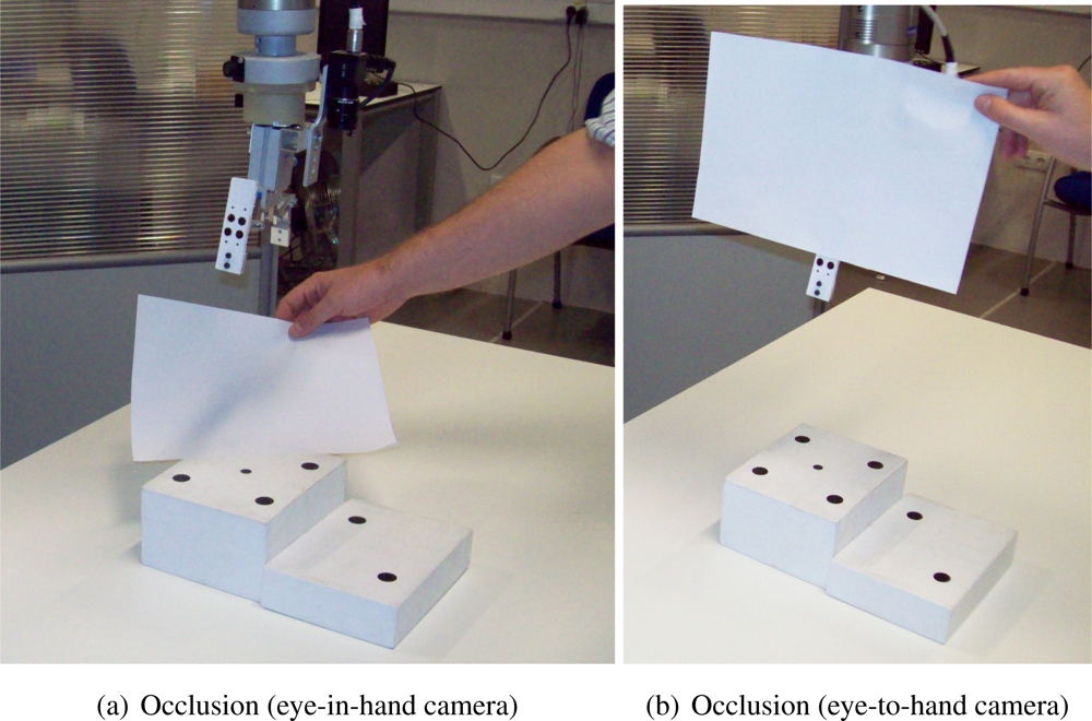
To show the performance of the proposed system with typical problems of image-based visual servoing approaches like task singularities, features extraction errors, disappearance of features from the image plane, many experiments have been carried out. The results of a simple experiment where features extraction errors are produced deliberately are shown in Figure 13. Observing Figures 13 and 14, we can see that:
Iterations 20–22: an error in the extraction of features (eye-in-hand configuration) is produced deliberately (Figure 14(a)). This error is detected by the checking routine (Section 2.2) and k1 is set to zero.
Iterations 33–36: an error in the extraction of features (eye-to-hand configuration) is produced deliberately (Figure 14(b)). This error is detected by the checking routine (Section 2.2) and k2 is set to zero.
In spite of these forced errors, the system is stable and the robot reaches its reference position accurately.
4. Conclusions
The redundant and cooperative visual servoing system proposed in this paper has been designed to make more robust the classical imaged based visual servoing systems. In all experimental results, the positioning accuracy of the architecture presented in this paper is better than the classical one and also problems like local minima, task singularities and features extraction errors are avoided. Moreover, the proposed architecture allows also to use several kinds of sensors like cameras, force sensors, etc. without excessive difficulty.
As future work, new functions to give values of ki are been analyzed to obtain an online method of parameter adjustment.
Acknowledgments
This work has been partly supported by the European Commission (FP7-ECHORD) and by Ministerio de Ciencia e Innovacion through the research project entitled “Simulador quirurgico e interfaz persona-maquina para la asistencia en tecnicas SILS/NOTES” (DPI2010-21126-C03-02).
References
- Chaumette, F.; Hutchinson, S. Visual servo control. Part I: Basic approaches. IEEE Robot. Automat. Mag 2006, 13, 82–90. [Google Scholar]
- Chaumette, F.; Hutchinson, S. Visual servo control. Part II: Advanced approaches. IEEE Robot. Automat. Mag 2007, 14, 109–118. [Google Scholar]
- Hutchinson, S.A.; Hager, G.D.; Corke, P.I. A tutorial on visual servo control. IEEE Trans. Robot. Automat 1996, 12, 651–670. [Google Scholar]
- Mezouar, Y.; Chaumette, F. Path planning for robust image-based control. IEEE Trans. Robot. Automat 2002, 534–549. [Google Scholar]
- Park, J.S.; Chung, M.J. Path planning with uncalibrated stereo rig for image-based visual servoing under large pose discrepancy. IEEE Trans. Robot. Automat 2003, 19, 250–258. [Google Scholar]
- Mezouar, Y.; Chaumette, F. Optimal camera trajectory with image-based control. IEEE Trans. Robot. Automat 2002, 22, 781–804. [Google Scholar]
- Morel, G.; Zanne, P.; Plestan, F. Robust visual servoing: Bounding the task function tracking errors. IEEE Trans. Control Syst. Tech 2005, 13, 998–1009. [Google Scholar]
- Chesi, G. Visual servoing path-planning via homogeneous forms and LMI optimizations. IEEE Trans. Robot. Autom 2009, 25, 281–291. [Google Scholar]
- Kazemi, M.; Gupta, K.; Mehrandezh, M. Global path planning for robust visual servoing in complex environments. Proceedings of ICRA 2009: IEEE International Conference on Robotics and Automation, Kobe, Japan, 12–17 May 2009; pp. 326–332.
- Chesi, G.; Shen, T. Conferring robustness to path-planning for image-based control. IEEE Trans. Control Syst. Tech 2011. [Google Scholar] [CrossRef]
- Mezouar, Y.; Chaumette, F. Path planning for robust image-based control. IEEE Trans. Robot. Autom 2002, 18, 534–549. [Google Scholar]
- Benhimane, S.; Malis, E. Vision-based control with respect to planar and non-planar objects using a zooming camera. Proceedings of ICRA 2003: IEEE International Conference on Advanced Robotics, Coimbra, Portugal, 30 June–3 July 2003.
- Garcia-Aracil, N.; Malis, E.; Aracil, R.; Perez-Vidal, C. Continuous visual servoing despite the changes of visibility in image features. IEEE Trans. Robot 2005, 21, 1214–1220. [Google Scholar]
- Perez-Vidal, C.; Gracia, L.; Garcia-Aracil, N.; Cervera, E. Visual control of robots with delayed images. Adv. Robot 2009, 23, 725–745. [Google Scholar]
- Marchand, E.; Comport, A.; Chaumette, F. Improvements in robust 2D visual servoing. Proceedings of ICRA 2004: IEEE International Conference on Robotics and Automation, New Orleans, LA, USA, 26 April–1 May 2004; pp. 745–750.
- Kragic, D.; Christensen, H. Cue integration for visual servoing. IEEE Trans. Robot 2001, 17, 19–26. [Google Scholar]
- Kosmopoulos, D.I. Robust Jacobian matrix estimation for image-based visual servoing. Robot. Comput. Integr. Manufact 2011, 27, 82–87. [Google Scholar]
- Malis, E.; Mezouar, Y.; Rives, P. Cue integration for visual servoing. IEEE Trans. Robot 2010, 26, 112–120. [Google Scholar]
- Aracil, R.; Garcia-Aracil, N.; Perez, C.; Paya, L.; Sabater, J.M.; Azorin, J.M.; Jimenez, L.M. Robust image-based visual servoing system using a redundant architecture. Proceedings of 6th IFAC World Congress, Prague, Czech Republic, 4–8 July 2005.
- Garcia-Aracil, N.; Perez, C.; Paya, L.; Neco, R.; Sabater, J.M.; Azorin, J.M. Avoiding visual servoing singularities using a cooperative control architecture. Proceedings of ICINCO(2) 2004: 1st International Conference on Informatics in Control, Automation and Robotics, Sedúbal, Portgual, 25–28 August 2004; pp. 162–168.
- Marchand, E.; Hager, G. Dynamic sensor planning in visual servoing. Proceedings of ICRA 1998: IEEE International Conference on Robotics and Automation, Leuven, Belgium, 16–20 May 1998; 3, pp. 1988–1993.
- Flandin, G.; Chaumette, F.; Marchand, E. Eye-in-hand/eye-to-hand cooperation for visual servoing. Proceedings of ICRA 2000: IEEE International Conference on Robotics and Automation, San Francisco, CA, USA, 24–28 April 2000; 3, pp. 2741–2746.
- Yoshihata, Y.; Watanabe, K.; Iwatani, Y.; Hashimoto, K. Multi-camera visual servoing of a micro helicopter under occlusions. Proceedings of IROS’07: IEEE/RSJ International Conference on Intelligent Robots and Systems, San Diego, CA, USA, 29 October–2 November 2007; pp. 2615–2620.
- Samson, C.; Le Borgne, M.; Espiau, B. Robot Control: The Task Function Approach, 1st ed.; Oxford Engineering Science Series; Clarendon Press: Oxford, UK, 1991; Volume 22. [Google Scholar]
- DeMenthon, D.; Davis, L.S. Model-based object pose in 25 lines of code. Proceedings of European Conference on Computer Vision, Santa Margherita Ligure, Italy, 19–22 May 1992; pp. 335–343.


© 2011 by the authors; licensee MDPI, Basel, Switzerland. This article is an open access article distributed under the terms and conditions of the Creative Commons Attribution license (http://creativecommons.org/licenses/by/3.0/).
Share and Cite
Garcia-Aracil, N.; Perez-Vidal, C.; Sabater, J.M.; Morales, R.; Badesa, F.J. Robust and Cooperative Image-Based Visual Servoing System Using a Redundant Architecture. Sensors 2011, 11, 11885-11900. https://doi.org/10.3390/s111211885
Garcia-Aracil N, Perez-Vidal C, Sabater JM, Morales R, Badesa FJ. Robust and Cooperative Image-Based Visual Servoing System Using a Redundant Architecture. Sensors. 2011; 11(12):11885-11900. https://doi.org/10.3390/s111211885
Chicago/Turabian StyleGarcia-Aracil, Nicolas, Carlos Perez-Vidal, Jose Maria Sabater, Ricardo Morales, and Francisco J. Badesa. 2011. "Robust and Cooperative Image-Based Visual Servoing System Using a Redundant Architecture" Sensors 11, no. 12: 11885-11900. https://doi.org/10.3390/s111211885