A Simple Fiber Bragg Grating-Based Sensor Network Architecture with Self-Protecting and Monitoring Functions

Abstract
: A novel fiber Bragg grating (FBG)-based passive sensor architecture, which can be used to protect the fiber cut and monitor the multiple sensors simultaneously, is proposed and experimentally demonstrated. Here, we employ a wavelength-tunable erbium-doped fiber (EDF) laser scheme with 25 km cavity length acting as the detecting light source in central office (CO). Each FBG sensor, serving as a feedback element, is used in proposed sensor architecture. By tuning the tunable bandpass filter (TBF) placing inside cavity to match the corresponding Bragg wavelength of FBG over the amplification bandwidth, we can retrieve the related wavelength lasing for the FBG sensing and monitoring simultaneously. Moreover, the survivability and capacity of the passive FBG sensor architecture can be also enhanced.1. Introduction
Using fiber Bragg gratings (FBG) to serve as the fiber-optic sensors are important studies in the field of optical sensing applications [1–3]. When strain or temperature variations are imposed on the FBG sensor, the Bragg wavelength will drift due to the index change of the FBG, and thus the detected wavelength will also shift. For distributed fiber sensors in intelligent sensing systems, the FBG-based sensor has been studied and identified as an important sensing element for sensing the change of temperature and strain [1–5]. Hence, a large-scale FBG sensor system could be built and achieved easily by a multiplexing method [6–8].
During the strain sensing, if the payload applied on the FBG is over its limitation, FBG breakage will occur. Furthermore, the fiber-fault of FBG-based sensing network also could affect the survivability and reliability. As a result, how to improve and enhance the reliability and survivability of sensor network becomes the essential issue for further study. To ensure the survivability of an FBG sensor system against fiber faults, a few self-protection schemes have been reported [9,10]. However, these methods required optical switches (OSWs) in each remote node (RN) to re-route the sensing path for detecting and protecting the fiber fault. It was hard to control and judge the direction of OSWs in each RN and also increased the complexity and cost of FBG-sensor networks. In addition, even though these FBG sensor systems were passive sensing networks in multi-ring schemes in the past studies [1,2], these ring sensor architectures required many numbers of RNs, consisting of optical coupler (OCP), to produce multi-ring configurations and result in the huge fiber connect points to reduce the power budget after run trip transmission.
In this study, a self-protected passive FBG sensor network, which enhances the reliability and survivability in long-reach fiber distance, is proposed and experimentally investigated. The sensing mechanism is based on a 25 km cavity length erbium-doped fiber (EDF) ring laser for detecting the multiple FBG sensors in the network. And we only use an optical coupler (OCP) on RN to produce the multi-ring configuration. The advantage of the proposed fiber laser scheme for detecting and monitoring the FBG sensors in the long distance self-protected scheme can facilitate highly reliable and survivable operation. Besides, the long distance sensing system can be integrated in fiber access network to reduce the cost of sensor infrastructure in the future.
2. Experiment and Discussion
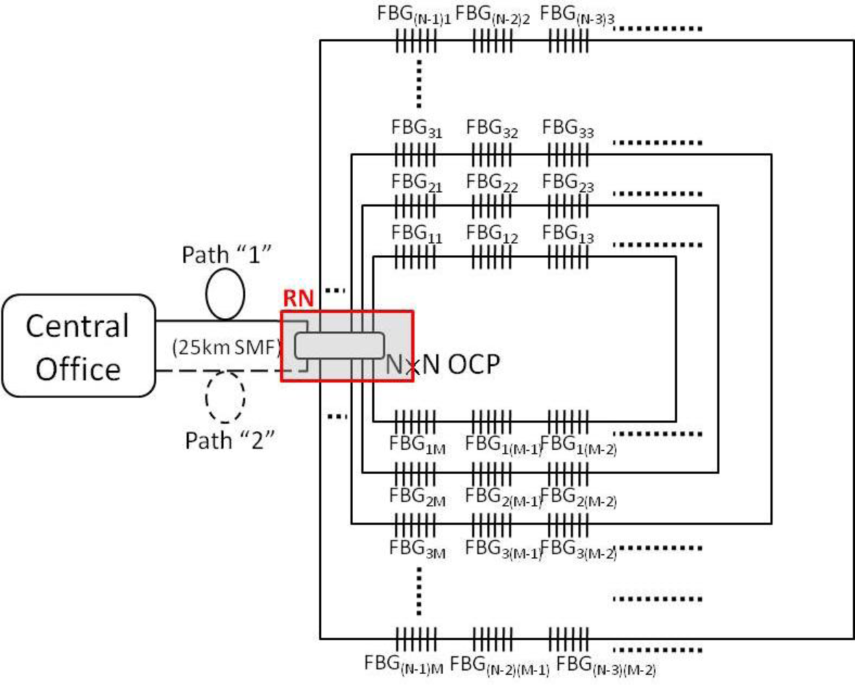
The proposed LR self-healing FBG-based sensor system consisted of a central office (CO) and multiple sensing networks, as shown in Figure 1. Here, two 25 km long single-mode fibers (SMFs) were used to connect to the CO and a N × N optical coupler (OCP), which was located at remote node (RN). The upper (path “1”) and lower SMFs (path “2”) were used to serve as the feeder fibers for sensing signal transmission. The N × N OCP could produce N – 1 fiber ring architectures and each ring scheme could use M FBGs for system sensing. A wavelength-tunable laser (WTL) source was used to detect and monitor the FBG sensors in the CO. For the initial deployment of the sensing network, the power budget (i.e., the power of the laser source and the split-ratio of the sensing network) should be carefully considered. If the power budget is not enough due to high split ratio, fiber amplifiers between CO and RN can be used to solve this issue. Besides, according to current passive access network standards [11], this proposed 25 km long sensor system can be also integrated in the fiber access system to enhance the use of capacity fiber and reduce the cost of sensor infrastructure.
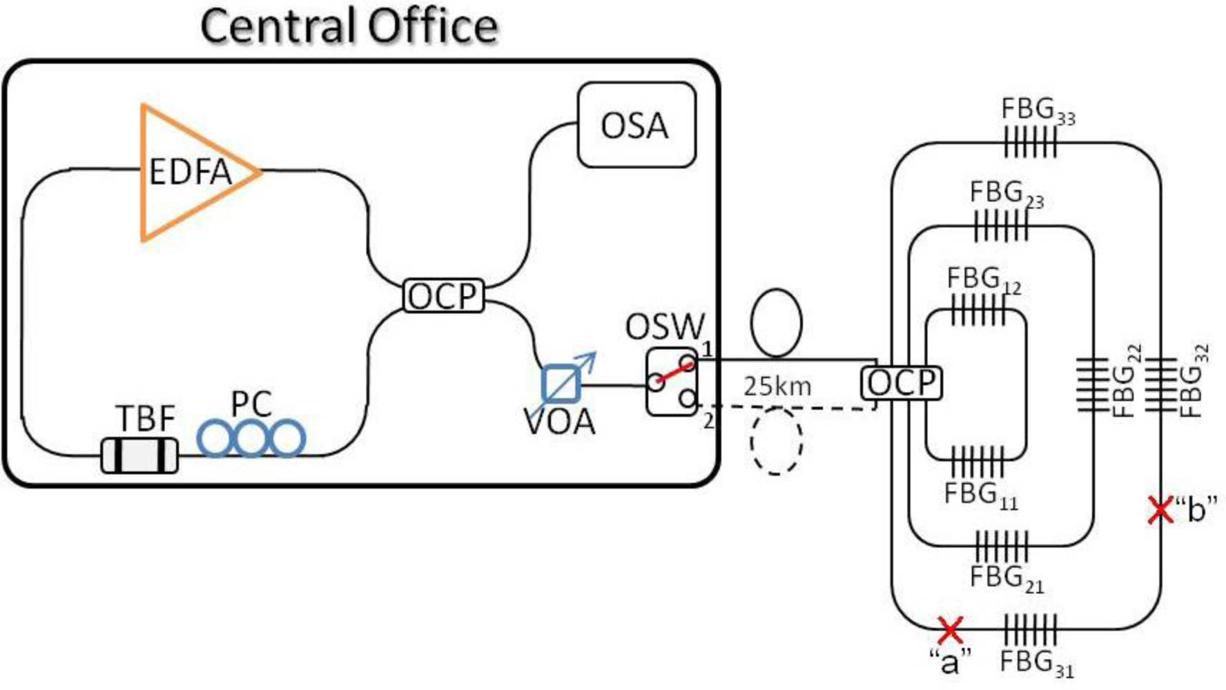
To realize and perform the proposed FBG-based sensor network, the experimental setup was based on a simplified version as illustrated in Figure 2. The CO was constructed by a WTL, a 1 × 2 OSW and an optical spectrum analyzer (OSA). In this measurement, the WTL was consisted of an erbium-doped fiber amplifier (EDFA), a tunable bandpass filter (TBF), a 4 × 4 OCP, a polarization controller (PC), a variable optical attenuator (VOA). The 980 nm pumping laser of EDFA operated at 215 mA and the saturated output power of the EDFA was around 16 dBm at 1,530 nm. The tuning range, insertion loss and 3 dB bandwidth of TBF used was 36 nm (1,526 to 1,562 nm), <0.7 dB and 0.3 nm, respectively. The PC and VOA were used to control and adjust the polarization status and maintain the maximum output power. Thereby, the 4 × 4 OCP would introduce three ring sensing networks. And the two feeder fibers were 25 km long. In the experiment, the sensor network has eight FBGs, which could be used for the strain and temperature sensing applications. Moreover, the Bragg wavelengths of these FBGs, which have different reflectivity, were 1,527.6 (λ11), 1,528.9 (λ12), 1,532.9 (λ21), 1,536.7 (λ22), 1,538.4 (λ23), 1,541.7 (λ31), 1,546.0 (λ32) and 1,556.0 nm (λ33), respectively.
The proposed WTL scheme in CO contained the C-band erbium-doped gain operation. And the passband of the TBF, using the inside gain cavity, was scanned to match the corresponding Bragg wavelength of FBG. Each FBG element served as the reflected sensor head and was connected as the part of cavity via a 25 km long fiber. Due to the inclusion of the TBF within the cavity loop, the lasing wavelength would be generated only when the filter passband was aligned in accordance with one of the FBG elements. In normal operation, when the TBF was set at one of the Bragg wavelength of the FBG, a long cavity fiber ring laser will be formed, and a lasing wavelength will be detected at the OSA located in the CO, with a 0.05 nm resolution.
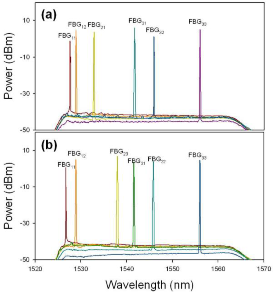
Initially, the OSW of CO was located on position “1” to connect to the sensor network via the upper feeder fiber (path “1”) for detecting and monitoring the eight FBG sensors used, as illustrated in Figure 2. Here, Figure 3(a) shows the reflected wavelengths of the proposed FBG-based sensor network from 1,527.6 to 1,556.0 nm (λ11 to λ33) via upper fiber. Here, we can observe eight lasing wavelengths in Figure 3(a) using the proposed WTL scheme during the TBF scanning. Of course, we could also connect the FBG sensor network for via the lower feeder fiber (path “2”), when the 1 × 2 OSW was switched to position “2”, as shown in Figure 2. Thus, Figure 3(b) presents the retrieved output wavelengths of the eight FBG sensors system via the lower feeder fiber. As shown in Figure 3(a) and Figure 3(b), no matter from which fibers to transmit the detecting signal to monitor FBG sensors, the measured reflective wavelengths are the same. However, the obtained wavelength λ11 of Figure 3(b) is slightly drifted due to the different forward and backward reflected spectrum of FBG11. As a result, we can switch the direction of OSW for connecting the upper or lower feeder fibers to monitor the status of FBG sensors and each ring fiber simultaneously.
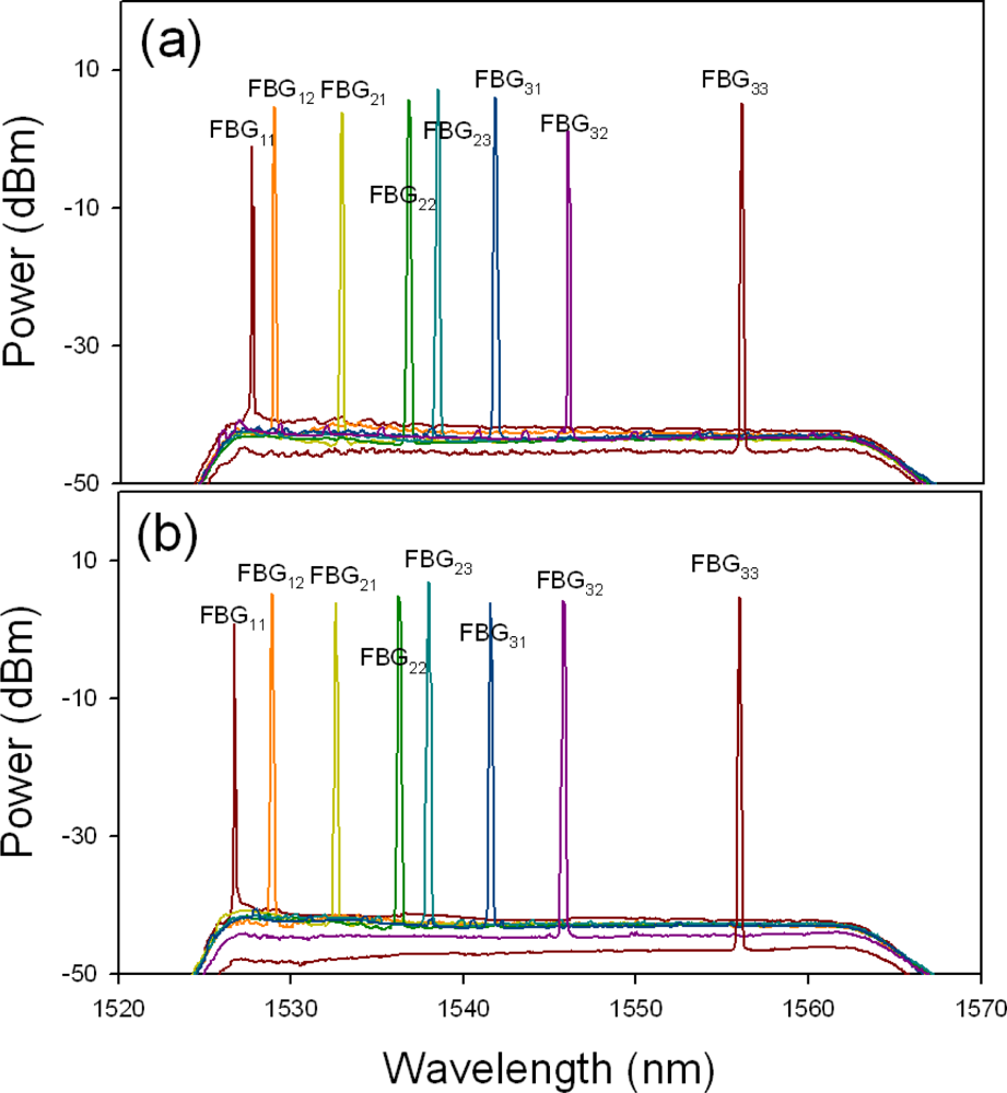
In the first scenario, the fiber fault may happen inside the fiber ring network. Hence, if a fiber cut occurs at point “b”, as seen in Figure 2, the lasing wavelengths of λ32 and λ33 can be not measured via the upper feeder path, as shown in Figure 4(a). At this moment, the OSW will switch to position “2” to connect the lower feeder fiber for rescanning the FBG sensors. Thus, only the wavelength λ31 cannot be retrieved by the proposed WTL scheme, as illustrated in Figure 4(b). According to the measured results of Figure 4(a) and Figure 4(b), then we can locate and ensure the cut position among FBG31 and FBG32. Besides, if two fiber cuts occur at point “a” and “b” simultaneously in the sensor network, the lasing wavelengths of λ31, λ32 and λ33 via the paths “1” and λ31 via the path “2” cannot be measured by OSA, respectively. Hence, we can ensure the faults are among points “a” and “b”. Furthermore, when the external strain is applied on FBG31 before breaking, wavelength shifts can be observed, as illustrated in Figure 5. Here, the maximum strain shift of FBG31 is nearly 2.2 nm. When the temperature of FBG increases gradually, the reflected wavelength of the FBG will shift. In the proposed FBG sensing network, certain sub-ring systems could be used for the temperature sensing. Besides, some FBG sensors are used for both temperature-sensing as well as fiber-cut location detection. In the measurement, the maximum wavelength shift of FBG31 is ∼2.2 nm when the temperature of FBG31 change is around 68 °C. While the strain exceeds the limitation of FBG31, the FBG sensor will be broken. In such situation, if a fault occurs on FBG31, the measured lasing wavelengths in CO are the same comparing with the results of Figure 4. However, we can first observe the wavelength drift before FBG breakage. As a result, we can clearly know the differences of fiber-fault and FBG-fault in the proposed passive FBG sensor network.
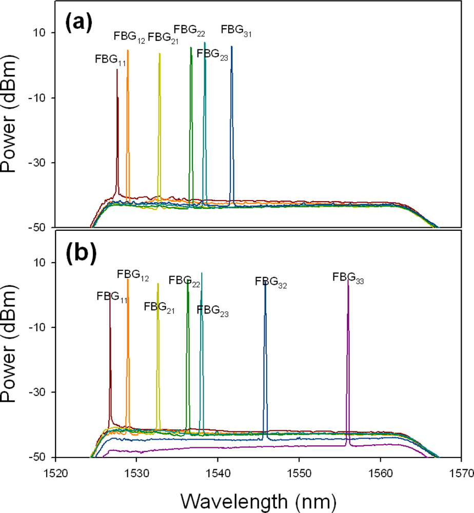
In addition, it is necessary to ensure that each FBG sensor was in good condition in a fiber sensor system. Thus, when the strain or temperature change was applied on each FBG sensor due to the environmental or artificial effects, the sensor will cause the Bragg wavelength shift. For the second scenario, while the payload of the FBG exceeds the limitation, the FBG would be broken. Here, the proposed ring sensor architecture also could find the position of the broken FBG. For example, if the FBG22 was broken in the proposed sensor network via the fiber path “1”, the lasing wavelengths of λ22 and λ23 would not be detected, as shown in Figure 6(a). Hence, to detect the disappeared FBG sensors, the CO would control the OSW to reconnect to the lower feeder fiber (path “2”) for sensing FBG. Thus, the measured output spectrum lacks the λ21 and λ22, as shown in Figure 6(b). Comparing the two output spectra of Figures 6(a) and 6(b), we can easily locate the fault is on FBG22. Moreover, for example, when the measured lasing spectra of the λ11, λ12, λ21, λ22 and λ23 via the fiber path “1”, and λ11 and λ21 via the fiber path “2” respectively, are not detected by the proposed sensor system, we can assure that two sensors of FBG11 and FBG21 are broken this time.
We can follow the above measurement methods to ensure when the sensing path is via the feeder fiber paths “1” and “2”. Initially, we can observe entire reflected wavelengths of FBG sensors via feeder path “1” when this sensing network is without FBG fault or fiber fault. When a fault is produced on FBGxy, first we can observe that the reflective-wavelength of measured FBGxy should be shift and then broken. Based on the measured result, we can realize the fault which is on FBG not on fiber. Besides, when the occurrence of fiber fault is produced, all the observed reflective-wavelengths are not change at this time. As a result, the proposed FBG sensor system not only can find out the fiber fault, but also detect and monitor the FBG sensors.
3. Conclusions
In summary, we have proposed and experimentally investigated a simple self-restored FBG based sensor ring system for long distance sensing. Besides, there is no active component in the FBG sensor architecture for cost reduction. The sensing mechanism is based on a 25 km cavity length erbium-doped fiber (EDF) ring laser for detecting the multiple FBG sensors in the network. In this experiment, three scenarios of fault detections were experimentally studied, showing that the sensing network survivability, reliability and capacity for the multiple sensors can be enhanced. In the future, this proposed sensing network can be integrated into a fiber access network for advanced applications.
References
- Yeh, C.H.; Chow, C.W.; Wang, C.H.; Shih, F.Y.; Wu, Y.F.; Chi, S. A simple self-restored fiber Bragg grating (FBG)-based passive sensing network. Meas. Sci. Technol 2009, 20, 043001. [Google Scholar]
- Peng, P.C.; Tseng, H.Y.; Chi, S. Fiber-Ring Laser-Based Fiber Grating Sensor System Using Self-Healing Ring Architecture. Microwave Opt. Technol. Lett 2002, 35, 441–444. [Google Scholar]
- Zhang, B.; Kahrizi, M. High-temperature resistance fiber Bragg grating temperature sensor fabrication. IEEE Sens. J 2007, 7, 86–591. [Google Scholar]
- Zhao, Y.; Zhao, H.W.; Zhang, X.Y.; Meng, Q.Y.; Yuan, B. A Novel double-arched-beam-based fiber Bragg grating sensor for displacement measurement. IEEE Photonic. Technol. Lett 2008, 20, 1296–1298. [Google Scholar]
- Jin, L.; Zhang, W.; Zhang, H.; Liu, B.; Zhao, J.; Tu, Q.; Kai, G.; Dong, X. An embedded FBG sensor for simultaneous measurement of stress and temperature. IEEE Photonic. Technol. Lett 2006, 18, 154–156. [Google Scholar]
- Yeh, C.H.; Lin, M.C.; Lee, C.C.; Chi, S. Fiber Bragg grating-based multiplexed sensing system employing fiber laser scheme with semiconductor optical amplifier. Japan. J. Appl. Phys. Part 1 2005, 44, 6590–6592. [Google Scholar]
- Chung, W.H.; Tam, H.Y.; Wai, P.K.A.; Khandelwal, A. Time- and wavelength-division multiplexing of FBG sensors using a semiconductor optical amplifier in ring cavity configuration. IEEE Photonic. Technol. Lett 2005, 17, 2709–2711. [Google Scholar]
- Yeh, C.H.; Chi, S. Fiber-fault monitoring technique for passive optical networks based on fiber Bragg gratings and semiconductor optical amplifier. Opt. Commun 2006, 257, 306–310. [Google Scholar]
- Peng, P.C.; Lin, W.P.; Chi, S. A self-healing architecture for fiber Bragg grating sensor network. Proceedings of the 3rd IEEE International Conference on Sensors, Vienna, Austria, 24–27 October 2004; 1, pp. 60–63.
- Wu, C.Y.; Feng, K.M.; Peng, P.C.; Lin, C.Y. Three-dimensional mesh-based multipoint sensing system with self-healing functionality. IEEE Photonic. Technol. Lett 2010, 22, 565–567. [Google Scholar]
- 2003.


© 2011 by the authors; licensee MDPI, Basel, Switzerland. This article is an open access article distributed under the terms and conditions of the Creative Commons Attribution license (http://creativecommons.org/licenses/by/3.0/).
Share and Cite
Yeh, C.-H.; Chow, C.-W.; Wu, P.-C.; Tseng, F.-G. A Simple Fiber Bragg Grating-Based Sensor Network Architecture with Self-Protecting and Monitoring Functions. Sensors 2011, 11, 1375-1382. https://doi.org/10.3390/s110201375
Yeh C-H, Chow C-W, Wu P-C, Tseng F-G. A Simple Fiber Bragg Grating-Based Sensor Network Architecture with Self-Protecting and Monitoring Functions. Sensors. 2011; 11(2):1375-1382. https://doi.org/10.3390/s110201375
Chicago/Turabian StyleYeh, Chien-Hung, Chi-Wai Chow, Ping-Chun Wu, and Fan-Gang Tseng. 2011. "A Simple Fiber Bragg Grating-Based Sensor Network Architecture with Self-Protecting and Monitoring Functions" Sensors 11, no. 2: 1375-1382. https://doi.org/10.3390/s110201375