Ultra-Abrupt Tapered Fiber Mach-Zehnder Interferometer Sensors

Abstract
: A fiber inline Mach-Zehnder interferometer (MZI) consisting of ultra-abrupt fiber tapers was fabricated through a new fusion-splicing method. By fusion-splicing, the taper diameter-length ratio is around 1:1, which is much greater than those (1:10) made by stretching. The proposed fabrication method is very low cost, 1/20–1/50 of those of LPFG pair MZI sensors. The fabricated MZIs are applied to measure refractive index, temperature and rotation angle changes. The temperature sensitivity of the MZI at a length of 30 mm is 0.061 nm/°C from 30–350 °C. The proposed MZI is also used to measure rotation angles ranging from 0° to 0.55°; the sensitivity is 54.98 nm/°. The refractive index sensitivity is improved by 3–5 fold by fabricating an inline micro–trench on the fiber cladding using a femtosecond laser. Acetone vapor of 50 ppm in N2 is tested by the MZI sensor coated with MFI–type zeolite thin film. The proposed MZI sensors are capable of in situ detection in many areas of interest such as environmental management, industrial process control, and public health.
1. Introduction
Optical fiber sensors have attracted tremendous research interest in recent years [1–4]. Among many promising photonic devices, fiber-based Mach-Zehnder interferometers (MZI) stand out for their compactness, capability of responding to a wide variety of measurands, and relatively simple fabrication process. A number of fabrication techniques have been proposed to make fiber MZIs, including fiber tapering [5,6], core mismatch [7], imbedded micro air–cavity in fiber [8,9], pairing of LPFGs [10], laser heating induced microbending [11], and microstructure collapsing on a photonic crystal fiber [12].
High-order cladding modes are excited in fiber MZIs, which are guided by the cladding-ambient interface and directly exposed to the environment. The refractive index change of the environment can significantly change the effective propagation constant of the cladding modes. Thus, fiber MZIs can be used as a refractive index sensor by testing the phase shift of interference fringe. Fiber MZIs are also used to detect temperature, curvature, strain and stress [5,7,12]. It was discovered that the unique combination of optical and chemical properties of zeolites could be used to develop optical chemical sensors with high sensitivity [13]. Pure silica MFI-type zeolite thin film on long period fiber gratings was successfully synthesized for highly sensitive detection of organic vapors [14].
Recent developments in femtosecond laser technology have opened new possibilities for one-step fabrication (without additional assembly) of micro/nano-scale three-dimensional (3D) structures in various solid materials with greatly reduced collateral damage. Especially, new opportunities for laser micromachining of fiber optics devices are possible using ultrashort laser pulses. By using femtosecond lasers, various structures have been fabricated in fibers and used in the sensing field [15–18].
Among the various types of MZIs, fiber taper-based structures have the advantages of simplicity and high repeatability [5,6]. To obtain effective coupling between core and cladding modes, large taper angles are preferred [19]. Fiber tapers are usually made by stretching a fiber under high heat or electrical arc conditions, which limits the shortest length of the device. The tapered region has a typical length of ∼600 μm [6]. This study proposes an MZI consisting of two ultra-abrupt fiber tapers fabricated by a fusion splicer using ordinary single mode fibers. By fusion-splicing, the taper diameter-length ratio is 1:1, which is much greater than those (1:10) made by stretching reported in the previous works [5,6]. When it is used as a RI sensor, the sensitivity is comparable to LPFG pair MZI sensors [10] and the taper-based MZI sensors fabricated by stretching method [5,6]. However, the fabrication process is much simpler and has much higher robustness. The refractive index sensitivity is improved by 3–5 fold through imbedding an inline side-ablated micro-trench on the fiber cladding using a femtosecond laser. The MZI sensors are applied for direct measurement of acetone vapor of 50 ppm in N2 after coated with zeolite thin film. In addition, temperature and rotation angle tests are also conducted.
2. Device Principle
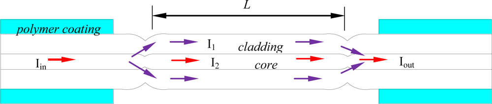
Figure 1 shows the schematic diagram of the MZI consisting of two ultra-abrupt fiber tapers. The input testing laser beam (Iin) is split into two portions in the first ultra-abrupt taper: one (I1) through the core and the other (I2) through the cladding. Part of the light (I1) in cladding modes is coupled back into the core at the second ultra-abrupt taper. Interference between the light traveling in the cladding and that traveling in the core is detected by measuring Iout.
The interference signal reaches minimum when the phase difference between cladding and core modes satisfies the following condition [7]:
3. Device Fabrication
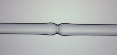
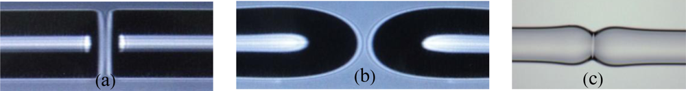
The fiber inline Mach-Zehnder interferometer is fabricated by the following steps using a conventional fusion splicer (model IFS-9, INNO INSTRUMENT, Inc., Korea): (a) the two normal cleaved ends are made ellipsoidal by a one time discharge (Figure 2(a,b) are the CCD images of the normal cleaved ends and ellipsoidal heads, respectively); (b) the two ellipsoidal heads are moved into contact in the center of the splicer electrodes, and will be fused together by another discharge; (c) the other ultra-abrupt fiber taper is formed through the same process separated by a distance L.
Figure 2(c) shows the microscope image of the ultra–abrupt fiber taper after the two ellipsoidal heads are fused together. To minimize the losses and achieve robust splices, the arc duration and current are set 60% (1,200 ms) and 50% of the default value, respectively. The fiber core and cladding are melted together at the ellipsoidal region, and the two ends are touching each other with deformation. Due to the fusion and deformation of the fiber core and cladding, part of the light spread into the cladding at the first ultra-abrupt taper and meet with the light transmitting in the core at the second ultra-abrupt taper. Both the length and diameter of the fabricated taper are only ∼100 μm, and the taper diameter-length ratio is around 1:1. Compared to the previously reported abrupt fiber tapers whose diameter-length ratios are around 1:10 [5,6], the taper fabricated by fusion-splicing is an ultra-abrupt one. It is more robust than MZIs consisting of stretched fiber tapers with the length of ∼600 μm and diameter of ∼60 μm [5,6].
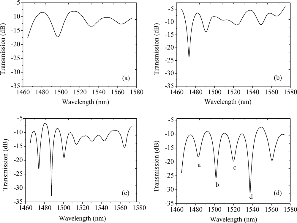
A detection system consisting of a tunable laser (Agilent 81980A) and an optical power meter (Agilent 8163B) is employed to measure the transmission spectra by wavelength sweeping. The tunable laser scans through its wavelength range (1,465–1,575 nm) at the rate of 5 pm per step. The transmission spectra of fiber in-line MZI with different lengths are shown in Figure 3. Clear interference fringes are obtained with the maximum attenuations of 9 dB, 18 dB, 25 dB and 22 dB for interferometer length of 20 mm, 30 mm, 36 mm and 40 mm, respectively. The background loss is around 8 dB.
4. Sensor Applications
4.1. Measurements of Refractive Index Change
The effective refractive index of the cladding mode changes with the variations of external refractive index, and it results in a shift of the maximum attenuation wavelength. The sensitivity can be expressed as [7]:
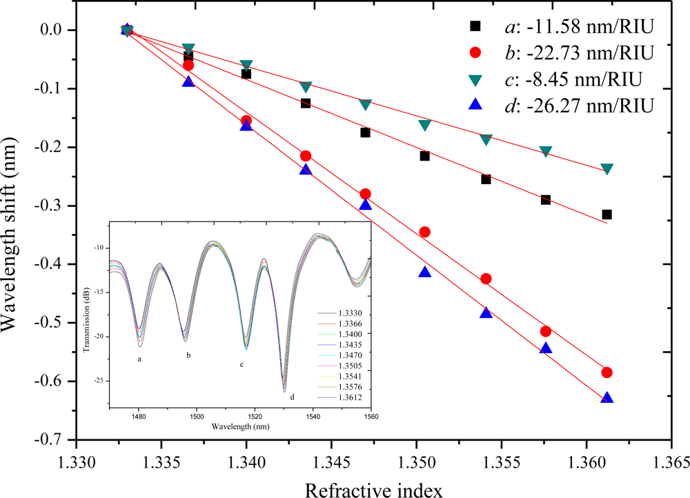
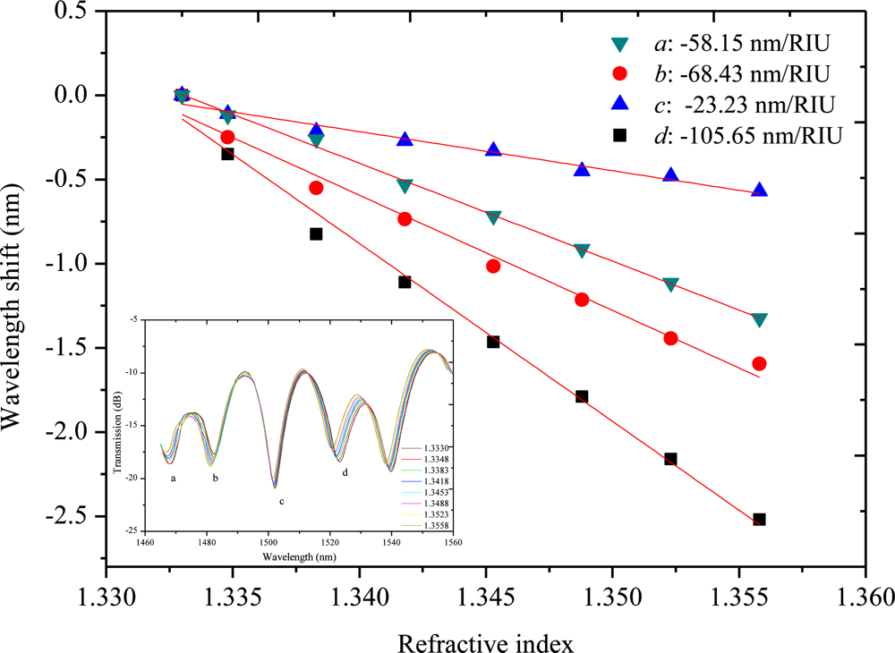
The MZI with a length of 40 mm is tested as a refractive index sensor. Salt solutions with various concentrations (0.0%, 1.96%, 3.85%, 5.66%, 7.41%, 9.09%, 10.71%, 12.28%, 13.79%, mass percent) are used in the experiments. The corresponding RIs are 1.3330, 1.3366, 1.3400, 1.3435, 1.3470, 1.3505, 1.3541, 1.3576, and 1.3612, respectively [20]. Four attenuation peaks are chosen as the record wavelengths, which are marked by a, b, c and d in Figure 3(d). It denotes the maximum attenuation wavelengths of 1,486.92, 1,501.55, 1,519.85 and 1,537.56 nm, respectively. Figure 4 shows the shift of the four maximum attenuation wavelengths with the respect to the external RI change. All the attenuation peaks shift to shorter wavelength region with the increase of external refractive index. The sensitivities are −11.58, −22.73, −8.45 and −26.27 nm/RIU, respectively. In the RI range of 1.333–1.3648, the sensitivity is similar to those of LPFG pair MZI sensors [10] and the tapered-fiber pair MZI sensors [5,6]. It also demonstrates that refractive index sensitivity varies with the maximum attenuation peaks. The main reason is that different cladding modes have different mode field areas, and the sensitivities are different for various cladding modes. As a recent work reported by Li et al. [21], higher order cladding modes have lager mode field areas and are more easily affected by the surrounding refractive index, hence, higher order cladding modes generally exhibit lower mode indices and higher sensitivities. The different sensitivity results showed in our study are in accordance with the peak shift discrepancy reported in [21].
4.2. Temperature Measurement
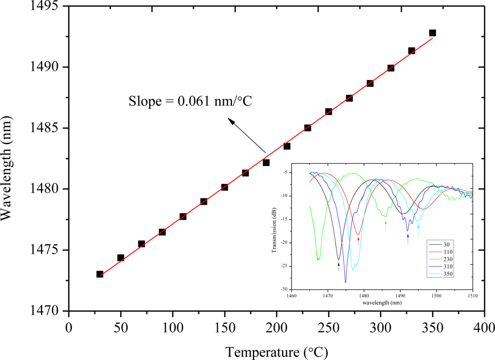
Due to the difference between the effective refractive index changes of cores and those of claddings in response to the temperature variations, the MZI can be used as a temperature sensor. In a muffle furnace, a 30 mm long MZI is used to test temperature sensitivity. The temperature changes every 5 min from 30 °C to 350 °C with a step of 20 °C. Figure 5 shows the attenuation maximum wavelength (around 1,473 nm) shift as a function of the temperature where the relation is roughly linear. A red shift occurs as the temperature increases, and the sensitivity is 0.061 nm/°C through a linear-fitting of the measured data, which is as good as those of grating-based temperature sensors [22]. The sensitivity of temperature is about 0.02 °C with the detection system of 1 pm resolution.
4.3. Angular Displacement Measurement
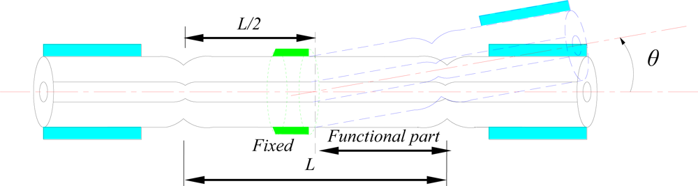
In this paper, the proposed MZI is used to measure angular displacement by fixing it on a micro-rotation stage. The corresponding structural diagram is shown in Figure 6.
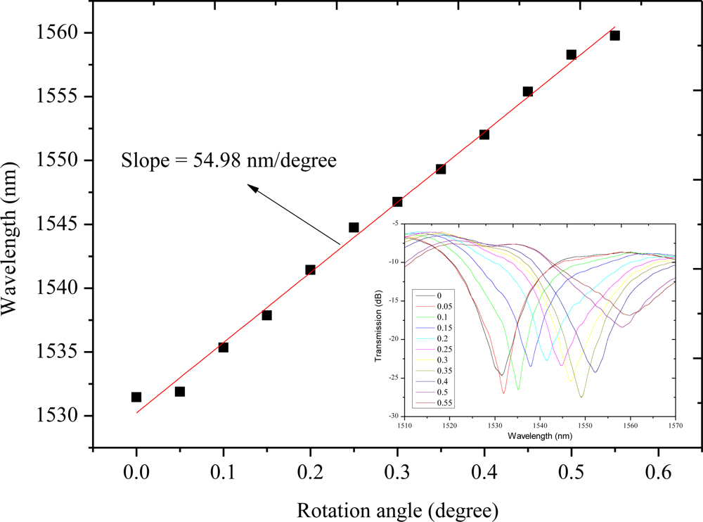
Because of the macro-bending, the coupling of the core mode to the cladding modes is changed by the variation of angle θ. By recording the wavelength shift in the transmission spectrum, we can test the angular displacement. An MZI with length of 25 mm is chosen to test the angular-displacement sensitivity in the angle range from 0° to 0.55° with an increment of 0.05° for a total of 11 steps. Figure 7 shows the attenuation maximum wavelength (around 1,530 nm) shift as a function of the angle θ. The sensitivity is 54.98 nm/° with good linearity. At a resolution of 1pm of the detecting system, the detection limit is 3.17 × 10⁻⁷ rad. Compared to other methods [23], the proposed MZI sensors are of many advantages including structure simpleness, reliability, compactness, robustness, low detection limit, and simple low-cost fabrication process.
4.4. RI Sensitivity Improved by the Femtosecond Laser
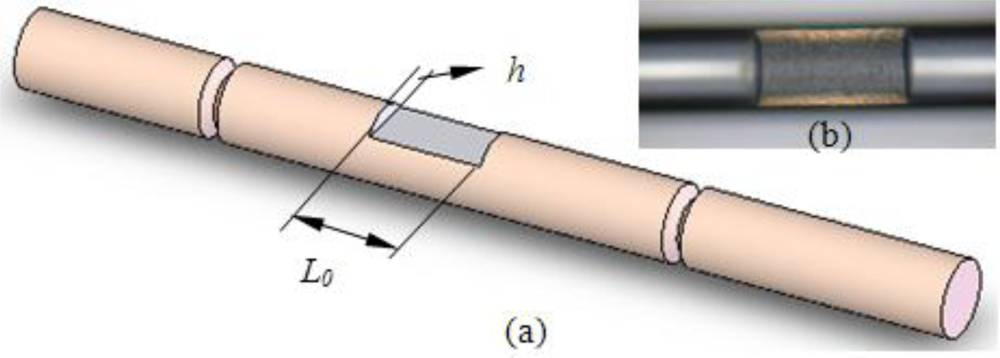
In order to improve the RI sensitivity of the proposed MZI sensor, an inline side-ablated micro-trench was fabricated to remove part of the fiber cladding using a femtosecond laser. The micro-trench lies in the center of the MZI, as shown in Figure 8(a). When part of the fiber cladding is removed, the optical power related to the evanescent wave of cladding modes significantly increases in the external medium. Thus, the enhancement of sensitivity is expected when the fiber cladding of the interaction area between the sensor and the medium is reduced.
A side-ablated micro-trench is fabricated in the aforementioned MZI (L = 40 mm) to improve the RI sensitivity. Figure 8(b) shows microscopic image of the fabricated micro-trench with an ablated depth (h) of 18 μm and a length (L0) of 200 μm, respectively. The width of 88 μm is obtained accordingly for the fiber is cylinder. The measured salt solutions are the same as in session 4.1. Salt solutions with various concentrations (0.0%, 0.99%, 2.91%, 4.76%, 6.54%, 8.26%, 9.91%, 11.50%, mass percent) are used in the experiments. The corresponding RIs are 1.3330, 1.3348, 1.3383, 1.3418, 1.3453, 1.3488, 1.3523 and 1.3558, respectively [20]. For the MZI imbedded by a micro-trench, the attenuation peaks marked by a, b, c and d in Figure 3(d) are changed to 1,483.4, 1,501.86, 1,520.72 and 1,538.06 nm, respectively. Figure 9 shows the shift of the four maximum attenuation wavelengths with respect to the external RI change. All the attenuation peaks shift to shorter wavelength region with the increase of external refractive index. The improved sensitivity becomes −58.15, −68.43, −23.23 and −105.65 nm/RIU, respectively. The sensitivity is improved by 3–5 fold for various interference modes. This value is comparable to LPFG sensors after specially designed for sensitivity enhancement [24].
4.5. Zeolite Coated MZI Sensor for Organic Vapors Tests
Zeolites are aluminosilicate materials with three dimensional crystalline porous skeletons, possessing unique chemical and optical properties which can be used to develop highly sensitive optical chemical sensors. The large surface-to-mass ratio of these pores could also efficiently adsorb (thus collect and concentrate) molecules from the ambient for highly sensitive detection. In this paper, MFI-type zeolite thin film is synthesized on the MZI for detection of acetone vapors with high sensitivity. The zeolite film is coated on the MZI cylindrical surface by in situ crystallization from an aluminum-free precursor solution using tetrapropylammonium ion as the structure directing agent. The details for zeolite coating are given in [14].
The sensor measure gas concentrations by monitoring the molecular adsorption-induced changes of the interference pattern position. The sensitivity is affected by many parameters such as the type of the zeolite, the film thickness, the measurands and the characteristics of the MZI. The length of the MZI is 36 mm, while the transmission spectrum is changed completely after being coated with zeolite film (as shown in Figure 10). We study the sensitivities of two maximum attenuation peaks (marked in Figure 10) in the transmission spectra. As the acetone vapor concentration increases, a blue shift is observed in the transmission spectra. The sensitivities of the 1st and 2nd attenuation peaks are −3.83 pm/ppm and −4.67 pm/ppm through linear fitting, respectively.
5. Conclusions
High-quality fiber inline MZIs are fabricated by a new fusion-splicing method using ordinary single mode fibers. By fusion-splicing, the taper diameter-length ratio is 1:1, which is much greater than those (1:10) achieved by stretching. The fabricated MZIs are applied to sense refractive index, temperature and rotation angle changes. The temperature sensitivity is 0.061 nm/°C in 30–350 °C. At a resolution of 1 pm of the detecting system, a detection limit is 3.17 × 10⁻⁷rad when the proposed MZI is used to measure angular displacements. The proposed fabrication method is very low cost, 1/20–1/50 that of LPFG pair MZI sensors. The RI sensitivity is improved by 3–5 fold after an inline side micro-trench is ablated by a femtosecond laser on the fiber cladding. In addition, the MZI sensor is used to measure acetone vapor of 50 ppm in N2 after being coated with zeolite thin film. The MZI sensors are of very high fabrication and sensing repeatability, thus offering many advantages including structure simpleness, reliability, compactness, robustness, high sensitivity, high flexibility and simple low-cost fabrication process. Moreover, such a robust and low-cost MZI sensor is capable of in situ detection in many areas such as environmental management, industrial process control, and public health.
Acknowledgments
This research is supported by the National Natural Science Foundation of China (NSFC) (Grants 90923039 and 51025521) and the 863 of Ministry of Science and Technology of China (Grant 2008AA03Z301).
References
- James, SW; Tatam, RP. Optical fiber long-period grating sensors: Characteristics and application. Meas. Sci. Technol 2003, 14, R49–R61. [Google Scholar]
- Lin, C-H; Jiang, L; Xiao, H; Chai, Y-H; Chen, SJ; Tsai, H-L. Fabry-perot interferometer embedded in a glass chip fabricated by femtosecond laser. Opt. Lett 2009, 34, 2408–2410. [Google Scholar]
- Guo, X; Tong, L. Supported microfiber loops for optical sensing. Opt. Express 2008, 16, 14429–14434. [Google Scholar]
- Fang, X; Liao, CR; Wang, DN. Femtosecond laser fabricated fiber Bragg grating in microfiber for refractive index sensing. Opt. Lett 2010, 35, 1007–1009. [Google Scholar]
- Lu, P; Men, L; Sooley, K; Chen, Q. Tapered fiber Mach-Zehnder interferometer for simultaneous measurement of refractive index and temperature. Appl Phys Lett 2009, 94. No. 131110. [Google Scholar]
- Tian, Z; Yam, SS-H; Barnes, J; Bock, W; Greig, P; Fraser, JM; Loock, H-P; Oleschuk, RD. Refractive index sensing with Mach-Zehnder interferometer based on concatenating two single-mode fiber tapers. IEEE Photon. Technol. Lett 2008, 20, 626–628. [Google Scholar]
- Xia, T-H; Zhang, AP; Gu, B; Zhu, J-J. Fiber-optic refractive-index sensors based on transmissive and reflective thin-core fiber modal interferometers. Opt. Commun 2010, 283, 2136–2139. [Google Scholar]
- Zhao, L; Jiang, L; Wang, S; Xiao, H; Lu, Y; Tsai, H-L. A high-quality Mach-Zehnder interferometer fiber sensor by femtosecond laser one-step processing. Sensors 2011, 11, 54–61. [Google Scholar]
- Wang, Y; Yang, M; Wang, DN; Liu, S; Lu, P. Fiber in-line Mach-Zehnder interferometer fabricated by femtosecond laser micromachining for refractive index measurement with high sensitivity. J. Opt. Soc. Am. B 2010, 27, 370–374. [Google Scholar]
- Ding, J-F; Zhang, AP; Shao, L-Y; Yan, J-H; He, S. Fiber-taper seeded long-period grating pair as a highly sensitive refractive-index sensor. IEEE Photon. Technol. Lett 2005, 17, 1247–1249. [Google Scholar]
- Wei, T; Lan, X; Xiao, H. Fiber inline core-cladding-mode Mach-Zehnder interferometer fabricated by two-point CO2 laser irradiations. IEEE Photon. Technol. Lett 2009, 21, 669–671. [Google Scholar]
- Villatoro, J; Minkovich, VP; Pruneri, V; Badenes, G. Simple all-microstructured optical-fiber interferometer built via fusion splicing. Opt. Express 2007, 15, 1491–1496. [Google Scholar]
- Davis, ME. Ordered porous materials for emerging applications. Nature 2002, 417, 813–821. [Google Scholar]
- Zhang, J; Tang, X; Dong, J; Wei, T; Xiao, H. Zeolite thin film-coated long period fiber grating sensor for measuring trace chemical. Opt. Express 2008, 16, 8317–8323. [Google Scholar]
- Wei, T; Han, YK; Tsai, H-L; Xiao, H. Miniaturized fiber inline Fabry-Perot interferometer fabricated with a femtosecond laser. Opt. Lett 2008, 33, 536–538. [Google Scholar]
- Rao, YJ; Deng, M; Duan, DW; Yang, XC; Zhu, T; Cheng, GH. Micro Fabr-Perot interferometers in silica fibers machined by femtosecond laser. Opt. Express 2007, 15, 14123–14128. [Google Scholar]
- Lai, Y; Zhou, K; Bennion, I. Microchannels in conventional single-mode fibers. Opt. Lett 2006, 31, 2559–2561. [Google Scholar]
- Chen, C-H; Tsao, T-C; Tang, J-L; Wu, W-T. A multi-D-shaped optical fiber for refractive index sensing. Sensors 2010, 10, 4794–4804. [Google Scholar]
- Love, JD; Henry, WM. Quantifying loss in minimisation single-mode fiber tapers. Electron Lett 1986, 22, 912–914. [Google Scholar]
- Relationship between Salt Solution and Sugar Concentration (Brix) and refractive index at 20 °C. Available online: http://www.topac.com/salinity_brix.html (accessed on 27 January 2011).
- Li, Y; Harris, E; Chen, L; Bao, X. Application of spectrum differential integration method in an in-line fiber Mach-Zehnder refractive index sensor. Opt. Express 2010, 18, 8135–8143. [Google Scholar]
- Bhatia, V; Vengsarkar, AM. Optical fiber long-period grating sensors. Opt. Lett 1996, 21, 692–694. [Google Scholar]
- Wu, C-M; Chuang, Y-T. Roll angular displacement measurement system with microradian accuracy. Sens. Actuat. A 2004, 116, 145–149. [Google Scholar]
- Tang, J-L; Wang, J-N. Chemical sensing sensitivity of long-period grating sensor enhanced by colloidal gold nanoparticles. Sensors 2008, 8, 171–184. [Google Scholar]


© 2011 by the authors; licensee MDPI, Basel, Switzerland. This article is an open access article distributed under the terms and conditions of the Creative Commons Attribution license (http://creativecommons.org/licenses/by/3.0/).
Share and Cite
Li, B.; Jiang, L.; Wang, S.; Zhou, L.; Xiao, H.; Tsai, H.-L. Ultra-Abrupt Tapered Fiber Mach-Zehnder Interferometer Sensors. Sensors 2011, 11, 5729-5739. https://doi.org/10.3390/s110605729
Li B, Jiang L, Wang S, Zhou L, Xiao H, Tsai H-L. Ultra-Abrupt Tapered Fiber Mach-Zehnder Interferometer Sensors. Sensors. 2011; 11(6):5729-5739. https://doi.org/10.3390/s110605729
Chicago/Turabian StyleLi, Benye, Lan Jiang, Sumei Wang, Lanying Zhou, Hai Xiao, and Hai-Lung Tsai. 2011. "Ultra-Abrupt Tapered Fiber Mach-Zehnder Interferometer Sensors" Sensors 11, no. 6: 5729-5739. https://doi.org/10.3390/s110605729