Temperature Effects on the Propagation Characteristics of Love Waves along Multi-Guide Layers of Sio2/Su-8 on St-90°X Quartz
Abstract
: Theoretical calculations have been performed on the temperature effects on the propagation characteristics of Love waves in layered structures by solving the coupled electromechanical field equations, and the optimal design parameters were extracted for temperature stability improvement. Based on the theoretical analysis, excellent temperature coefficient of frequency (Tcf) of the fabricated Love wave devices with guide layers of SU-8/SiO2 on ST-90°X quartz substrate is evaluated experimentally as only 2.16 ppm.1. Introduction
Recently, there has been great interest in Love wave devices in bio or chemical sensors owing to their very low longitudinal coupling attenuation, higher mass loading sensitivity and effective interdigital transducers (IDTs) protection in harsh gas and liquid environments [1–5]. Typical Love wave devices are composed of a piezoelectric substrate with an IDT pattern supporting a shear horizontal surface acoustic wave (SH-SAW), and a thin waveguide layer on the top of the substrate. Due to the waveguide effect, the acoustic energy is trapped into the thin guide layer, resulting in larger mass loading effects from any applied perturbation. One of the conditions for Love wave formation is the SH-SAW with high shear velocity propagating along the piezoelectric substrates. Another condition for the existence of Love wave mode is that the shear velocity in the guiding layer is smaller than the shear velocity in the substrate. As the difference of the shear velocities between the substrate and guiding layer becomes larger, the conversion efficiency of acoustic energy into the Love wave is increased, resulting in higher sensitivity to applied perturbations.
Various dielectric materials such as silicon dioxide (SiO2) and polymers can be used as the waveguide materials [6]. SiO2 has been widely used for Love wave sensors because it presents the advantages of good rigidity, low acoustic loss, and high mechanical and chemical resistance. Nevertheless, the polymers have some advantages over SiO2 for Love wave sensor implementation because they are more efficient than SiO2 in converting the bulk SH mode to the Love wave mode due to their lower shear bulk velocity and lower density as compared to that of SiO2, resulting in an order of magnitude improvement in mass sensitivity [7]. Also, they are easier to deposit onto the substrate than SiO2.
Recently, a new Love wave structure containing both SiO2 and polymer films as a multilayer waveguide was proposed, and some promising results in the form of higher mass loading sensitivity and superior temperature stability were reported. Du et al. presented a new Love wave structure consisting of PMMA/SiO2/ST-quartz, which aims to utilize the merits of both PMMA and SiO2 and improve the overall performance of the devices [8,9]. Using the reversed polarity of the Tcf values of the materials for guide layer and substrate listed in Table 1, it is possible to realize a significant reduction in the temperature coefficients of the hybrid device, resulting in improvement of the temperature stability. The SiO2 thin film was frequently reported as the over-layer on LiNbO3 substrates to improve the temperature stability due to its reverse polarity temperature coefficient for the substrate, and related theoretical calculation and experiment were presented in some literatures [10–13]. However, to our knowledge, despite some meaningful performance of Love waves in multi-layered structures, there is still no systematic theoretical study dealing with the propagation properties of Love wave along multi-guide layers, and the effects on temperature stability of the thickness of the guide layers.
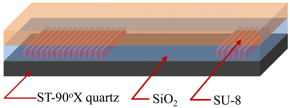
The purpose of this paper is to describes the Love wave propagation along the ST-90°X quartz substrate using a multi-guide structure like SiO2/SU-8, as shown in Figure 1. A SU-8 thin layer is proposed as guide layer, which exhibits low shear SH velocity, and benefits for the improvement of behavior and durability of a Love-type device when working as a viscosity sensor in liquid media [14,15].
A theoretical model was established to extract the optimal design parameters of the Love wave device with multi-guides by solving the coupled electromechanical field equation [11], and the temperature coefficient of frequency (Tcf) of such a Love wave structure was calculated theoretically. Then the theoretical results were confirmed by the experimental results, in which, a Love wave delay line with operation frequency of 174 MHz and SiO2/SU-8 guiding layer on ST-90°X quartz substrate was fabricated. Very excellent temperature stability of ∼2.16 ppm was observed from the fabricated Love wave device in case where 0.21 μm SiO2 and 0.8 μm SU-8 were coated as the guide layers.
2. Theoretical Analysis
2.1. Theory Model
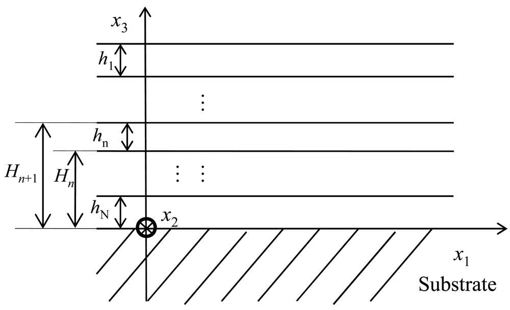
In this section, the temperature coefficient of frequency (Tcf) of a Love wave device with multi-guide layers was analyzed by solving the coupled electromechanical field equation combing with the approximate method described by Tomar et al. [11]. For the theoretical approach of the Love wave device, a layered structure composed of a semi-infinite piezoelectric substrate with IDT pattern, and multi-guide layers was constructed, as shown in Figure 2. In the present work the theoretical calculations on the layered structures is an application of the theory of elastic wave propagation developed by Farnell and Adler [16–18].
The coordinate system for the theoretical analysis of Love wave propagation along the layered structure is shown in Figure 2. All the parameters of the media are transformed into this coordinate system. It is well known that the constitutive equations in a piezoelectric medium are as follows:
Equations (3) and (4) can be used to eliminate the vectors S and E from the constitutive Equations (1) and (2). Gravity and other initial stresses in the medium are neglected, thus the particle motion satisfies Newton's law:
No external electric charges exist within the medium. Thus, the divergence of the electric displacement is zero:
For the analysis situation mentioned above, the particle motion and the electric field in such a piezoelectric medium satisfy the following equations:
(1) In the piezoelectric substrate
The substrate in this paper is a piezoelectric medium whose particle motion in the x2-direction is coupled with the electric field. The general solution assumed within the substrate is:
(2) In the elastic wave-guide layer
The particle displacement is uncoupled from the electric field within the layers because the layers are assumed to be isotropic materials without piezoelectricity. Suppose several layers were overlaid on the substrate, define the top layer the first one, the one above the substrate the Nth. The layer is finite in the x3-direction and the solution for acoustic waves in the nth layer is of the following form:
The electric potential in the nth layer can be expressed by:
(3) In the air or vacuum
Only electric potential exists in the air or vacuum, and the electric potential will be zero when x3→−∞, thus the solution for the electric potential above the guide layer is of the following form:
Mechanical boundary conditions: the particle displacement and stress in the x3-direction are continuous on every interface. The normal stress is zero on the surface of the top layer.
Electric boundary conditions: the electric potential and electric displacement in the x3-direction are continuous on every interface.
Hence, the dispersion equation of Love waves in a multi-waveguides structure can be obtained by the wave equations and the boundary conditions:
It is well-known that the material constants of the substrate and the layers vary with different temperature. Thus, the temperature-dependent Love wave phase velocity can be calculated using Equation (15) with temperature dependent material constants. The temperature coefficient of frequency (Tcf) can be defined as:
The temperature dependent material constants is approximated by a second-order function:
2.2. Numerical Results and Discussion
Here, we just consider the Love wave propagating along the multi-guiding layer on ST-90°X quartz, and the SiO2/SU-8 act as the wave guide layers, and the temperature-dependent mechanical parameters of the guiding layers and substrates like the density, elastic constants, piezoelectricity and dielectric constants of the above media are as listed in Table 2.
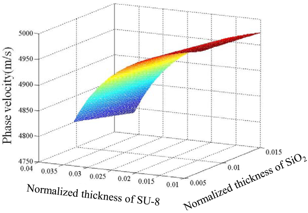
Based on the theoretical formulas mentioned above, and the mechanical parameters of the substrate and guide layers listed in Table 2, the dispersion properties of a Love wave in a layered structure can be analyzed, and the phase velocity of the Love wave depending on the guiding layer thickness at room temperature of 25 °C is as depicted in Figure 3. Only the fundamental Love wave mode exists under the thickness of waveguides we are interested in. From the calculated results, the Love wave velocity decreases with increases of the thickness of the guide layers, and the effect on the Love wave velocity from the SU-8 thickness was more obvious over the SiO2 guide layer.
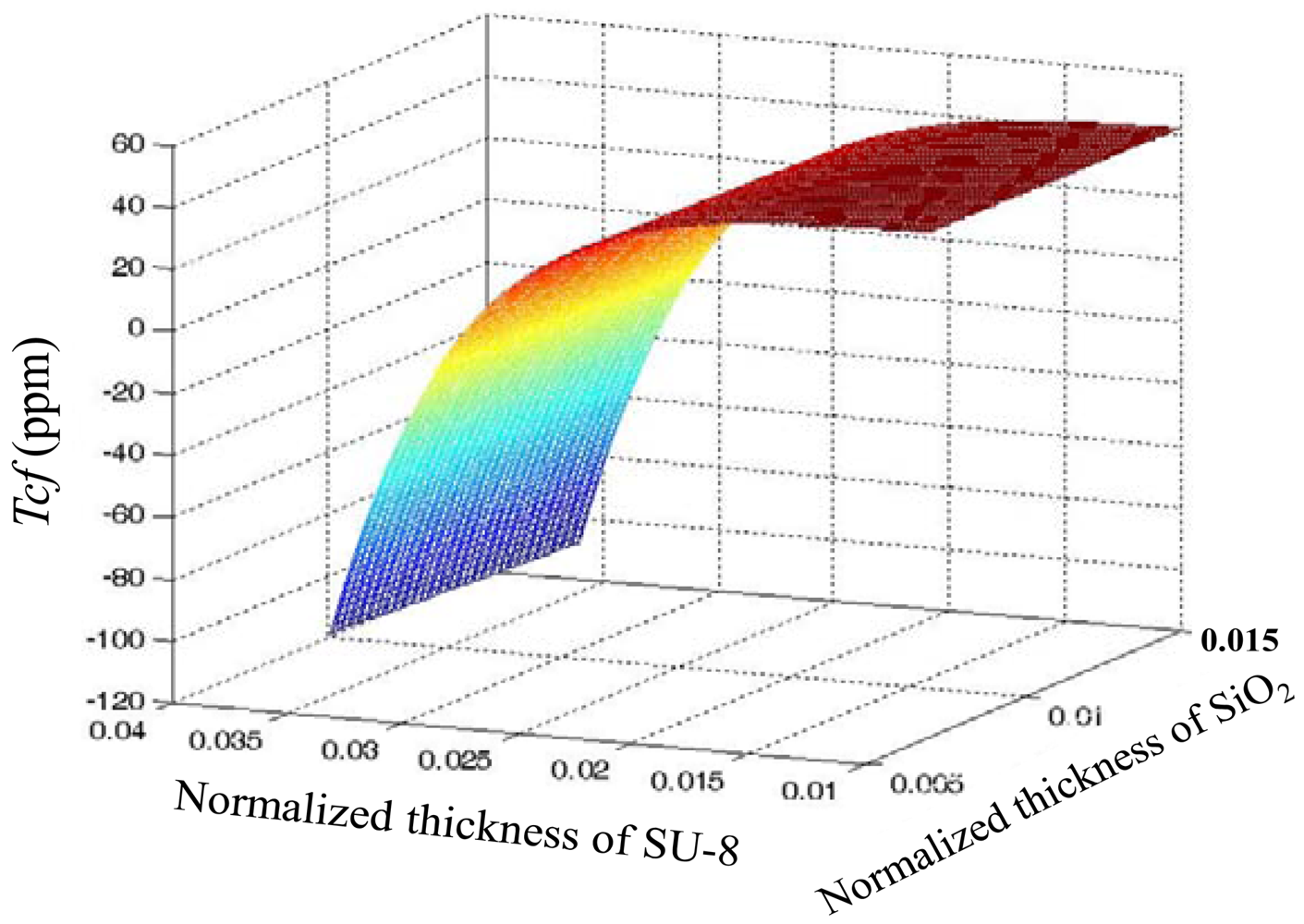
Figure 4 shows calculated Tcf versus normalized thickness of the guide layers in a layered structure of ST-90°X quartz/SiO2/SU-8 using Equation (20). The Tcf value is influenced by SU-8 thickness far more significantly than by that of SiO2. Considering the technical difficulties of thick SiO2 film deposition, a thin SiO2 coating is advised, so, from Figure 3, we can see that when the thickness of SiO2 is 0.2 μm and SU-8 0.826 μm are applied; almost zero Tcf of the device may be achieved.
3. Experiments
3.1. Fabrication of the Love Wave Device
The Love wave delay lines with a SiO2/SU-8 guiding layer were developed on a ST-90°X quartz substrate. First the SH-SAW delay line on ST-90°X quartz with two photolithographically defined Al (250 nm) transducers separated by a path length (transducer center separation) of 2.5 mm was fabricated. The two transducers consist of 120 and 40 finger-pairs interdigitated electrodes, with periodicity of 28 μm for an operation frequency of 175 MHz. A single phase unidirectional transducer (SPUDT) was used to structure the transducers to reduce the low insertion loss [21]. Then, SiO2 thin film was evaporated on the fresh surface of the SH-SAW device by the lift-off technique at room temperature with a sacrificial layer of photoresist 5214. The thickness of SiO2 was set to 0.21 μm according to the theoretical prediction, and monitored by an Alpha-Step IQ profiler. After the SiO2 coating, the SU-8 2050 with various thicknesses produced by the Microchem Company was deposited onto the SiO2 surface by spin coating. The design parameters of the fabricated devices are as listed in Table 3.
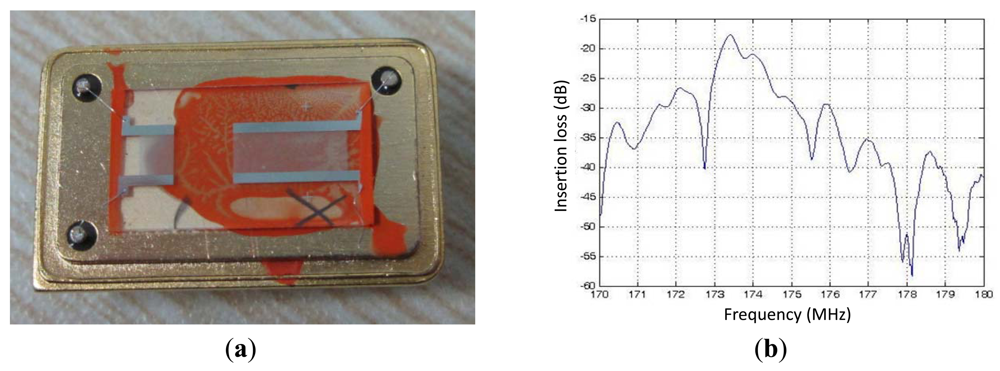
Figure 5(a) shows the fabricated Love wave devices with size of 9 × 3 mm, and also, the frequency response (S21) of the fabricated Love wave device with SU-8 thickness of 0.8 μm, tagged as device #1, which was characterized by a network analyzer (Advantest R3765), as shown in Figure 5(b). Insertion loss of ∼17dB was observed at the frequency of 173.38 MHz.
3.2. Experimental Setup
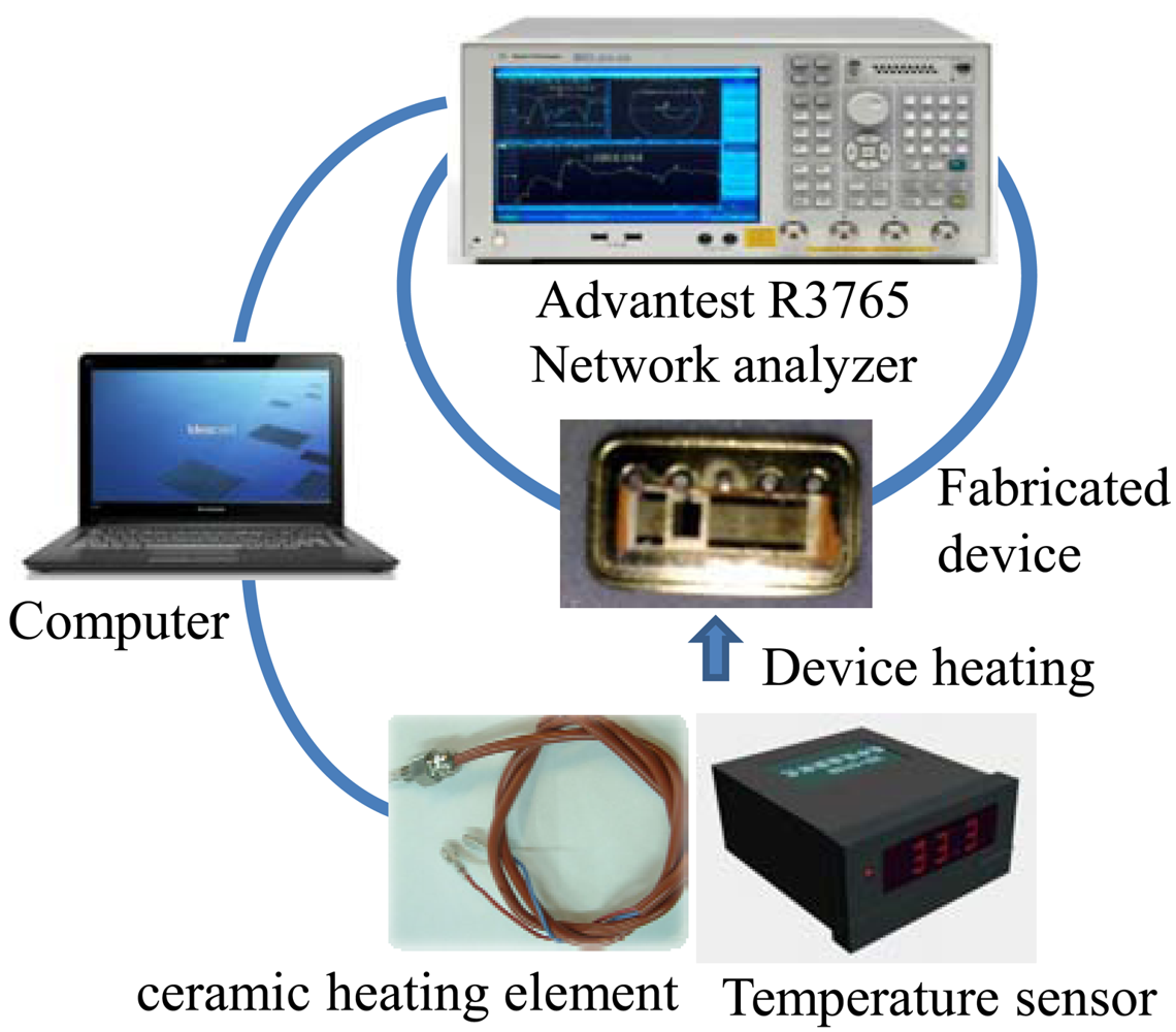
The temperature properties of the fabricated Love wave devices were evaluated experimentally. The measurement setup, which includes the network analyzer, temperature sensor, ceramic heating element and computer, is depicted in Figure 6. The fabricated Love wave delay lines with different SU-8 thicknesses listed in Table 2 were heated by the ceramic heating element, and the network analyzer was used to monitor and recording the frequency shift depending on the applied temperature change. The temperature change of the Love wave device is also read out by the temperature sensor connected to pt100 posted at the bottom of the Love wave device. Both frequency and temperature are acquired in real time by the PC connected to network analyzer and temperature sensor.
3.3. Experimental Results and Discussion
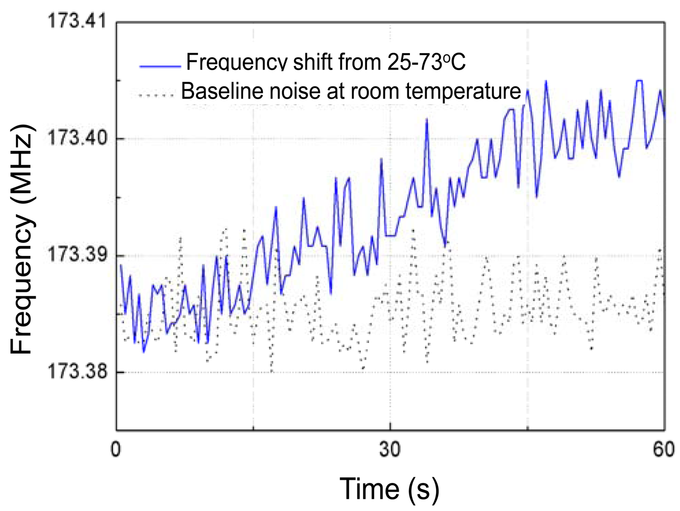
Prior to measurement, the baseline noise of the Love wave device in testing time of 60 s was tested at room temperature (25 °C). It is shown as the dotted line in Figure 7. A frequency shift of ∼10 kHz was observed.
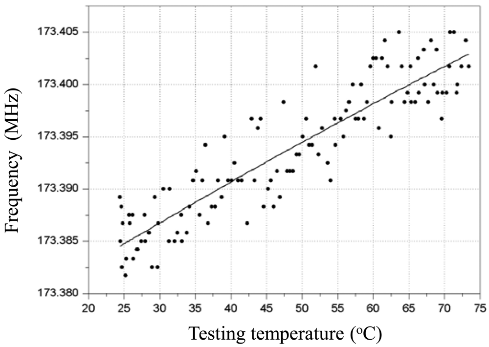
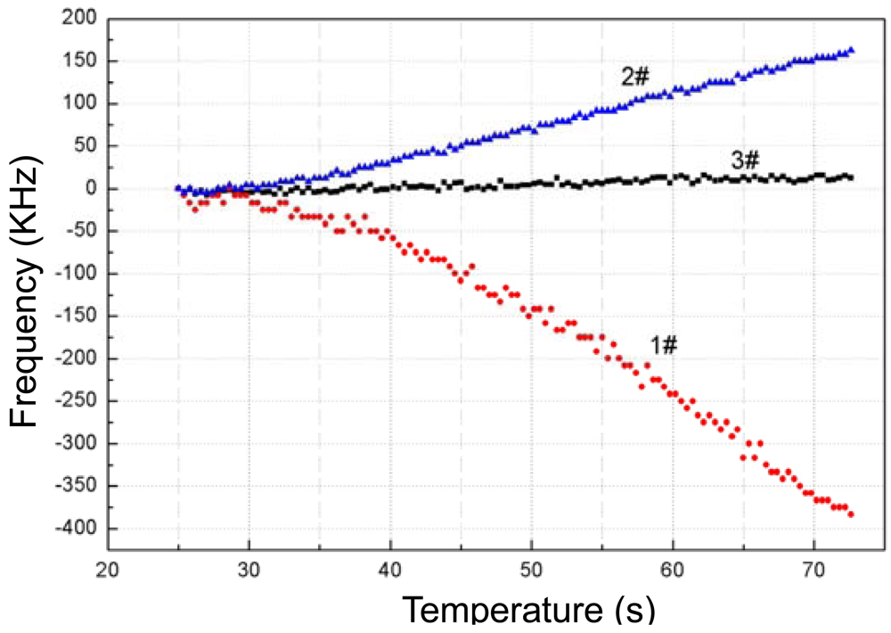
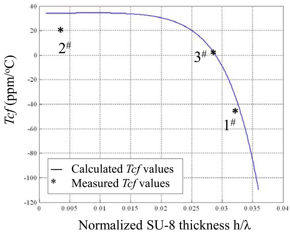
Then, the frequency response depending on temperature variation from 25 °C to 73 °C of the fabricated Love wave delay line (device #3) was measured as shown in Figure 7, and a frequency shift of around 0.018MHz with a temperature increase of 48 °C was observed. The binomial fitting of the measured frequency shift in temperature range of 25 °C∼73 °C was plotted in Figure 8. A very low Tcf of 2.16 ppm/°C (Tcf = 0.018/48/173.38 × 106) was deduced experimentally, and it is far more less than typical Love wave structure (ST-90°X quartz/SiO2) of 27–31 ppm/°C [8]. Also, due to the insertion loss effect due to strain, and the stress effect between the SU-8 and SiO2 layers as temperature increases, another insertion loss of ∼5 dB was induced when the temperature was increased to 73 °C. The temperature properties of another two devices (device 1# and 2#) in the temperature range of 25 °C∼73 °C were also tested as shown in Figure 9, and the corresponding Tcf values for the device 1# and 2# sre depicted in Figure 10.
The measured data agrees well with the theoretical analysis as above. When thicker SU-8 was applied, the frequency decreases quickly due to the larger viscoelastic nature of the polymer itself. It means that the optimal thicknesses of the multi-guide layers of SiO2/SU-8 are determined as 0.21 μm/0.8 μm. From these promising results, we conclude that the temperature stability of a Love wave device can be improved effectively by controlling the wave guide layer thickness.
4. Conclusions
The temperature effect on Love wave propagation along a layered structure was analyzed theoretically. The Love wave device with multi-guide layers of SU-8/SiO2/ST-90°X quartz and a very low temperature coefficient of frequency (Tcf) of 2.16 ppm/°C was implemented based on establishment of the corresponding theoretical model. The optimal guide layer thicknesses were determined, leading to excellent temperature stability. The theoretical model was confirmed by the experiments.
Acknowledgments
The authors gratefully acknowledge the support of the National Natural Science Foundation of China: No. 11074268 and 10974171.
References
- Gizeli, E. Design considerations for the acoustic waveguide biosensor. Smart Mater. Struct. 1997, 6, 700–706. [Google Scholar]
- Kovacs, G.; Vellekoop, M.J.; Haueis, R. A love wave sensor for (bio)chemical sensing in liquids. Sens Actuators A 1994, 43, 38–43. [Google Scholar]
- Gizeli, E.; Bender, F.; Rasmusson, A. Sensitivity of the acoustic wave guide biosensor to protein binding as a function of thewaveguide properties. Biosens. Bioelectron. 2003, 18, 1399–1406. [Google Scholar]
- Zimmermann, C.; Rediere, D.; Dejous, C. A love-wave gas sensor coated with functionalized polysiloxane for sensing organophosphorus compounds. Sens Actuators B 2001, 76, 86–94. [Google Scholar]
- Jakoby, B.; Ismail, G.M.; Byfield, M.P. A novel molecularly imprinted thin film applied to a Love wave gas sensor. Sens Actuators A 1999, 76, 93–97. [Google Scholar]
- Bender, F.; Cernosek, R.W.; Josse, F. Love-wave biosensors using cross-linked polymer wave guides on LiTaO3 substrates. Electron. Lett. 2000, 36, 1672–1673. [Google Scholar]
- Wang, W.; He, S. Theoretical analysis on response mechanism of polymer-coated chemical sensor based Love wave in viscoelastic media. Sens Actuators B 2009, 138, 432–440. [Google Scholar]
- Du, J.; Harding, G.L.; Ogilvy, J.A. A study of Love-wave acoustic sensors. Sens Actuators A 1996, 56, 211–219. [Google Scholar]
- Du, J.; Harding, G.L. A multilayer structure for Love-mode acoustic sensors. Sens Actuators A 1998, 65, 152–159. [Google Scholar]
- Hickernell, F.S.; Knuth, H.D.; Dablemont, R.C. The Surface Acoustic Wave Propagation Characteristics of 41° Lithium Niobate with Thin Film SiO2. Proceeding of IEEE International Frequency Control Symposium, Honolulu, HI, USA, 5–7 June 1996; pp. 216–221.
- Tomar, M.; Gupta, V.; Mansingh, A. Temperature stability of c-axis oriented LiNbO3/SiO2/Si thin film layered structures. J. Phys. D: Appl. Phys. 2001, 34, 2267–2273. [Google Scholar]
- Tomar, M.; Gupta, V.; Sreenivas, K. Temperature coefficient of elastic constants of SiO2 over-layer on LiNbO3 for a temperature stable SAW device. J. Phys. D: Appl. Phys. 2003, 36, 1773–1777. [Google Scholar]
- Parker, T.E.; Schulz, M.B. SiO2 film overlays for temperature−stable surface acoustic wave devices. Appl. Phys. Lett. 1975, 26, 75–77. [Google Scholar]
- Roach, P.; Atherton, S.; Doy, N. SU-8 guiding layer for love wave devices. Sensors 2007, 7, 2539–2547. [Google Scholar]
- Lee, S.; Kim, K.-B.; Kim, Y., II. Love wave SAW biosensors for detection of antigen-antibody binding and comparison with SPR biosensor. Food Sci. Biotechnol. 2011, 20, 1413–1418. [Google Scholar]
- Auld, B.A. Acoustic Resonators. In Acoustic Fields and Waves in Solids, 2nd ed.; John Wiley & Sons, Inc.: New York, NY, USA, 1973; Volume 1, pp. 265–348. [Google Scholar]
- Farnell, G.W. Symmetry Considerations for Elastic Layer Modes Propagating in Anisotropic piezoelectric Crystal. IEEE Trans. Sonics Ultrason. 1970, 17, 229–238. [Google Scholar]
- Liu, J.S.; He, S.T. Properties of Love waves in layered piezoelectric structures. Int. J. Solids Struct. 2010, 47, 169–174. [Google Scholar]
- Zhang, G.W.; Shi, W.K.; Ji, X.J. Temperature Characteristics of Surface Acoustic Waves Propagating on La3Ga5SiO4 Substrates. J. Mater. Sci. Technol. 2004, 20, 63–66. [Google Scholar]
- MPDB software. Material Property Database [DB/OL]. Available online: http://www.jahm.com/ (accessed on 24 May 2012).
- Wang, W.; He, S.T.; Li, S.Z. Enhanced sensitivity of SAW gas sensor coated molecularly imprinted polymer incorporating high frequency stability oscillator. Sens Actuators B 2007, 125, 422–427. [Google Scholar]
| Materials | Shear Velocity (m/s) | Density (kg/m3) | Polarity of Temperature Coefficient |
|---|---|---|---|
| 64efficien3 | 4,608 | 4,700 | - |
| 41efficien3 | 4,792 | ||
| 3600ficien3 | 4,202 | 7,450 | - |
| ST-90ic quartz | 5,060 | 2,650 | + |
| 36artquartz | 5,100 | ||
| SiO2 | 2,850 | 2,650 | + |
| PMMA | 1,100 | 1,140 | - |
| SU-8 | 1,810 | 1,190 | - |
| Materials | Parameters | X0 at reference temperature of T0 | α1 (10−4) | α2 (10−7) |
|---|---|---|---|---|
| Quartz | c11(1011 N/m2) | 0.8674 | −0.443 | −4.07 |
| T0 = 20 °C | c12(1011 N/m2) | 0.0699 | −29.3 | 72.45 |
| c13(1011 N/m2) | 0.1191 | −4.92 | −5.96 | |
| c14(1011 N/m2) | −0.1791 | 0.98 | −0.13 | |
| c33(1011 N/m2) | 1.072 | −1.88 | −14.12 | |
| c44(1011 N/m2) | 0.5794 | −1.72 | −2.25 | |
| c66(1011 N/m2) | 0.3988 | 1.8 | 2.01 | |
| ρ(103 kg/m3) | 2.65 | −0.3492 | −0.159 | |
| e11(C/m2) | 0.171 | |||
| e14(C/m2) | 0.0403 | |||
| ε11(10−11 F/m2) | 3.997 | |||
| ε33(10−11 F/m2) | 4.103 | |||
| α11(10−6 /°C) | 13.71 | |||
| α33(10−6 /°C) | 7.48 | |||
| SiO2 | ρ(103 kg/m3) | 2.2 | ||
| T0 = 25 °C | μ(1011 N/m2) | 0.3121 | 1.4553 | |
| ε11(10−11 F/m2) | 3.8265 | 0.2628 | ||
| SU-8 | ρ(103 kg/m3) | 1.2152 | −4.5142 | 1.3302 |
| T0 = 25 °C | μ(1011 N/m2) | 0.011769 | 83.3139 | |
| ε11(10−11 F/m2) | 2.6563 | −37.757 | ||
| Device # | SiO2 Thickness (μm) | SU-8 Thickness (μm)/(h/λ) |
|---|---|---|
| 1 | 0.21 | 0.9/0.032 |
| 2 | 0.21 | 0.1/0.0035 |
| 3 | 0.21 | 0.8/0.028 |
© 2012 by the authors; licensee MDPI, Basel, Switzerland. This article is an open access article distributed under the terms and conditions of the Creative Commons Attribution license (http://creativecommons.org/licenses/by/3.0/).
Share and Cite
Xu, F.; Wang, W.; Hou, J.; Liu, M. Temperature Effects on the Propagation Characteristics of Love Waves along Multi-Guide Layers of Sio2/Su-8 on St-90°X Quartz. Sensors 2012, 12, 7337-7349. https://doi.org/10.3390/s120607337
Xu F, Wang W, Hou J, Liu M. Temperature Effects on the Propagation Characteristics of Love Waves along Multi-Guide Layers of Sio2/Su-8 on St-90°X Quartz. Sensors. 2012; 12(6):7337-7349. https://doi.org/10.3390/s120607337
Chicago/Turabian StyleXu, Fangqian, Wen Wang, Jiaoli Hou, and Minghua Liu. 2012. "Temperature Effects on the Propagation Characteristics of Love Waves along Multi-Guide Layers of Sio2/Su-8 on St-90°X Quartz" Sensors 12, no. 6: 7337-7349. https://doi.org/10.3390/s120607337


