Microfiber-Based Bragg Gratings for Sensing Applications: A Review

Abstract
: Microfiber-based Bragg gratings (MFBGs) are an emerging concept in ultra-small optical fiber sensors. They have attracted great attention among researchers in the fiber sensing area because of their large evanescent field and compactness. In this review, the basic techniques for the fabrication of MFBGs are introduced first. Then, the sensing properties and applications of MFBGs are discussed, including measurement of refractive index (RI), temperature, and strain/force. Finally a summary of selected MFBG sensing elements from previous literature are tabulated.1. Introduction
Fiber Bragg gratings (FBGs) are periodic modulations of the refractive index (RI) along the fiber length. Since their discovery in 1978 [1], FBGs have been widely used as a sensing element in areas including temperature monitoring, strain sensing, rotation sensing, and underwater acoustic sensing. In fact, fiber-based techniques provide a technology which can produce sensors that are immune to electromagnetic interference, inherent self-referencing, lightweight, easily multiplexable, and in most cases have the potential to be produced at low cost. Over the last two decades, FBGs have been manufactured mainly by modifying the core refractive index using interferometric or point-by-point techniques. Most of the interferometric techniques use a phase mask and an ultraviolet (UV) laser [2], typically an excimer laser or a frequency doubled Ar+ ion laser. Moreover, FBGs are typically several millimeters long and a hundred micrometers thick. The large size limits its performance and its use in some special applications such as RI sensing and detection of ultra-small objects.
Recently, microfibers (MFs) have attracted great attention because of their low loss, large evanescent fields, strong confinement, configurability, and robustness [3,4]. MFs have found potential applications in a wide range of fields from telecommunications to sensors, and lasers [5–21]. Because of their large evanescent field and micrometer-scale size, MFs are seen as useful tools to exploit FBGs as refractive index sensors and to reduce their size. Initially, microfiber-based Bragg gratings (MFBGs) have been fabricated by etching away the fiber cladding after writing the grating in the photosensitive core [22–25] or by UV irradiation on the MF drawn from a fiber preform [26–30]. Yet, to shorten the grating length and reduce its size, strong RI modulations (∼10−3−10−1) are necessary. Strong RI modulations can be obtained alternating layers of materials with high contrast RI, such as glass and air. For a normal optical fiber, this process requires the removal of large amounts of material (the propagating mode is confined at a depth > 50 μm from the fiber surface). On the contrary, for a MF, it only requires the removal of small amounts of fused silica because the modal field is comparable to or larger than the MF cross section. MFBGs with strong RI modulation can be fabricated using focused ion beam (FIB) milling [31–38] and can be as short as ∼101–102 μm.
This review will mainly focus on MFBGs written in MFs with diameters smaller than 10 μm. This paper is organized as follows. Fabrication of MFBGs is shown in Section 2. Section 3 is dedicated to the discussion of the MFBGs fundamental characteristics and sensing properties. Section 4 is devoted to the sensing applications previously reported in the literature. Finally, conclusions and future prospects of MFBGs are given in Section 5.
2. Fabrication of MFBGs
Several techniques have been reported in the literature for the fabrication of FBGs on MFs and they can be classified as follows:
Both cladding-etched commercial FBGs and UV irradiated FBGs in MFs are uniform MFBGs (uMFBGs), meaning that the grating region experiences only RI modulation and not structural perturbations as indicated in Figure 1.
The most commonly used technique to get an uMFBG is to etch a single mode fiber (SMF) after the FBG has been written in the photosensitive Ge-doped core [22–25]. Usually, a hydrofluoric acid aqueous solution (∼20%–50%) at room temperature is employed for the etching process at an etching speed of ∼0.5–2 μm/min. The diameter of the etched fiber could be measured and controlled in situ by monitoring the transmission loss.
2.1. Etch-Eroded Commercial FBGs or UV Irradiated FBGs
An alternative way is to use a 248 nm KrF excimer laser and a uniform phase mask to inscribe FBG in MFs drawn from 125 μm-diameter fibers [26,27]. The preform fibers are usually highly Ge-doped and have large cores to guarantee that the MFs have a large enough photosensitive cross section. Sometimes, hydrogen loading treatment are further employed to increase the photosensitivity [27]. However, during the hydrogen loading treatment, high pressures and temperatures are needed, which complicates the procedure [27].
To avoid additional hydrogen loading or photosensitization treatments, Ran et al. used a 193 nm ArF excimer laser and phase mask to inscribe strong FBG in MFs drawn from both standard telecom SMF [28] and 62.5/125 μm multimode fiber (MMF) [29]. This method utilizes the high efficiency associated with two-photon excitation at 193 nm [30].
2.2. FIB-Milled MFBGs
FIB milling, a powerful micromachining technique, has also been used to fabricate MFBGs [31–38]. This method employs accelerated ions to mill nanometer-scale features on MF surfaces to form corrugated structures. As the index modulation results from changes in the structure, this kind of gratings are called structural MFBGs (sMFBGs).
Prior to the milling, the MF is coated with a thin film of metal, e.g., aluminum or gold [31–35], to prevent charge accumulation which cause ion deflections and large fabrication errors. Alternatively, MF can also be laid on a doped silicon wafer [36]: due to van der Waals' forces, the MF tightly attaches to the conductive substrate and it avoids charging by transferring charges to the wafer.
During the FIB micromachining process, the MF sample should be fixed firmly in the vacuum chamber to minimize sample displacements. A 30 kV, 10–300 pA Ga+ ion beam is usually used to get enough milling accuracy depending on different FIB systems. The total milling process takes minutes to hours according to the beam current used and milling area. After the machining process, for a nonmetallic sMFBG, the MF is immersed in metal etchant to totally remove the metal film and then is cleaned with deionized water.
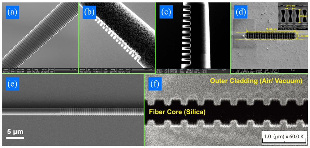
Figure 2 shows FIB/SEM pictures of sMFBGs fabricated from different groups. Gratings in Figure 2(a–c) are fabricated on MF tips while the rest are on tapers. The sMFBGs are fabricated on MFs with diameter ranging from 560 nm (Figure 2(f)) to 6.6 μm (Figure 2(a)) and the number of period of the gratings varies from 11 (Figure 2(c)) to 900 (Figure 2(e)). Both high (5 × 10⁻³−10−1, Figure 2(c,d,f)) and low (10−4−5 × 10⁻³, Figure 2(a,b,e)) average RI modulations have been achieved by FIB-milled sMFBG. In all, FIB provides researchers a flexible way to get all kinds of structures with high accuracy at will and without additional masks. Yet, batch production cannot be envisaged for this method.
2.3. Femtosecond-Laser-Irradiated MFBGs
Femtosecond-laser-irradiation is another way to cause periodically physical deformation on the surface of MFs [40]. During the femtosecond laser irradiation, the ultra-short laser pulse transfers energy to the electrons in the material irradiated through nonlinear ionization [45]. When a sufficiently high energy is achieved, pressure or shock wave will cause melting or non-thermal ionic motion, resulting in permanent structural damages in the material. Aided with proper phase masks, MFBGs can be fabricated on the surface of the MFs [39,40].
2.4. Other Techniques
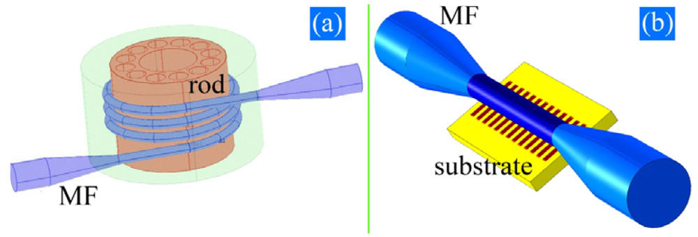
In addition to the previous techniques, other methods have also been demonstrated or proposed. MFBGs can be manufactured by wrapping a MF on a microstructured rod with an internal channel (see Figure 3(a)) or by laying the MF on a substrate with pre-treated microstructures (see Figure 3(b)). By exploiting the fraction of power propagating in the periodically distributed patterns in the rod or the substrate, light transmission could be modulated. This compact scheme of Figure 3(a) can be used as a RI sensor when the evanescent field extends in the inner fluidic channel. Both methods avoid post-processing the thin MFs and have great flexibility. However, the MFs have to be coated with low index polymer [46] which means that they are not suitable for high temperature sensing.
Ding et al. [42] combined metal lift-off technology with lithography to produce metallic surface gratings, which provided a high and constant sensitivity to the ambient medium RI, while Phan Huy et al. [43] demonstrated an improvement in the sensitivity of RI by making use of the suspended core of a microstructured fiber.
3. Fundamental Characteristics and Sensing Properties of MFBGs
3.1. Fundamental Characteristics of MFBGs
In the grating, the forward (f) and backward (b) propagating modes are related by
Furthermore, if the two modes are identical, the commonly used Bragg resonance condition can be obtained, namely, λB = 2neffΛ.
Before designing the grating, neff should be calculated first. For a uMFBG, the index modulation is relatively weak (usually on the order of 10−4) and the cross section of the MF is a symmetrical circle. neff can be easily obtained solving the dispersion equations numerically.
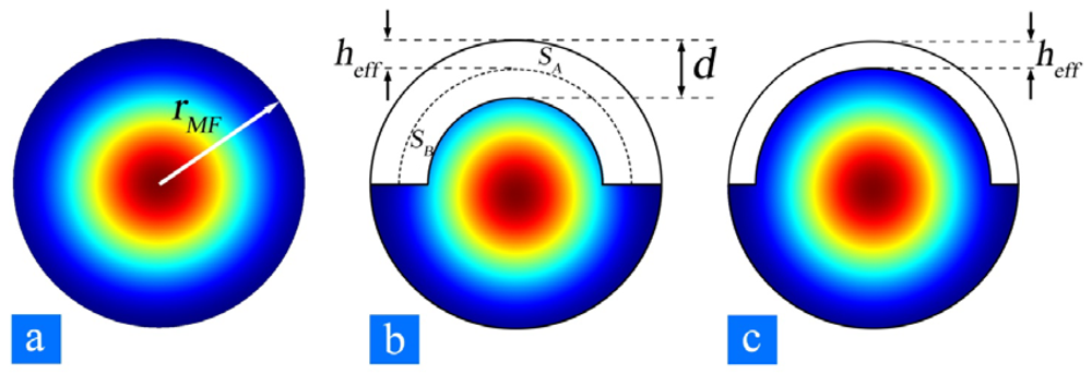
However, for a sMFBG, the effective index difference between the MF milled and un-milled cross section can be as large as ∼10−3 [31], or even ∼10−1 [34], orders of magnitude larger than that in conventional FBGs. One way to calculate an averaged effective index of the grating region is to choose an unperturbed waveguide boundary [48], shown as the curved dashed line in Figure 4(b). d is the depth of the corrugation and heff is the boundary shift from the top of the corrugation to the new boundary of the corresponding unperturbed waveguide. The boundary shift heff as illustrated in Figure 4(b,c) is determined such that the volume bounded by the upper part of the corrugation (SAτ) is equal to that of the volume bounded below [SB(1−τ)], i.e.,
The uMFBGs reflection spectrum can be estimated using [49]
However, due to the large index difference in the corrugation region in sMFBGs, strong scattering may occur. A more effective way to verify the experimental spectrum obtained from the sMFBG is a 3D finite element simulation, shown in Figure 5. This method takes the details of the structural deformation into consideration and thus better reflects the real situation experienced by the light field.
3.2. Sensing Properties of MFBGs
Most MFBG sensors rely on the monitoring of the shift in wavelength of the reflected Bragg signal with the changes in the measurand (e.g., refractive index, temperature, and strain/force).
As the effective index and period of grating is a function of rMF, na, T, and ε, the Bragg condition can be rewritten as
3.2.1. Refractive Index Sensing
The notable distinction between MFBGs and conventional FBGs lies in that the MFBG large evanescent field which enables its capabilities for external medium sensing. When a MFBG is operated as a RI sensor, the wavelength shift depends on the change of na. Sensitivity with respect to the ambient medium RI (Sa) is defined as
3.2.2. Temperature Sensing
Temperature affects the Bragg wavelength shift through the thermo-optical and thermal expansion effects in three ways: index variation, MF radius variation and the grating period change, each of which is represented in Equation (7). The temperature sensitivity (ST) can be defined as:
Here, σT (1.2 × 10⁻⁵/°C) is the thermo-optical coefficient and αT (5.5 × 10⁻⁷/°C) is the thermal expansion coefficient of fused silica. As thermal expansion contributes less than 2 pm/°C to the total sensitivity, it is generally neglected. ST resulting from the thermo-optical effect is ∼10–20 pm/°C and dominates in temperature sensing, which is in agreement with previous results using fiber tip Febry-Perot interferometer [9].
3.2.3. Strain/Force Sensing
From the continuum mechanics, when longitudinal strain is applied to a MFBG, wavelength shift can be estimated as follows:
The effective photo-elastic coefficient peff for a MFBG strain sensor is ∼0.21, giving SS ∼1.2 pm/με which is compared to that of a conventional fiber at a Bragg wavelength of 1550 nm. This is in agreement with experimental results [24,26]. Another way to characterize the capability of MFBG sensors is to use the force sensitivity (SF):
4. Sensing Applications
4.1. Refractive Index Sensing
Much of the MFBG applications relate to RI sensing. For a typical MFBG sensor immersed in ambient liquid with RI in the range 1.32–1.46, Sa varies from 101 nm/RIU (refractive index unit) to 103 nm/RIU, according to the MF radius and the ambient liquid sensed. Usually, a smaller radius and a larger ambient medium RI result in a higher sensitivity regardless of the fabrication method. For example, Liang et al. got a sensitivity of 16 nm/RIU at a RI around 1.35 with a MF 6 μm in diameter [22] while 660 nm/RIU was reached by Liu et al. at a RI of 1.39 by using a 1.8 μm-diameter MF [36]. Both of them agree well with what is predicted from Equation (6). Significant results previously reported in the literature are listed in Table 1.
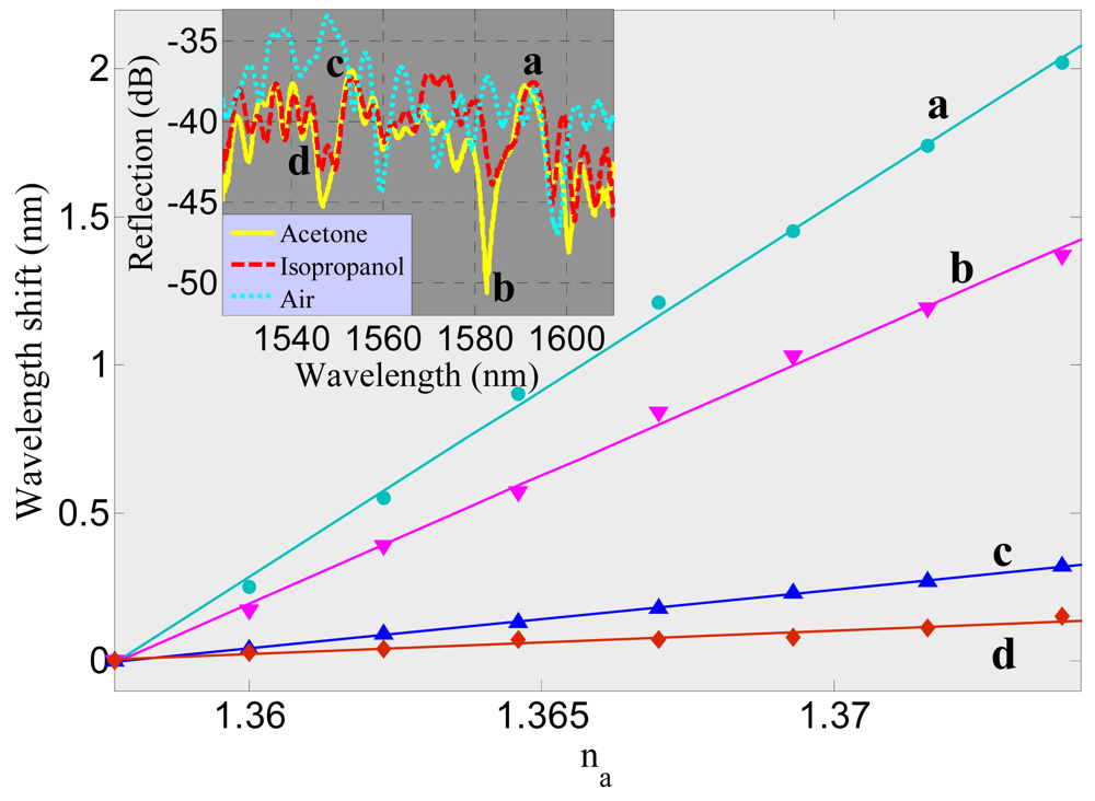
In addition to all these nonmetallic MFBGs, metallic gratings have also been proposed for RI sensing. The existence of metal causes light to be coupled to modes of different properties [32,42]. A metal-dielectric-hybrid grating (Figure 2(b)) showed RI sensitive (a in Figure 7) and insensitive (d in Figure 7) behavior for different resonant modes (see inset of Figure 7) [32]. Sa of the sensitive channel (125 nm/RIU) is one order of magnitude larger than that of a nonmetallic MFBG with the same radius whereas Sa of the insensitive channel (8 nm/RIU) is one order of magnitude smaller. This can be attributed to the fact that the introduction of metal film causes the MF to support both surface guided modes (which have a larger modal overlap with the ambient medium, Figure 7(a,b)) and bound modes (where most of the energy is located in the dielectric core, Figure 7(c,d)).
4.2. Temperature Sensing
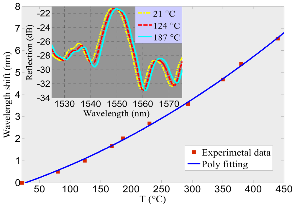
Although thermal post-processing and hydrogen loading have been shown to induce grating capable of standing temperatures as high as 1,300 °C in conventional fibers [52]; for uFMBGs, only small temperature ranges have been detected because the photosensitized index modulation is unstable at high temperatures. In MF thermometers, up to now, only sMFBGs have been reported operating above 200 °C [31,35]. The sensitivity of these components is around 20 pm/°C, similar to the value predictable using Equation (7). Figure 8 is the experimental characterization of the sFMBG demonstrated using the sample shown in Figure 2(a). As the temperature increases, the Bragg wavelength red shifts. The extremely short length of the MFBG (∼36.6 μm) and wide operating range (∼20–450 °C) presents it a promising candidate for detecting temperature change in ultra-small spaces.
4.3. Strain/Force Sensing
Although SS remains almost the same for different MF diameters [26], SF varies with the MF radius according to Equation (10). A MFBG with diameter of 3.5 μm reaches a force sensitivity of ∼1900 nm/N, which is more than three orders of magnitude compared to that of a conventional fiber [26]. If the Bragg wavelength can be detected to an accuracy of 0.05 nm, it would be possible to measure forces in the order of 10−5 N. For the sample reported in Figure 2(d), where the silica constitute only a small fraction of the MFBG cross section, a further three orders of magnitude improvement in sensitivity is predicted, with SF reaching values in excess of 106 nm/N, corresponding to forces of the order of nN. The MFBG strain/force sensors could offer attractive properties monitoring strain/force changes in power plant pipelines, airplane wings, and other civil engineering structures.
5. Conclusions and Outlook
MFBGs can potentially outperform conventional FBGs because of their large evanescent field and compactness. This review presented the fabrication, operating principles and applications of MFBGs. Due to their ultra-small size (especially the sMFBGs), MFBGs could find promising sensing applications in detecting parameter variations in ultra-small spaces.
Future work may focus on (1) expanding the MFBG to simultaneous multi-parameter measurement, such as using the metal-dielectric-hybrid grating; (2) utilizing MFBG to operate in extreme temperatures as high as 1,500 °C; (3) studying sMFBG for strain/force sensing applications; (4) taking advantage of other materials to increase ST, which is now mainly limited by the thermo-optical coefficient of silica.
Acknowledgments
Fei Xu and Yanqing Lu acknowledge the support from National 973 program under contract No. 2011CBA00200 and 2012CB921803, NSFC program No. 11074117 and 60977039, and the Priority Academic Program Development of Jiangsu Higher Education Institutions (PAPD). Gilberto Brambilla gratefully acknowledges the Royal Society (London, UK) for his University Research Fellowship.
References
- Hill, K.O.; Fujii, Y.; Johnson, D.C.; Kawasaki, B.S. Photosensitivity in optical fiber waveguides: Application to reflection filter fabrication. Appl. Phys. Lett. 1978, 32, 647–649. [Google Scholar]
- Hill, K.O.; Malo, B.; Bilodeau, F.; Johnson, D.C.; Albert, J. Bragg gratings fabricated in monomode photosensitive optical fiber by UV exposure through a phase mask. Appl. Phys. Lett. 1993, 62, 1035–1037. [Google Scholar]
- Tong, L.; Gattass, R.R.; Ashcom, J.B.; He, S.; Lou, J.; Shen, M.; Maxwell, I.; Mazur, E. Subwavelength-diameter silica wires for low-loss optical wave guiding. Nature 2003, 426, 816–819. [Google Scholar]
- Brambilla, G. Optical fibre nanowires and microwires: A review. J. Opt. 2010. [Google Scholar] [CrossRef]
- Jung, Y.; Brambilla, G.; Richardson, D.J. Optical microfiber coupler for broadband single-mode operation. Opt. Express 2009, 17, 5273–5278. [Google Scholar]
- Xu, F.; Horak, P.; Brambilla, G. Optical microfiber coil resonator refractometric sensor. Opt. Express 2007, 15, 7888–7893. [Google Scholar]
- Xu, F.; Horak, P.; Brambilla, G. Optical microfiber coil resonator refractometric sensor: Erratum. Opt. Express 2007, 15, 9385–9385. [Google Scholar]
- Xu, F.; Pruneri, V.; Finazzi, V.; Brambilla, G. An embedded optical nanowire loop resonator refractometric sensor. Opt. Express 2008, 16, 1062–1067. [Google Scholar]
- Kou, J.-L.; Feng, J.; Ye, L.; Xu, F.; Lu, Y.-Q. Miniaturized fiber taper reflective interferometer for high temperature measurement. Opt. Express 2011, 18, 14245–14250. [Google Scholar]
- Kou, J.-L.; Feng, J.; Wang, Q.-J.; Xu, F.; Lu, Y.-Q. Microfiber-probe-based ultrasmall interferometric sensor. Opt. Lett. 2011, 35, 2308–2310. [Google Scholar]
- Leon-Saval, S.; Birks, T.; Wadsworth, W.; Russell, P.St.J.; Mason, M. Supercontinuum generation in submicron fibre waveguides. Opt. Express 2004, 12, 2864–2869. [Google Scholar]
- Ding, M.; Wang, P.; Brambilla, G. A microfiber coupler tip thermometer. Opt. Express 2012, 20, 5402–5408. [Google Scholar]
- Wang, P.; Brambilla, G.; Ding, M.; Semenova, Y.; Wu, Q.; Farrell, G. High-sensitivity, evanescent field refractometric sensor based on a tapered, multimode fiber interference. Opt. Lett. 2011, 36, 2233–2235. [Google Scholar]
- Brambilla, G.; Xu, F.; Horak, P.; Jung, Y.; Koizumi, F.; Sessions, N.P.; Koukharenko, E.; Feng, X.; Murugan, G.S.; Wilkinson, J.S.; Richardson, D.J. Optical fiber nanowires and microwires: Fabrication and applications. Adv. Opt. Photon. 2009, 1, 107–161. [Google Scholar]
- Chen, Y.; Xu, F.; Lu, Y.-Q. Teflon-coated microfiber resonator with weak temperature dependence. Opt. Express 2011, 19, 22923–22928. [Google Scholar]
- Qiu, S.-J.; Chen, Y.; Kou, J.-L.; Xu, F.; Lu, Y.-Q. Miniature tapered photonic crystal fiber interferometer with enhanced sensitivity by acid microdroplets etching. Appl. Opt. 2011, 50, 4328–4332. [Google Scholar]
- Kou, J.-L.; Xu, F.; Lu, Y.-Q. Highly Birefringent Slot-Microfiber. IEEE Photon. Technol. Lett. 2011, 23, 1034–1036. [Google Scholar]
- Kou, J.-L.; Guo, W.; Xu, F.; Lu, Y.-Q. highly birefringent optical-fiberized slot waveguide for miniature polarimetric interference sensors: A proposal. IEEE Sens. J. 2012, 12, 1681–1685. [Google Scholar]
- Liang, R.; Sun, Q.; Wo, J.; Liu, D. Investigation on micro/nanofiber Bragg grating for refractive index sensing. Opt. Commun. 2011, 285, 1128–1133. [Google Scholar]
- Zhang, A.; Gao, S.; Yan, G.; Bai, Y. Advances in optical fiber Bragg grating sensor technologies. Photon. Sens. 2012, 2, 1–13. [Google Scholar]
- Lee, T.; Broderick, N.; Brambilla, G. Berry phase magnification in optical microcoil resonators. Opt. Lett. 2011, 36, 2839–2841. [Google Scholar]
- Liang, W.; Huang, Y.; Xu, Y.; Lee, R.K.; Yariv, A. Highly sensitive fiber Bragg grating refractive index sensors. Appl. Phys. Lett. 2005. [Google Scholar] [CrossRef]
- Iadicicco, A.; Campopiano, S.; Cutolo, A.; Giordano, M.; Cusano, A. Refractive index sensor based on microstructured fiber Bragg grating. IEEE Photon. Technol. Lett. 2005, 17, 1250–1252. [Google Scholar]
- Lee, S.M.; Saini, S.S.; Jeong, M.Y. Simultaneous measurement of refractive index, temperature, and strain using etched-core fiber Bragg grating sensors. IEEE Photon. Technol. Lett. 2010, 22, 1431–1433. [Google Scholar]
- Iadicicco, A.; Cusano, A.; Cutolo, A.; Bernini, R.; Giordano, M. Thinned fiber Bragg gratings as high sensitivity refractive index sensor. IEEE Photon. Technol. Lett. 2004, 16, 1149–1151. [Google Scholar]
- Wieduwilt, T.; Bruckner, S.; Bartelt, H. High force measurement sensitivity with fiber Bragg gratings fabricated in uniform-waist fiber tapers. Meas. Sci. Technol 2011. [Google Scholar] [CrossRef]
- Zhang, Y.; Lin, B.; Tjin, S.C.; Zhang, H.; Wang, G.; Shum, P.; Zhang, X. Refractive index sensing based on higher-order mode reflection of a microfiber Bragg grating. Opt. Express 2010, 18, 26345–26350. [Google Scholar]
- Ran, Y.; Tan, Y.-N.; Sun, L.-P.; Gao, S.; Li, J.; Jin, L.; Guan, B.-O. 193nm excimer laser inscribed Bragg gratings in microfibers for refractive index sensing. Opt. Express 2011, 19, 18577–18583. [Google Scholar]
- Ran, Y.; Tan, Y.-N.; Jin, L.; Sun, L.-P.; Li, J.; Guan, B.-O. High-efficiency ultraviolet inscription of Bragg gratings in microfibers. IEEE Photon. J. 2012, 4, 181–186. [Google Scholar]
- Bilodeau, F.; Malo, B.; Albert, J.; Johnson, D.C.; Hill, K.O.; Hibino, Y.; Abe, M.; Kawachi, M. Photosensitization of optical fiber and silica-on-silicon/silica waveguides. Opt. Lett. 1993, 18, 953–955. [Google Scholar]
- Kou, J.-L.; Qiu, S.-J.; Xu, F.; Lu, Y.-Q. Demonstration of a compact temperature sensor based on first-order Bragg grating in a tapered fiber probe. Opt. Express 2011, 19, 18452–18457. [Google Scholar]
- Kou, J.-L.; Qiu, S.-J.; Xu, F.; Lu, Y.-Q.; Yuan, Y.; Zhao, G. Miniaturized metal-dielectric-hybrid fiber tip grating for refractive index sensing. IEEE Photon. Technol. Lett. 2011, 23, 1712–1714. [Google Scholar]
- Ding, M.; Wang, P.; Lee, T.; Brambilla, G. A microfiber cavity with minimal-volume confinement. Appl. Phys. Lett. 2011, 99, 051105:1–051105:3. [Google Scholar]
- Ding, M.; Zervas, M.N.; Brambilla, G. A compact broadband microfiber Bragg grating. Opt. Express 2011, 19, 15621–15626. [Google Scholar]
- Feng, J.; Ding, M.; Kou, J.-L.; Xu, F.; Lu, Y.-Q. An optical fiber tip micrograting thermometer. IEEE Photon. J. 2011, 3, 810–814. [Google Scholar]
- Liu, Y.; Meng, C.; Zhang, A.P.; Xiao, Y.; Yu, H.; Tong, L. Compact microfiber Bragg gratings with high-index contrast. Opt. Lett. 2011, 36, 3115–3117. [Google Scholar]
- Nayak, K.P.; Le Kien, F.; Kawai, Y.; Hakuta, K.; Nakajima, K.; Miyazaki, H.T.; Sugimoto, Y. Cavity formation on an optical nanofiber using focused ion beam milling technique. Opt. Express 2011, 19, 14040–14050. [Google Scholar]
- Kien, F.L.; Nayak, K.P.; Hakuta, K. Nanofibers with Bragg gratings from equidistant holes. J. Mod. Opt. 2012, 59, 274–286. [Google Scholar]
- Grobnic, D.; Mihailov, S.J.; Huimin, D.; Smelser, C.W. Bragg grating evanescent field sensor made in biconical tapered fiber with femtosecond IR radiation. IEEE Photon. Technol. Lett. 2006, 18, 160–162. [Google Scholar]
- Fang, X.; Liao, C.R.; Wang, D.N. Femtosecond laser fabricated fiber Bragg grating in microfiber for refractive index sensing. Opt. Lett. 2010, 35, 1007–1009. [Google Scholar]
- Xu, F.; Brambilla, G.; Lu, Y. A microfluidic refractometric sensor based on gratings in optical fibre microwires. Opt. Express 2009, 17, 20866–20871. [Google Scholar]
- Ding, W.; Andrews, S.R.; Birks, T.A.; Maier, S.A. Modal coupling in fiber tapers decorated with metallic surface gratings. Opt. Lett. 2006, 31, 2556–2558. [Google Scholar]
- Phan Huy, M.C.; Laffont, G.; Dewynter, V.; Ferdinand, P.; Roy, P.; Auguste, J.-L.; Pagnoux, D.; Blanc, W.; Dussardier, B. Three-hole microstructured optical fiber for efficient fiber Bragg grating refractometer. Opt. Lett. 2007, 32, 2390–2392. [Google Scholar]
- Xu, F.; Brambilla, G.; Feng, J.; Lu, Y.-Q. A microfiber Bragg grating based on a microstructured rod: a proposal. IEEE Photon. Technol. Lett. 2010, 22, 218–220. [Google Scholar]
- Gattass, R.R.; Mazur, E. Femtosecond laser micromachining in transparent materials. Nat. Photon. 2008, 2, 219–225. [Google Scholar]
- Xu, F.; Brambilla, G. Preservation of Micro-Optical Fibers by Embedding. Jpn. J. Apl. Phys. 2008, 47, 6675–6677. [Google Scholar]
- Kou, J.-L.; Huang, Z.-D.; Zhu, G.; Xu, F.; Lu, Y.-Q. Wave guiding properties and sensitivity of D-shaped optical fiber microwire devices. Appl. Phys. B Laser. Opt. 2011, 102, 615–619. [Google Scholar]
- Handa, K.; Peng, S.; Tamir, T. Improved perturbation analysis of dielectric gratings. Appl. Phys. Mater. Sci. Process. 1975, 5, 325–328. [Google Scholar]
- Erdogan, T. Fiber grating spectra. IEEE J. Lightwave Technol. 1997, 15, 1277–1294. [Google Scholar]
- White, I.M.; Zhu, H.; Suter, J.D.; Hanumegowda, N.M.; Oveys, H.; Zourob, M.; Fan, X. Refractometric sensors for lab-on-a-chip based on optical ring resonators. IEEE Sens. J. 2007, 7, 28–35. [Google Scholar]
- Adams, M.; DeRose, G.A.; Loncar, M.; Scherer, A. Lithographically fabricated optical cavities for refractive index sensing. J. Vac. Sci. Tech. B 2005, 23, 3168–3173. [Google Scholar]
- Canning, J.; Stevenson, M.; Bandyopadhyay, S.; Cook, K. Extreme silica optical fibre gratings. Sensors 2008, 8, 6448–6452. [Google Scholar]


| Measurand, Fabrication method | Sensitivity (nm/RIU or pm/°C or pm/με) | Measured range (RIU or °C) | Length of grating (μm) | Radius of MFs (μm) | Ref. |
|---|---|---|---|---|---|
| RI, Etch-eroded MF and UV irradiated FBG | 16 nm/RIU @ a RI around 1.35 | 1–1.378 | 2,500 | 3.0 | [22] |
| RI, Etch-eroded MF and commercial FBG | -- | 1.35–1.42 | 700 | 5.3 | [23] |
| RI, MF by flame brushing method and FIB-milled FBG | 660 nm/RIU @ a RI of 1.39 | 1.33–1.39 | 518 | 0.9 | [36] |
| RI, Suspended core fiber drawn from preform and UV irradiated FBG | ∼167 nm/RIU @ a RI of 1.40 | ∼1.40–1.41 | -- | 1.7 | [43] |
| RI, MF wrapped on a microstructured rod | 1,200 nm/RIU @ a RI of 1.33 | -- | -- | 0.3 | [41] |
| RI, Etch-eroded MF and commercial FBG | 1st mode: 19.4 2nd mode: 52.1 3rd mode: 92.0 nm/RIU @ a RI around 1.38 | ∼1.32–1.41 | 50 | 3.5 | [24] |
| RI, MF by commercial puller and FIB-milled FBG | 125 nm/RIU @ a RI around 1.36 | 1.358–1.374 | 10 | 3 | [32] |
| RI, FBG by metal lift-off technology | 511 nm/RIU @ a RI around 1.41 | 1.00–1.42 | 5,000 | 5 | [42] |
| RI, MF by flame brushing method and FBG by femtosecond laser pulse irradiation | 231.4 nm/RIU @ a RI of 1.44 | 1.32–1.46 | 4,000 | 1 | [40] |
| Temperature, MF by commercial puller and FIB-milled FBG | 20 | 21–440 | 36.6 | 3.3 | [31] |
| Temperature, MF by commercial puller and FIB-milled FBG | 22 | 23–228 | 12 | ∼2.5 | [35] |
| Temperature, Etch-eroded MF and commercial FBG | 1st mode: 13.0 2nd mode: 15.9 3rd mode: 32.0 | 30–60 | 50 | 3.5 | [24] |
| Strain/Force, MF by CO2 laser heating technique and UV irradiated FBG | ∼1.2 | 0–0.15N | 5,000 | 1.75 | [26] |
| Strain, Etch-eroded MF and commercial FBG | 0.9 | -- | 50 | 3.5 | [24] |
© 2012 by the authors; licensee MDPI, Basel, Switzerland. This article is an open access article distributed under the terms and conditions of the Creative Commons Attribution license (http://creativecommons.org/licenses/by/3.0/).
Share and Cite
Kou, J.-L.; Ding, M.; Feng, J.; Lu, Y.-Q.; Xu, F.; Brambilla, G. Microfiber-Based Bragg Gratings for Sensing Applications: A Review. Sensors 2012, 12, 8861-8876. https://doi.org/10.3390/s120708861
Kou J-L, Ding M, Feng J, Lu Y-Q, Xu F, Brambilla G. Microfiber-Based Bragg Gratings for Sensing Applications: A Review. Sensors. 2012; 12(7):8861-8876. https://doi.org/10.3390/s120708861
Chicago/Turabian StyleKou, Jun-Long, Ming Ding, Jing Feng, Yan-Qing Lu, Fei Xu, and Gilberto Brambilla. 2012. "Microfiber-Based Bragg Gratings for Sensing Applications: A Review" Sensors 12, no. 7: 8861-8876. https://doi.org/10.3390/s120708861