Registration of 3D and Multispectral Data for the Study of Cultural Heritage Surfaces

Abstract
:1. Introduction
2. Materials and Methods
2.1. Method Description
- CSi, (OSi, x⃗Si, y⃗Si, z⃗Si) is the coordinate system linked to acquisition system i.
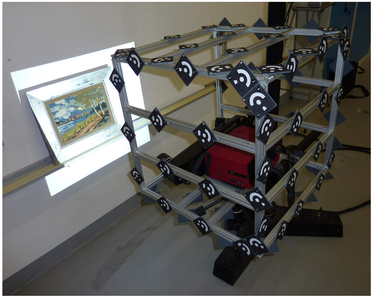
- CF, (OF, x⃗F, y⃗F, z⃗F) is the coordinate system linked to the target frame.
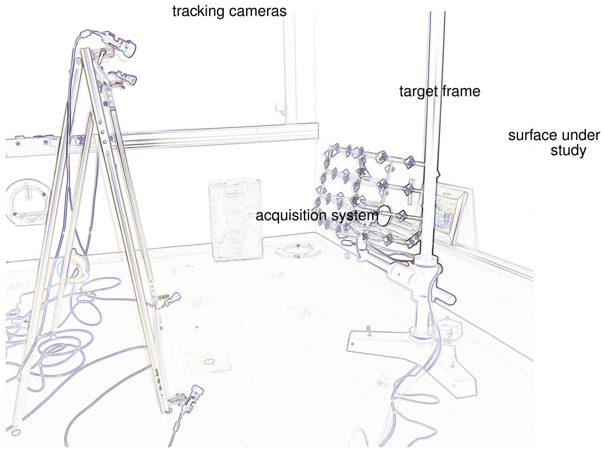
- CCj, (OCj, x⃗Cj, y⃗Cj, z⃗Cj) is the coordinate system linked to each tracking camera j. OCj is the optical center of the camera, (x⃗Cj, y⃗Cj) define the image plane, z⃗Cj is collinear to the optical axis.
- C0, (O0, x⃗0, y⃗0, Z⃗0) is the world coordinate system.
Calibration of the target frame
Calibration of the tracking cameras
Calibration of the acquisition system
Calibration between the target frame and the acquisition system
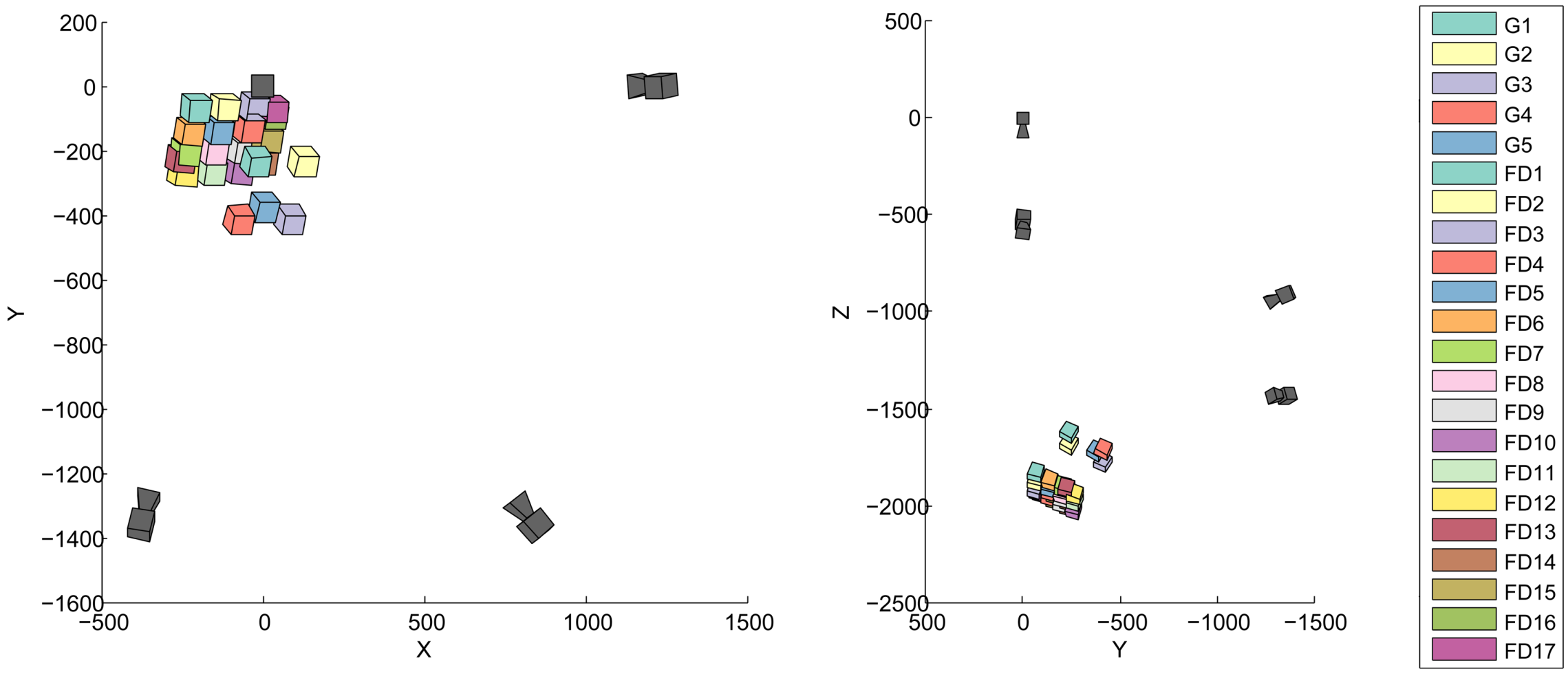
Orientation of the tracking cameras
- The interior and exterior orientation of the tracking cameras and the images of the target frame from the tracking cameras are used to compute the position and orientation of the target frame for each acquisition. This provides us with TC0,CF. We refer to this as tracking; this is what the simulations describe.
- Using the tracking results, the calibration between the tracking frame and the acquisition system, and the acquisition system calibration, we project the acquired data in a single coordinate system. We can thus calculate A∣C0, the coordinates of the surface points in the world system using:
2.2. Materials Used
2.2.1. Acquisition Systems
2.2.2. Tracking Material
2.2.3. Processing Software
2.3. Configuration Overview
3. Results and Discussion
3.1. Individual Calibrations
Sensor calibrations
Calibration of the target frame
Orientation of the tracking cameras
Orientation between the target frame and the acquisition systems
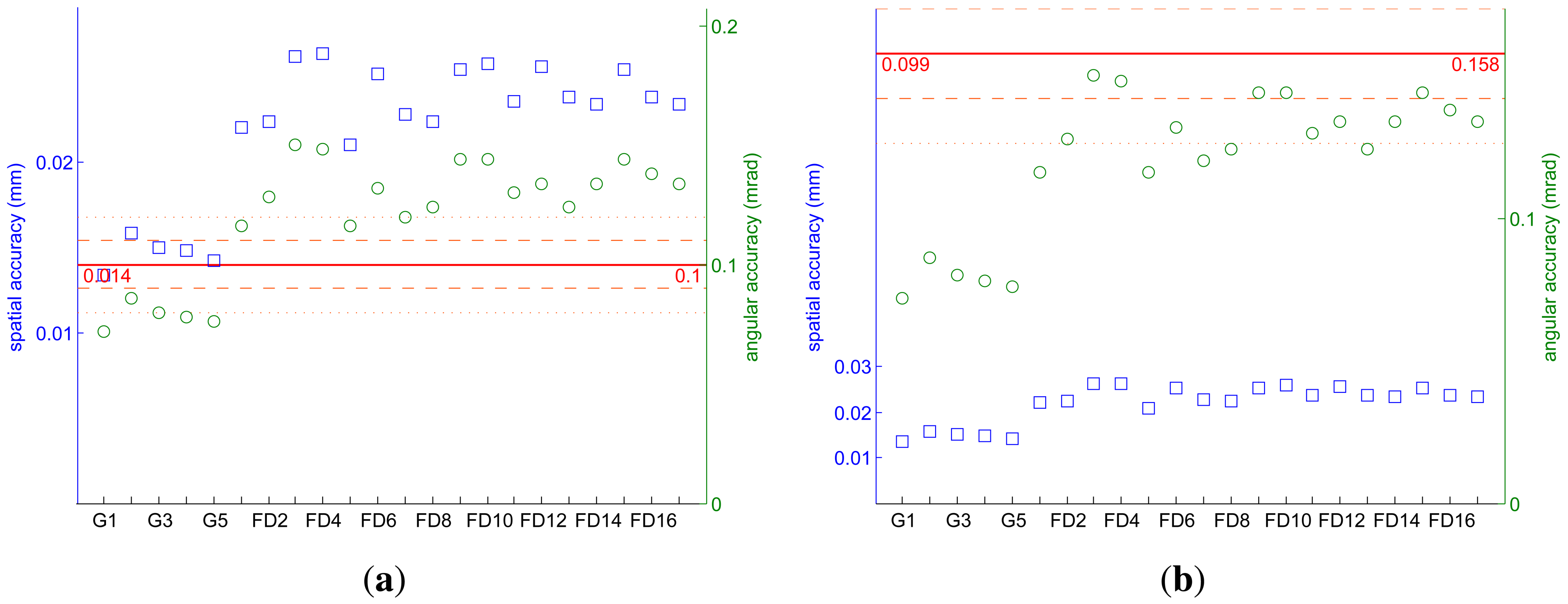
3.2. Tracking
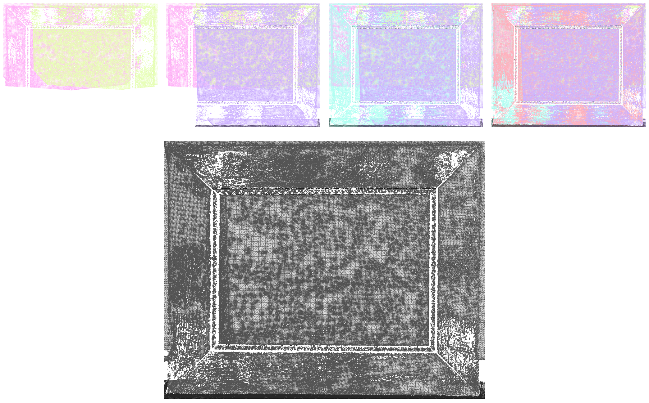
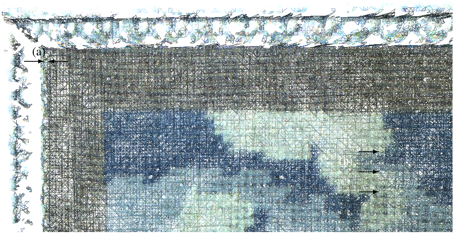
3.3. 3D Registration
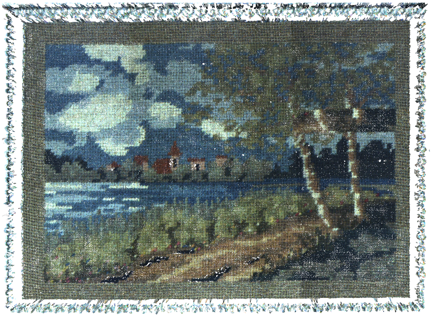
3.4. 3D / Multispectral Registration
4. Conclusions and Perspectives
Acknowledgments
References
- Pelagotti, A.; del Mastio, A.; de Rosa, A.; Piva, A. Multispectral imaging of paintings. IEEE Signal Process. Mag. 2008, 25, 27–36. [Google Scholar]
- Arnaoutoglou, F.; Koutsoudis, A.; Pavlidis, G.; Tsioukas, V.; Chamzas, C. Towards a Versatile Handheld 3D Laser Scanner. Proceedings of the 7th International Symposium on Virtual Reality, Archaeology and Cultural Heritage, Dresden, Germany, 25–27 September 2006.
- Tsirliganis, N.C.; Arnaoutoglou, F.; Koutsoudis, A.; Pavlidis, G.; Chamzas, C. 3D-archGIS: Archiving cultural heritage in a 3D multimedia space. DigiCult. Inform. 2003, 6, 6–10. [Google Scholar]
- Merritt, J.; Entwisle, D.; Monaghan, A. Integrated geoscience data, maps and 3D models for the City of Glasgow, UK. IAEG 2006, 394, 1–10. [Google Scholar]
- Serna, S.P.; Schmedt, H.; Ritz, M.; Stork, A. Interactive Semantic Enrichment of 3D Cultural Heritage Collections. Proceedings of the 13th International Symposium on Virtual Reality, Archaeology and Cultural Heritage, Brighton, UK, 19–21 November 2012.
- Mansouri, A.; Lathuiliere, A.; Marzani, F.; Voisin, Y.; Gouton, P. Toward a 3D multispectral scanner: An application to multimedia. IEEE MultiMed. 2007, 14, 40–47. [Google Scholar]
- Brusco, N.; Cortelazzo, G.M.; Capeleto, S.; Fedel, M.; Poletto, L.; Paviotti, A.; Tondello, G. A system for 3D modeling frescoed historical buildings with multispectral texture information. Mach. Vis. Appl. 2006, 17, 373–393. [Google Scholar]
- Tonsho, K.; Akao, Y.; Tsumura, N.; Miyake, Y. Development of gonio-photometric imaging system for recording reflectance spectra of 3D objects. Proc. SPIE 2001, 4663, 370–378. [Google Scholar]
- Sitnik, R.; Mczkowski, G.; Krzeslowski, J. Integrated shape, color, and reflectivity measurement method for 3D digitization of cultural heritage objects. Proc. SPIE 2010, 7526, 1–10. [Google Scholar]
- Bianco, G.; Bruno, F.; Tonazzini, A.; Salerno, E.; Savino, P.; Zitova, B.; Sroubek, F.; Console, E. A. Framework for Virtual Restoration of Ancient Documents by Combination of Multispectral and 3D Imaging; Puppo, E., Brogni, A., de Floriani, L., Eds.; Eurographics Italian Chapter Conference: Genova, Italy, 2010. [Google Scholar]
- Tsai, R. A versatile camera calibration technique for high-accuracy 3D machine vision metrology using off-the-shelf TV cameras and lenses. IEEE J. Robot. Autom. 1987, 3, 323–344. [Google Scholar]
- Pulli, K. Surface Reconstruction and Display from Range and Color Data. Ph.D. Thesis, University of Washington, Seattle, WA, USA, 1997. [Google Scholar]
- Rocchini, C.; Cignoni, P.; Montani, C.; Scopigno, R. Acquiring, stitching and blending diffuse appearance attributes on 3D models. Vis. Comput. 2002, 18, 186–204. [Google Scholar]
- Viola, P.; Wells, W.M.I. Alignment by maximization of mutual information. Int. J. Comput. Vis. 1997, 24, 137–154. [Google Scholar]
- Maes, F.; Collignon, A.; Vandermeulen, D.; Marchal, G.; Suetens, P. Multimodality image registration by maximization of mutual information. IEEE Trans. Med. Imag. 1997, 16, 187–198. [Google Scholar]
- Remondino, F.; Pelagotti, A.; Del Mastio, A.; Uccheddu, F. Novel Data Registration Techniques for Art Diagnostics and 3D Heritage Visualization. Proceedings of the 9th Conference on Optical 3D Measurement Techniques, Vienna, Austria, 1–3 July 2009.
- Palma, G.; Corsini, M.; Dellepiane, M.; Scopigno, R. Improving 2D-3D Registration by Mutual Information Using Gradient Maps; Puppo, E., Brogni, A., de Floriani, L., Eds.; Eurographics Italian Chapter Conference: Genova, Italy, 2010; pp. 89–94. [Google Scholar]
- Corsini, M.; Dellepiane, M.; Ponchio, F.; Scopigno, R. Image-to-geometry registration: A mutual information method exploiting illumination-related geometric properties. Comput. Graph. Forum 2009, 28, 1755–1764. [Google Scholar]
- Raab, F.H.; Blood, E.B.; Steiner, T.O.; Jones, H.R. Magnetic position and orientation tracking system. IEEE Trans. Aero. Electron. Syst. 1979, 15, 709–718. [Google Scholar]
- Paperno, E.; Sasada, I.; Leonovich, E. A new method for magnetic position and orientation tracking. IEEE Trans. Magn. 2001, 37, 1938–1940. [Google Scholar]
- Sherman, J.T.; Lubkert, J.K.; Popovic, R.S.; DiSilvestro, M.R. Characterization of a novel magnetic tracking system. IEEE Trans. Magn. 2007, 43, 2725–2727. [Google Scholar]
- Bernardini, F.; Rushmeier, H.; Martin, I.M.; Mittleman, J.; Taubin, G. Building a digital model of michelangelo's florentine pietà. IEEE Comput. Graph. Appl. 2002, 22, 59–67. [Google Scholar]
- Karaszewski, M.; Sitnik, R.; Bunsch, E. On-line, collision-free positioning of a scanner during fully automated three-dimensional measurement of cultural heritage objects. Robot. Autonom. Syst. 2012, 60, 1205–1219. [Google Scholar]
- Leica. T-Scan. Available online: http://metrology.leica-geosystems.com/en/Leica-T-Scan_1836.htm (accessed on 21 September 2012).
- Steinbichler. T-Scan 3. Available online: http://www.steinbichler.com/products/surface-scanning/3d-digitizing/t-scan-3.html (accessed on 21 September 2012).
- Creaform. MetraScan 70 and 120. Available online: http://www.creaform3d.com/en/metrology-solutions/optical-3d-scanner-metrascan (accessed on 21 September 2012).
- NDI. ScanTrak. Available online: http://www.ndigital.com/industrial/optotrakproseries-models.php (accessed on 21 September 2012).
- Blais, F.; Taylor, J.; Beraldin, J.A.; Godin, G.; Cournoyer, L.; Picard, M.; Borgeat, L.; Dicaire, L.; Rioux, M.; Lahanier, C.; Aitken, G. Ultra-high resolution imaging at 50Âţm using a portable XYZ-RGB color laser scanner. In International Workshop on Recording, Modeling and Visualization of Cultural Heritage; Taylor & Francis: Ascona, Switzerland, 2005. [Google Scholar]
- Luhmann, T. Close range photogrammetry for industrial applications. ISPRS J. Photogramm. Rem. Sens. 2010, 65, 558–569. [Google Scholar]
- Simon, C.; Schütze, R.; Boochs, F.; Marzani, F.S. Asserting the precise position of 3D and multispectral acquisition systems for multisensor registration applied to cultural heritage analysis. In Advances in Multimedia Modeling LNCS 7131; Schoeffmann, K., Merialdo, B., Hauptmann, A.G., Ngo, C.W., Andreopoulos, Y., Breiteneder, C., Eds.; Springer-Verlag: Heidelberg, Germany, 2012; pp. 597–608. [Google Scholar]
- FluxData. The FD-1665-MS 7 Channel Camera. Available online: http://www.fluxdata.com/products/fd-1665-ms7 (accessed on 18 October 2012).
- Berns, R.S.; Taplin, L.; Nezamabadi, M.; Mohammadi, M.; Zhao, Y. Spectral Imaging Using a Commercial Color-Filter Array Digital Camera. Proceedings of the 14th Triennial ICOM-CC Meeting, Citeseer, The Netherlands, 12–16 September 2005. Volume 2.
- Mansouri, A.; Marzani, F.S.; Gouton, P. Neural networks in two cascade algorithms for spectral reflectance reconstruction. IEEE Int. Conf. Image Process. 2005, 2, 718–721. [Google Scholar]
- Gom. ATOS-Industrial 3D Scanning Technology. Available online: http://www.gom.com/metrology-systems/3d-scanner.html (accessed on 6 October 2012).
- Gom. Tritop Deformation Software. Available online: http://www.gom.com/3d-software/tritop-deformation-software.html (accessed on 10 December 2012).
- Axios3D. Axori Photogrammetric Bundle Block Adjustment, AXOriLib 1.10.8. Available online: http://www.axios3d.de (accessed on 10 December 2012).
- Besl, P.J.; McKay, N.D. A method for registration of 3-D shapes. IEEE Trans. Pattern Anal. Mach. Intell. 1992, 14, 239–256. [Google Scholar]
- Rusinkiewicz, S.; Levoy, M. Efficient Variants of the ICP Algorithm. Proceedings of the 3rd International Conference on 3-D Digital Imaging and Modeling, Quebec, Canada, 28 May-1 June 2001; pp. 145–152.


| Characteristic | Value | Unit |
|---|---|---|
| Filtering technology | 3 CCD | |
| Number of spectral bands | 7 | |
| Sensor size (W × H) | 8.9 × 6.7 | mm × mm |
| 694 × 494 | pixels × pixels | |
| Cell size | 9.9 | μm |
| Focal length | 25 | mm |
| Acquisition range | 400–950 | nm |
| External dimensions | 92 × 112 × 187 | mm × mm×mm |
| Weight | 1.25 | kg |
| Acquisition system | Acquisition distance (mm) | Accuracy goal | |
|---|---|---|---|
| spatial (mm) | angular (mrad) | ||
| FluxData multispectral camera | 500 | 0.099 | 0.198 |
| Gom Atos III digitization system | 760 | 0.120 | 0.158 |
| Tracking cameras calibration |
| Multispectral camera calibration |
| Gom Atos III calibration |
| Target frame calibration |
| Tracking cameras orientation |
| Multispectral camera to target frame orientation |
| Multispectral acquisitions with simultaneous tracking |
| Gom Atos III to target frame orientation |
| Gom acquisitions with simultaneous tracking |
| Calibration | Measures | Simulations | Unit | |
|---|---|---|---|---|
| realistic | best | |||
| Tracking cameras calibration | 0.029 | 0.1 | 0.033 | pixel |
| Multispectral camera calibration | 0.035 | — | pixel | |
| Target frame calibration | 0.011 | 0.0 | 50 | mm |
| Tracking cameras orientation | 0.011 | 0.03 | 0.01 | mm |
| 0.014 | 0.04 | 0.02 | mrad | |
| Target frame to multispectral | 0.924 | — | mm | |
| camera orientation | 3.156 | — | mrad | |
| Target frame to Gom | 0.029 | — | mm | |
| Atos III orientation | 0.072 | — | mrad | |
© 2013 by the authors; licensee MDPI, Basel, Switzerland. This article is an open access article distributed under the terms and conditions of the Creative Commons Attribution license (http://creativecommons.org/licenses/by/3.0/).
Share and Cite
Chane, C.S.; Schütze, R.; Boochs, F.; Marzani, F.S. Registration of 3D and Multispectral Data for the Study of Cultural Heritage Surfaces. Sensors 2013, 13, 1004-1020. https://doi.org/10.3390/s130101004
Chane CS, Schütze R, Boochs F, Marzani FS. Registration of 3D and Multispectral Data for the Study of Cultural Heritage Surfaces. Sensors. 2013; 13(1):1004-1020. https://doi.org/10.3390/s130101004
Chicago/Turabian StyleChane, Camille Simon, Rainer Schütze, Frank Boochs, and Franck S. Marzani. 2013. "Registration of 3D and Multispectral Data for the Study of Cultural Heritage Surfaces" Sensors 13, no. 1: 1004-1020. https://doi.org/10.3390/s130101004