Hardware Implementation of Lorenz Circuit Systems for Secure Chaotic Communication Applications

Abstract
: This paper presents the synchronization between the master and slave Lorenz chaotic systems by slide mode controller (SMC)-based technique. A proportional-integral (PI) switching surface is proposed to simplify the task of assigning the performance of the closed-loop error system in sliding mode. Then, extending the concept of equivalent control and using some basic electronic components, a secure communication system is constructed. Experimental results show the feasibility of synchronizing two Lorenz circuits via the proposed SMC.1. Introduction
Chaos theory is a branch of nonlinear system theory and has been intensively studied in the past four decades. In 1963, E. N. Lorenz presented the first well-known chaotic system, which was a third-order autonomous system with only two multiplication-type quadratic terms but which displayed very complex dynamic behaviors [1]. The control problems of chaos phonemes have been extensively studied over the past two decades based on its particular properties, such as broadband noise-like waveforms, difficult predictability, and sensitivity to initial condition variations, etc. Until now, many control methods under the assumptions of knowing the structure of nonlinearity or matching condition, have been extensively considered for the subject of chaos synchronization [2–8].
Recently, the chaos synchronization between master (transmitter) and slave (receiver) chaotic systems has been an attractive topic for its potential applications in secure communication [9–13]. Several control schemes have been developed for the synchronization of chaotic systems. Sliding mode control is a characteristic kind of variable structure system which has been a useful and distinctive robust control strategy for many kinds of engineering systems in these past two decades. By designing a switching surface and using a discontinuous control law, the trajectories of dynamic systems can be forced to slide along the fixed sliding manifold. The sliding mode control technique has been successfully applied to synchronization of chaotic system [5,6,11]. Work [14] proposed a proportional-integral (PI) control scheme based on SMC technique-based to solve the synchronization problem of unified chaotic systems. The proposed PI controller is used to guarantee the synchronization between the transmitter and the receiver in secure communication systems.
To verify the above systems performance, in this paper a SMC-based chaotic secure communication system, which includes two chaotic Lorenz circuits (transmitter and receiver) and a sliding mode controller, is realized by using some electronic components containing operational amplifiers (OPAs), resistors and capacitors.
2. Problem Formulation and Main Results
The aim of this paper was to utilize the unpredictable characteristics of chaos signals, such as broadband noise-like waveform, prediction difficulty and sensitivity to initial condition variations, to construct a secure communication system. Now we consider the following Lorenz circuits, which are typical chaotic systems that have been thoroughly studied [14].
Master Lorenz chaotic circuit:
Slave Lorenz chaotic circuit:
Obviously, Equations (1) and (2) becomes the original Lorenz system for α = 0, where ẋm and ẋs denote the derivative of xm and xs with respect to time t, u(t) is the controller output used to synchronize the master and slave systems Equations (1) and (2), and p(t) is the embedded message bounded by:
The control goal is for the two Lorenz chaotic systems Equations (1) and (2) to be synchronized such that the resulting error vector satisfies:
The error vectors and error dynamics are defined as:
Then, the following error dynamics are obtained:
To stabilize the error dynamics Equations (7) and achieve synchronization, two basic steps are used: first, an appropriate switching surface is selected such that the sliding motion on the sliding manifold is stable and ensures limt→∞ ‖e(t)‖ = 0; second, a SMC law which guarantees the existence of the sliding mode s(t) = 0 is established. To guarantee the asymptotic stability of the sliding mode, the PI switching surface s(t) is defined as:
Having established the appropriate switching surface Equations (8), as described above, the next step is to design a SMC scheme to drive the system trajectories onto the sliding mode s(t) = 0. This study proposes the following SMC:
After design the control to ensure limt→∞ ‖E(t)‖ = limt→∞ ‖[1(t) e2(t) e3 (t)]‖ = 0. We have the following fact:
Then, we can infer that:
3. Experimental Results
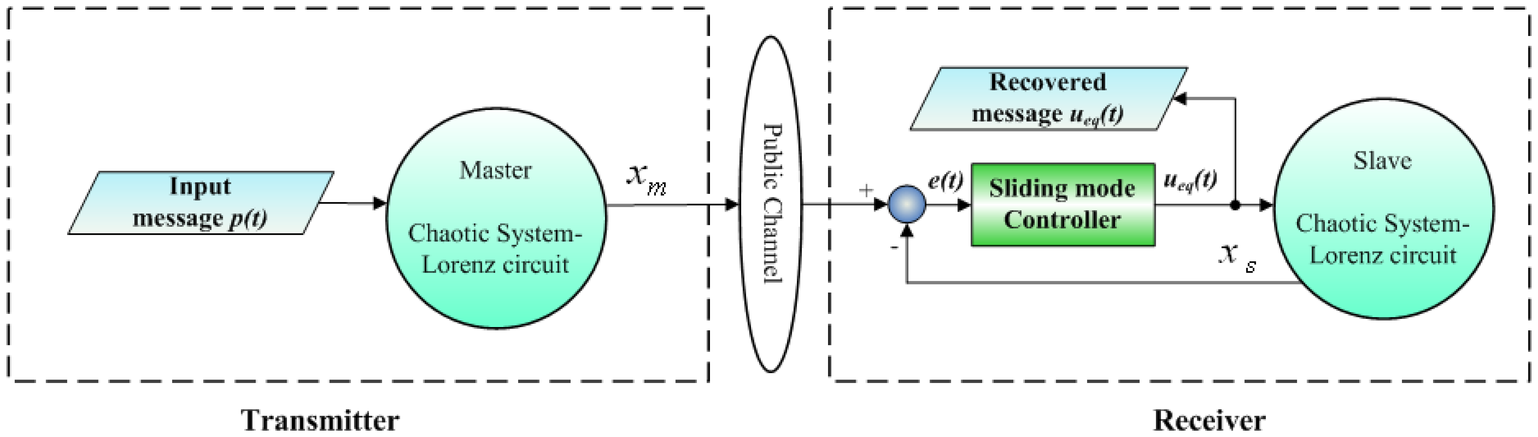
The preceding SMC scheme of synchronization is applied to establish chaotic secure communication systems. Figure 1 illustrates the proposed communication system that consists of a transmitter and a receiver [aster and slave Lorenz circuits (for α = 0), respectively]. The input message p(t) is embedded into the chaotic transmitter and the state of the master Lorenz system is simultaneously transmitted to the receiver. The equivalent SMC synchronization scheme of Equation (12) is given in the receiver. From the discussion in the section above, it ensures that the input message p(t) can be completely recovered on the receiver side using the equivalent controller Equation (12), if the synchronization between the transmitter and the receiver can be achieved.
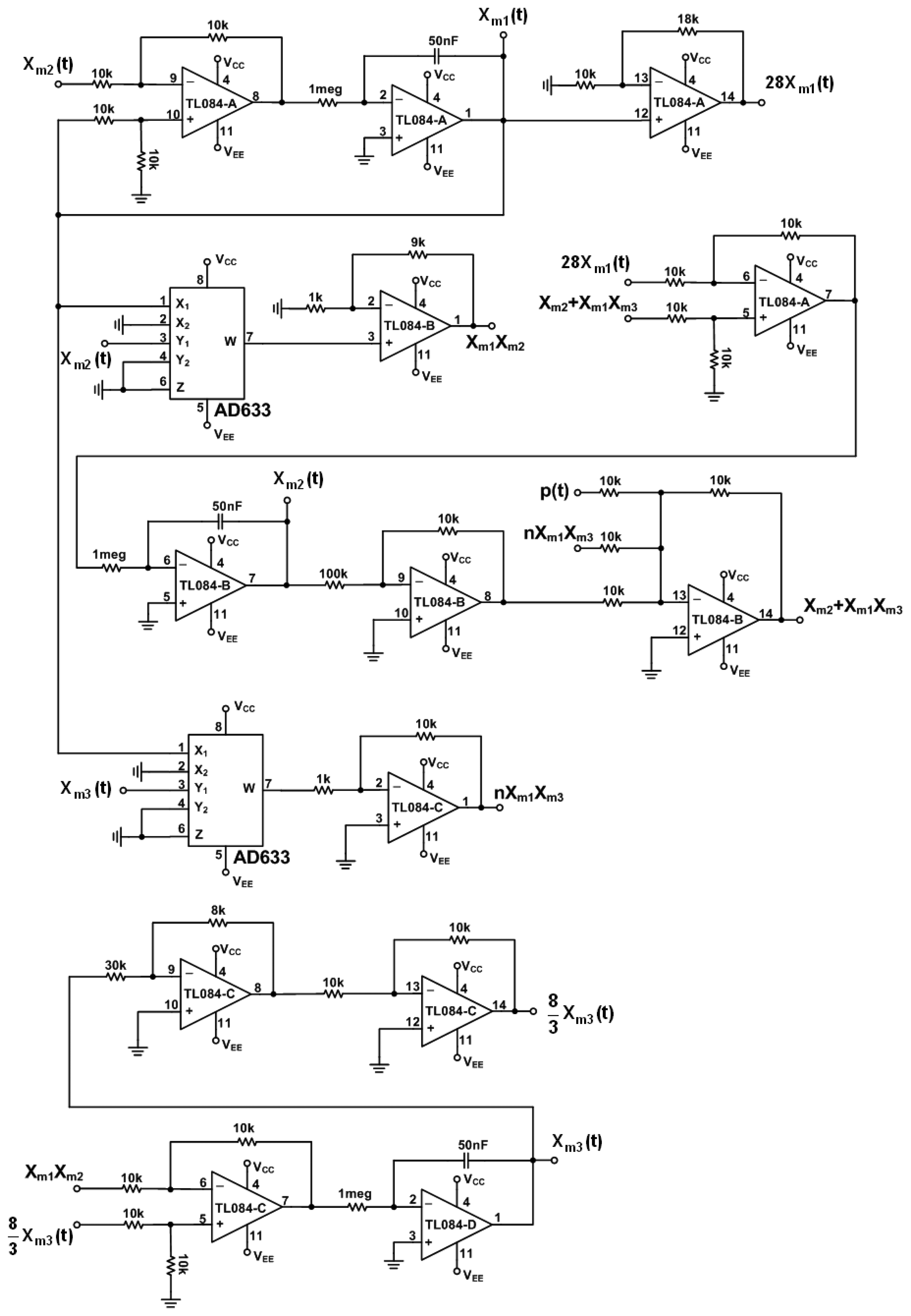
In the following, we use simple electronic components: OPAs, resistors and capacitors to implement the presented secure communication system. In order to speed up the dynamic response of chaotic Lorenz circuit, we rescale the systems Equations (1) and (2) by a new time scale , and then we have the following systems, respectively:
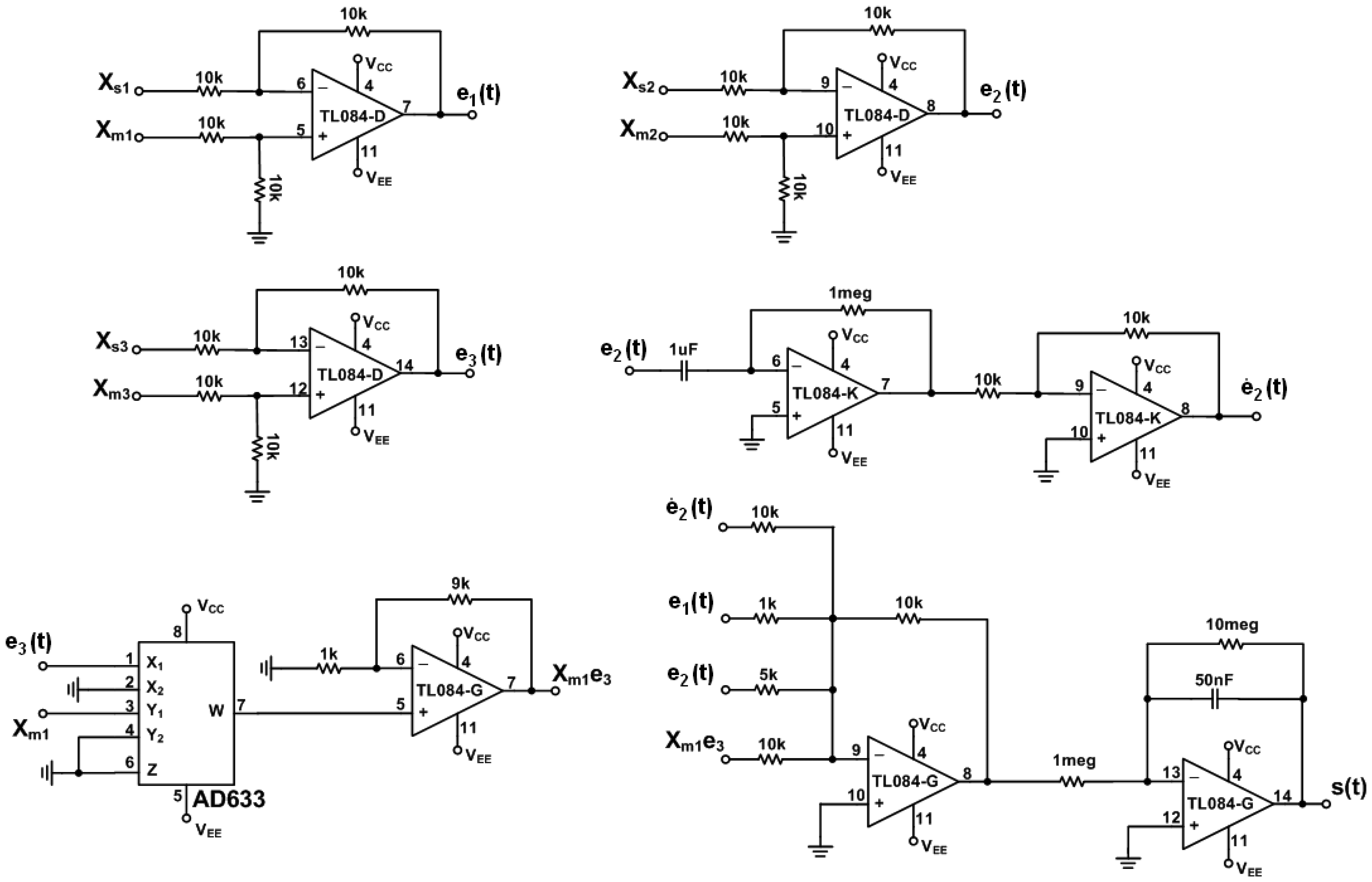
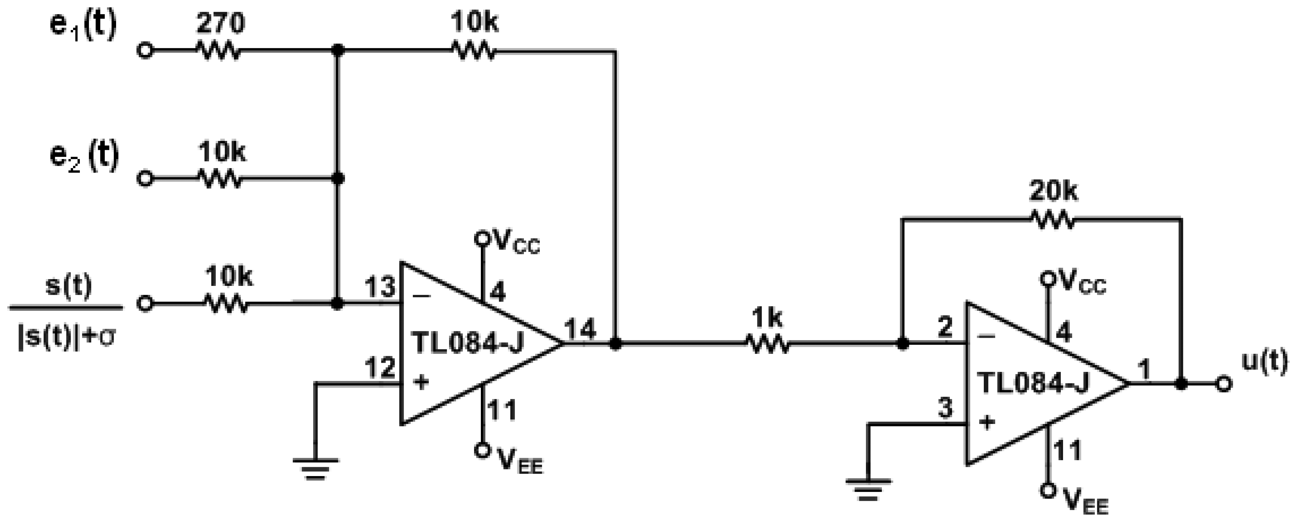
The circuit of error dynamics e(t) and the switch surface s(t) circuit are shown in Figure 4. The circuits of the continuous equivalent control ueq(t) Equations (12) is shown in Figures 5 and 6. In order to demonstrate the chaotic secure communication, the embedded message p(t) is specified as a sine wave (1 V, 5 Hz) in the transmitter.
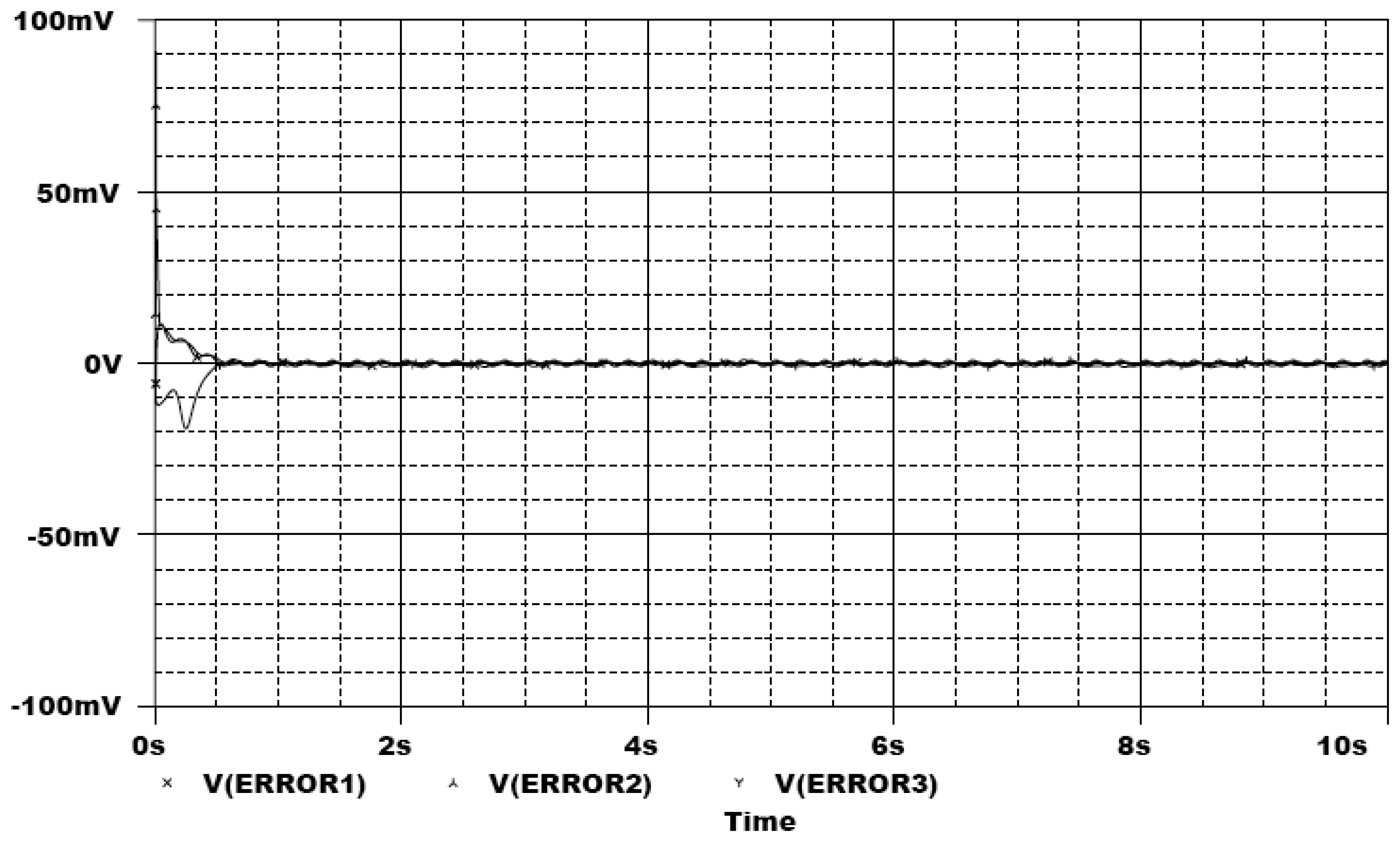
In the following, the commercial electronic circuit simulation software Orcad/PSpice 9.0 is used. Figure 7 shows the trajectories of the Lorenz system. Figure 8 shows the experimental results of synchronization between state xm and state xs. Figure 9 shows the experimental results of errors between state xm and state xs. Figure 10 shows the experimental result of switch surface s(t). From these figures, we can observe that the switching surface s(t) approaches zero within 0.5 s and the synchronization errors approach zero after 0.5 s, and then both the master and slave are synchronous. Figure 11 shows the experimental results of the continuous equivalent control ueq(t) and input message p(t). From this figure, we can observe that the input message p(t) (sine wave: 1 V, 5 Hz) can be successful recovered.
4. Conclusions
This study has been proposed to ensure the synchronization between the master and the controlled slave Lorenz chaotic systems via a sliding mode controller. Furthermore, the proposed scheme has been also successfully applied to a secure communication system. Some basic electronic circuits are used to implement the SMC-based secure communication system. The experimental results verify that the methods are correct and practical.
Acknowledgments
The authors thank the National Science Council of Taiwan for supporting this work under grants NSC 101-2622-E-269-012-CC3 and NSC 101-2221-E-241-002. The authors also wish to thank the anonymous reviewers for providing constructive suggestions.
References
- Lorenz, E.N. Deterministic non-periodic flows. J. Atmos. Sci. 1963, 20, 130–141. [Google Scholar]
- Pecora, L.M.; Carroll, T.L. Synchronization in chaotic systems. Phys. Rev. Lett. 1990, 64, 821–824. [Google Scholar]
- Huang, C.K.; Tsay, S.C.; Wu, Y.R. Implementation of chaotic secure communication systems based on OPA circuits. Chaos Solitons Fractals 2005, 23, 589–600. [Google Scholar]
- Alvarez, G.; Hernández, L.; Muñoz, J.; Montoya, F.; Li, S.J. Security analysis of communication system based on the synchronization of different order chaotic systems. Phys. Lett. A. 2005, 345, 245–250. [Google Scholar]
- Yau, H.T.; Kuo, C.L.; Yan, J.J. Fuzzy sliding mode control for a class of chaos synchronization with uncertainties. Int. J. Nonlin. Sci. Num. Simul. 2006, 7, 333–338. [Google Scholar]
- Martinez-Guerra, R.; Yu, W. Chaotic synchronization and secure communication via sliding-mode observer. Int. J. Bifurcat. Chaos. 2008, 18, 235–243. [Google Scholar]
- Hu, M.; Xu, Z. Adaptive feedback controller for projective synchronization. Nonlin. Anal. Real World Appl. 2008, 9, 1253–1260. [Google Scholar]
- Liao, T.L.; Tsai, S.H. Adaptive synchronization of chaotic systems and its application to secure communications. Chaos Solitons Fractals 2000, 11, 1387–1396. [Google Scholar]
- Li, Z.; Li, K.; Wen, C.; Soh, Y.C. A new chaotic secure communication system. IEEE Trans. Commun. 2003, 51, 1306–1312. [Google Scholar]
- Li, Z.; Xu, D. A secure communication scheme using projective chaos synchronization. Chaos Solitons Fractals 2004, 477–481. [Google Scholar]
- Almeida, D.I.R.; Alvarez, J.; Barajas, J.G. Robust synchronization of Sprott circuits using sliding mode control. Chaos Solitons Fractals 2006, 30, 11–18. [Google Scholar]
- Zhou, J.; Huang, H.B.; Qi, G.X.; Yang, P.; Xie, X. Communication with spatial periodic chaos synchronization. Phys. Lett. A. 2005, 335, 191–196. [Google Scholar]
- Wen, G.; Wang, Q.G.; Lin, C.; Han, X.; Li, G. Synthesis for robust synchronization of chaotic systems under output feedback control with multiple random delays. Chaos Solitons Fractals 2006, 29, 1142–1146. [Google Scholar]
- Hou, Y.Y.; Liau, B.Y.; Chen, H.C. Synchronization of unified chaotic systems using sliding mode controller. Math. Probl. Eng. 2012. [Google Scholar] [CrossRef]
- Tan, C.P.; Edwards, C. Sliding mode observers for detection and reconstruction of sensor faults. Automatica 2002, 38, 1815–1821. [Google Scholar]
- Edwards, C.; Spurgeon, S.K.; Patton, R.J. Sliding mode observers for fault detection and isolation. Automatica 2000, 36, 541–548. [Google Scholar]


© 2013 by the authors; licensee MDPI, Basel, Switzerland. This article is an open access article distributed under the terms and conditions of the Creative Commons Attribution license (http://creativecommons.org/licenses/by/3.0/).
Share and Cite
Chen, H.-C.; Liau, B.-Y.; Hou, Y.-Y. Hardware Implementation of Lorenz Circuit Systems for Secure Chaotic Communication Applications. Sensors 2013, 13, 2494-2505. https://doi.org/10.3390/s130202494
Chen H-C, Liau B-Y, Hou Y-Y. Hardware Implementation of Lorenz Circuit Systems for Secure Chaotic Communication Applications. Sensors. 2013; 13(2):2494-2505. https://doi.org/10.3390/s130202494
Chicago/Turabian StyleChen, Hsin-Chieh, Ben-Yi Liau, and Yi-You Hou. 2013. "Hardware Implementation of Lorenz Circuit Systems for Secure Chaotic Communication Applications" Sensors 13, no. 2: 2494-2505. https://doi.org/10.3390/s130202494