Attitude Heading Reference System Using MEMS Inertial Sensors with Dual-Axis Rotation

Abstract
: This paper proposes a low cost and small size attitude and heading reference system based on MEMS inertial sensors. A dual-axis rotation structure with a proper rotary scheme according to the design principles is applied in the system to compensate for the attitude and heading drift caused by the large gyroscope biases. An optimization algorithm is applied to compensate for the installation angle error between the body frame and the rotation table's frame. Simulations and experiments are carried out to evaluate the performance of the AHRS. The results show that the proper rotation could significantly reduce the attitude and heading drifts. Moreover, the new AHRS is not affected by magnetic interference. After the rotation, the attitude and heading are almost just oscillating in a range. The attitude error is about 3° and the heading error is less than 3° which are at least 5 times better than the non-rotation condition.1. Introduction
Attitude heading reference systems (AHRSs) which provide in-motion horizontal attitude as pitch and roll, and vertical angle as heading, are widely used in Autonomous Underwater Vehicles (AUVs) [1,2]. In order to afford sufficiently high precision, an AHRS often requires an inertial measurement unit (IMU) with high accuracy optical gyroscopes and quartz flexible accelerometers. It is too expensive to the low-cost applications. Moreover, the size of the AHRS is large. It does not fit the small sized and low cost AUVs such as the followers of a multi AUVs cooperative navigation system [3]. The position of the followers could be obtained from the leaders, while the attitude and heading should be gathered by itself. A thrifty way of doing this is using a digital magnetic compass [4,5]. These devices are low-cost and could achieve a heading accuracy of several milliradians. However, the accuracy drops easily while encountering electromagnetic interference such as the motors and the solenoid for the emergency jettison in the AUVs. It is not robust in such a harsh environment. With the fast development of low-cost Micro-Electro-Mechanical System (MEMS), the AHRS with MEMS inertial sensors could be a potential method.
Nowadays, the bias instability of the commercial MEMS gyroscopes is about several or more than 10°/h [6,7]. It is not enough for an AHRS, but the output accuracy could be improved by the IMU rotation technology [8,9]. The IMU rotation technology was initiated by the North Atlantic Treaty Organization (NATO) in the 1980s for marine inertial navigation systems [10]. This technology includes two main types, the single-axis rotation type such as MK39 and WSN-7B [11] and the dual-axis rotation type such as MK49 and WSN-7A [12,13]. It could reduce part of the inertial sensors' drifts for the single-axis rotation type; while the drifts of all the inertial sensors could be removed for the dual-axis type. Recently, this technology is still developing. The rotation scheme would affect the compensation result. Yuan et al. proposed an 8-sequence and a 16-sequence rotation scheme for the dual-axis rotational INS, which could compensate not only the drifts but also the scale factor errors of the gyroscopes [10]. The mounting errors between the IMU's body frame and the rotation table's frame must be calibrated since these errors will significantly affect the output attitude. Song et al. introduced the thin-shell algorithm to alignment these errors [14].
In recent times, this technology has been extended to the MEMS inertial sensors fields. Iozan et al. designed a north finding system using a MEMS gyroscope with a single-axis rotary table to compensate the gyroscope's bias [15]. Wei et al. introduced a MEMS gyroscope north finding system for mobile robot with a single-axis turntable [16]. It could detect the heading angle while the robot is stationary. Renkoski proposed a dual-axis continues rotation MEMS IMU for gyrocompassing applications. With a baseball stitch like slew, the heading angle error was almost not increasing in 60 s, and the north finding accuracy is improved compared with the 2-postion method [17].
This paper introduces IMU rotation technology into MEMS inertial sensors to produce an AHRS. The AHRS is self-contained and could provide in-motion horizontal attitude and heading. The rest paper is organized as follows. Section 2 explains the problem in mathematics. Section 3 proposes the AHRS and its rotary scheme according to the design principles. Section 4 analyzes the error sources of the AHRS and demonstrates the error compensation scheme in mathematics. The accuracy of the AHRS is evaluated with simulation in Section 5 and experiments in Section 6. Conclusions are drawn in Section 7.
2. Problem Statement
The coordinate frames used here are defined as follows:
The n frame is the ideal local level navigation coordinate frame with east-north-up geodetic axes.
The n′ frame is the real local level navigation coordinate frame. There are some errors between n and n′ frame owing to the sensor errors.
The b frame is the MEMS inertial sensor's body coordinate frame.
The e frame is the Earth coordinate frame.
The i frame is the nonrotating inertial coordinate frame.
The r frame is the rotation table's frame.
The d frame is the vehicle's body coordinate frame.
The attitude and heading are updated using the common navigation equation as [18]
Owing to the gyroscopes' measurement errors, the true is unavailable. In most case, we could only obtain its approximation with some errors as . The Euler angle errors between the n frame and the n′ frame are described as [19–21]
For an accurate AHRS, the goal is to make every effort to let close to the true DCM . In other words, let α close to zero.When α is close to zero, for Equation (3), the part is near zero. Because the AUVs would not sail in a very high speed (commonly several meters per second), the part is only several percent °/h if we regard the velocity as zero. Also, the part is several percent °/h if the latitude is roughly known, while the MEMS gyroscopes' error is several or more than 10°/h. In order to let α close to zero, the key is to make every effort to reduce the effect caused by the gyroscopes' biases, scale factor errors, and the axis misalignment errors.
3. Design Principles
Equation (7) can be separated with two parts: and . For the first part, is frequently changing through two axis rotations. Therefore, if the sum of could reach zero, the first part could be compensated. While with the introduction of the additional rotations, would be much larger. This means that the second part would be increased. So the design principles should be as follows:
Try to keep .
The rotation should be performed in both directions to compensate the part.
The rotational speed should be fast to ensure that the gyroscopes' biases and scale factor errors are as unchanged in one compensation cycle.
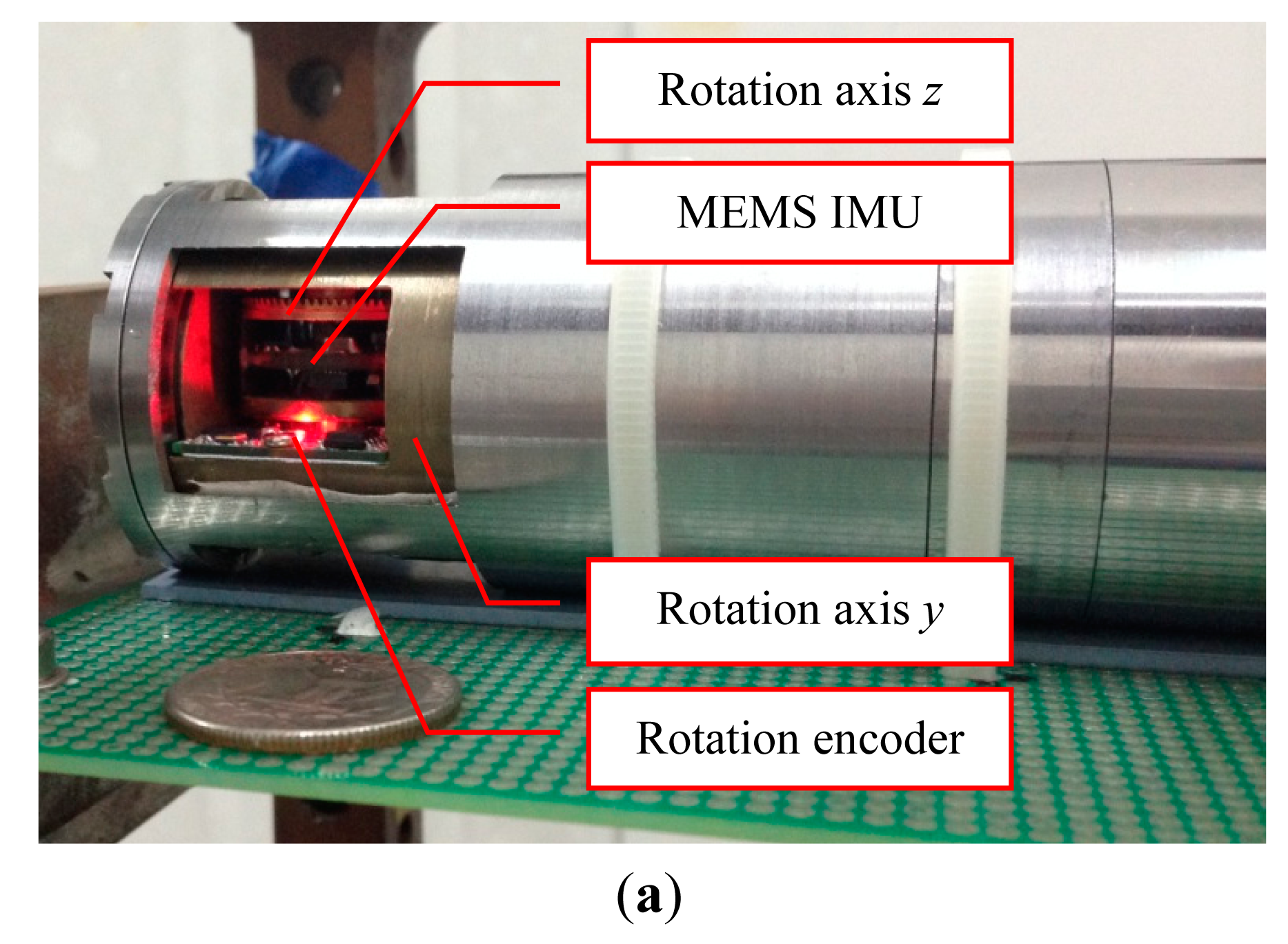
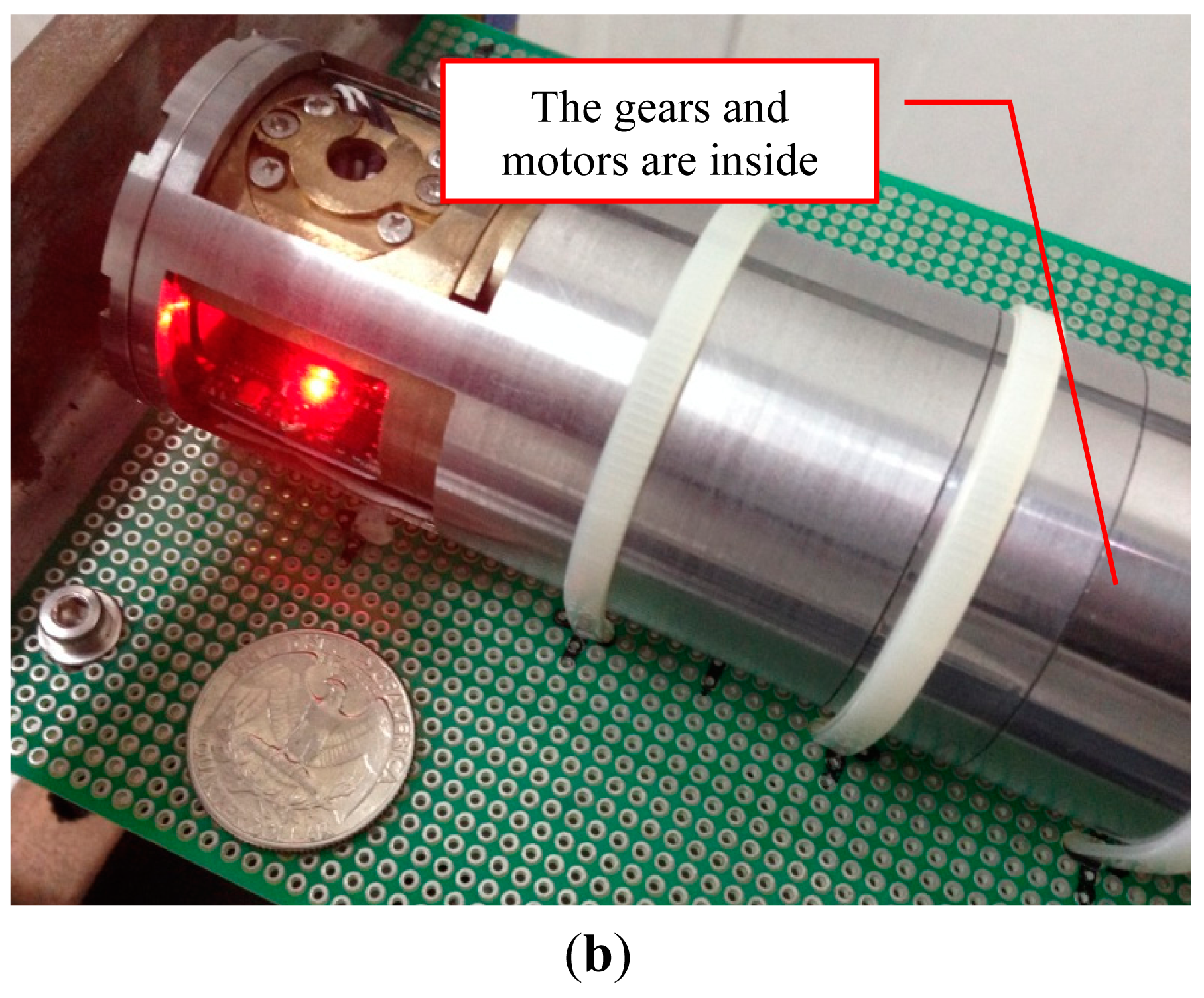
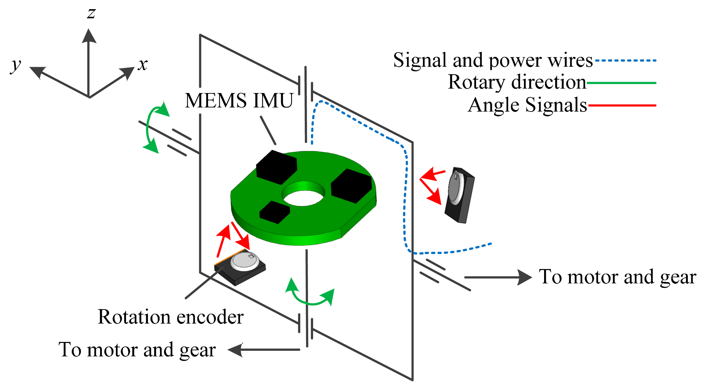
In view of these principles, a MEMS inertial sensor based AHRS is designed as shown in Figure 1. The block diagram is shown in Figure 2.
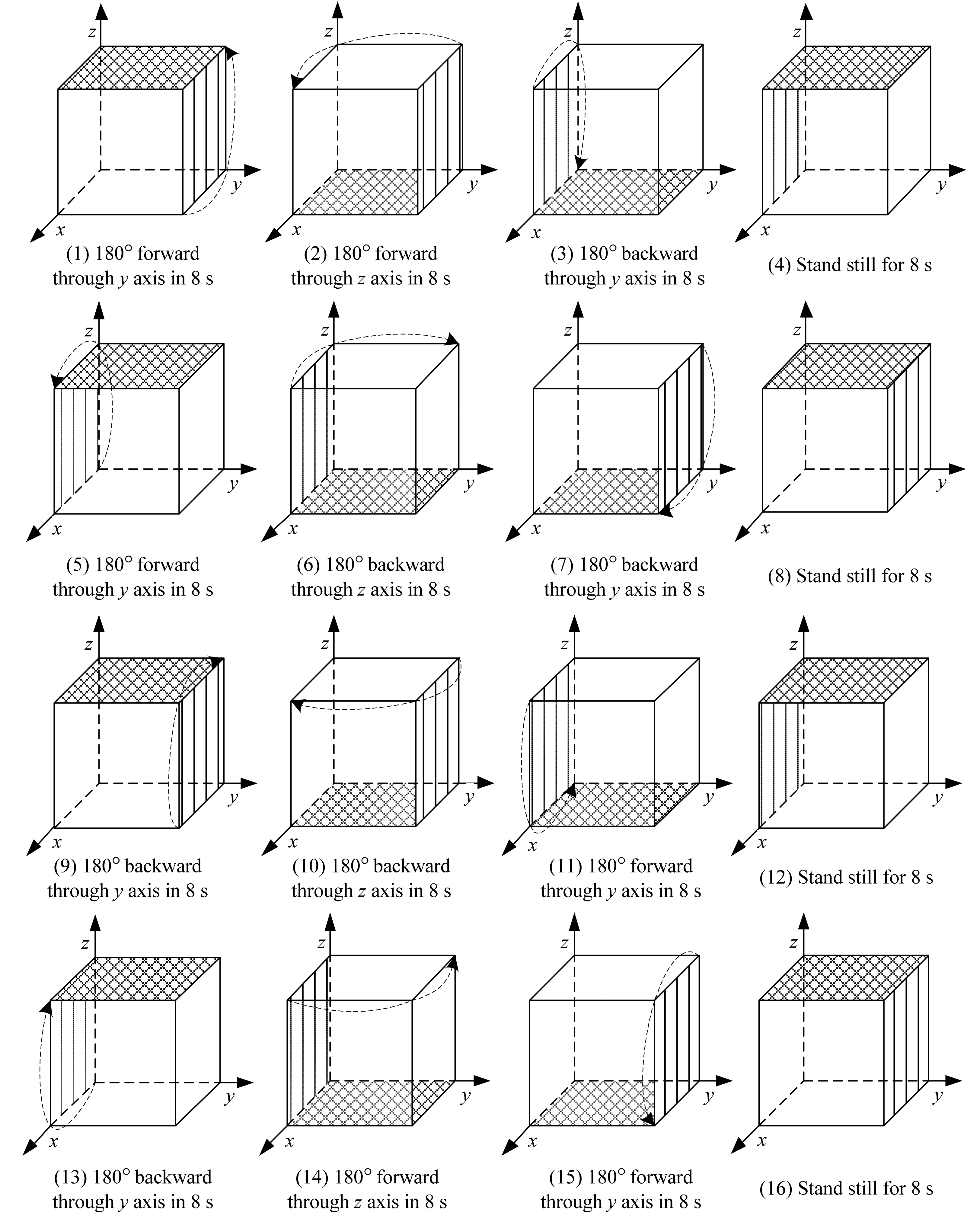
The AHRS is designed as a y-z two axis reversible rotational structure. The rotation encoders are installed in both directions to measure the rotational angles since these extra angles should be compensated while outputting the attitude and heading. The signal and power wires are through the rotary centers to avoid the length changes. According to the rotational structure, a proper rotary scheme is considered, as presented in Figure 3.
Firstly, the rotation is performed in back and forth mode to avoid the influence of scale factor errors and axis misalignment errors and to keep the wires untwined. Secondly, since there are acceleration and deceleration stages for any rotation, the rotation is divided into 180° for one step. Then the duration of each direction and its opposite direction could be the same. Thirdly, 8 s is the fastest time that the motor and gear could finish the 180° turn.
4. Error Analysis and Compensation for the AHRS
In this section, we will have a delicate numerical analysis of the AHRS's attitude and heading errors according to the rotary scheme designed in Section 3. Besides, a new compensation algorithm to deal with the installation errors between the b frame and the r frame is proposed.
4.1. Installation Error Compensation
For a general AHRS, the outputs are the IMU's attitude and heading. While for a rotational AHRS, the additional information caused by the rotation should be compensated. The attitude and heading should be included in the DCM between the d frame and the n frame as
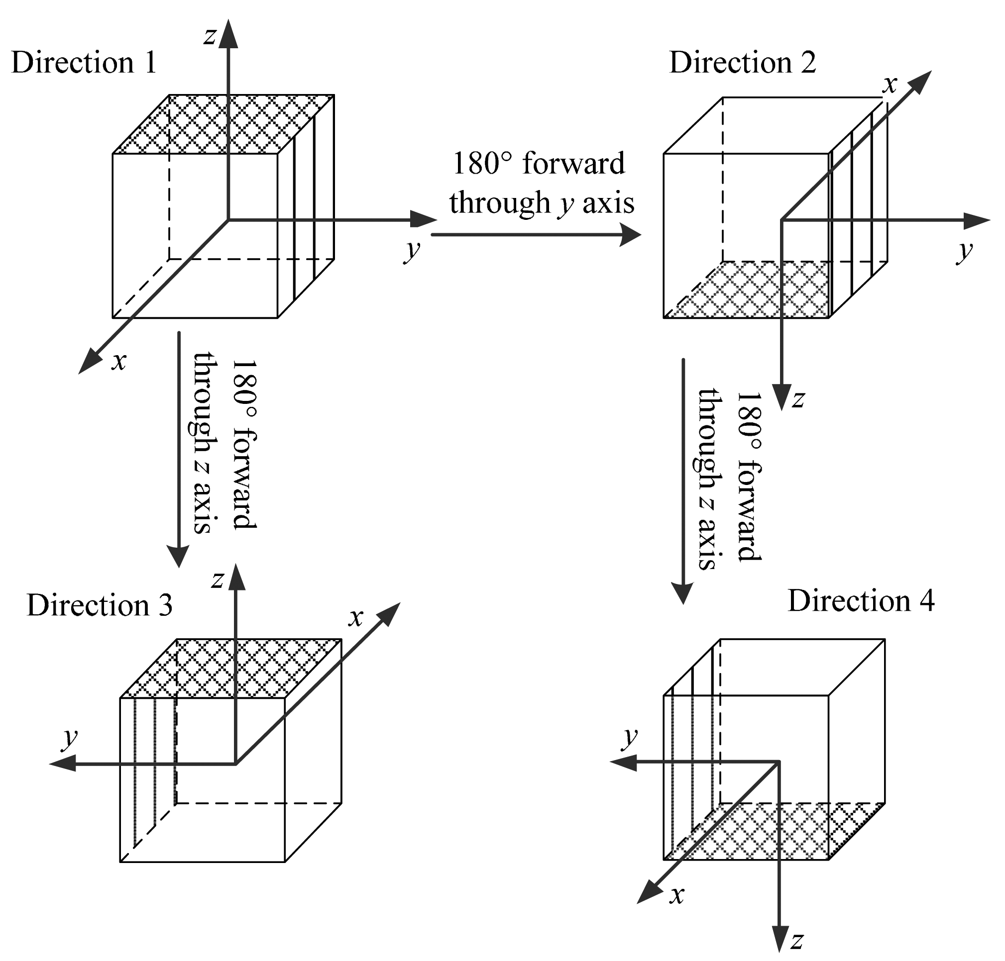
Here, an optimization method is presented to detect the installation error DCM . The rotary structure is rotated into four directions, displayed in Figure 4. The specific force of the IMU is collected as , m = 1,2,3,4. There exists a relationship between f b and f r as
For the equation like Equation (9), if f r is known, can be uniquely solved by an optimization method using the singular value decomposition (SVD) as [22]
- Step 1:
Calculate the 3 × 3 matrix
- Step 2:
Determine the SVD of H
- Step 3:
Calculate
So the key is to identify f r. From Equations (9) and (10), we could get some interesting relations as
And the signs of fr can be determined by making the r frame oblique in direction 1.
4.2. Attitude and Heading Errors Compensation
This part gives the numerical analysis of the attitude and heading errors based on the proposed rotary scheme to explain how this scheme can achieve the effect described in Equation (7).
There are acceleration and deceleration stages in each rotational step. The sinusoids are used here to simulate the rotational speed as
Then, the rotation steps from 1 to 16 can be expressed as
- Step 1
- Step 2
- Step 3
- Step 4
- Step 5
- Step 6
- Step 7
- Step 8
- Step 9
- Step 10
- Step 11
- Step 12
- Step 13
- Step 14
- Step 15
- Step 16
From Equation (8), can be conveyed as
And then the error compensation of the rotary scheme in each cycle can be obtained as follows
Equations (35) and (36) show that the proposed rotary scheme could achieve the goal in Equation (7). The biases, scale factor errors, and axis misalignment errors can be completely counteracted.
5. Simulation
Three simulations are carried out to verify the rotation schemes. The conditions for the simulation are as follows: (1) the simulation's latitude is 30°; (2) the rotation time for each step is 8 s; (3) the simulation time is 3600 s.
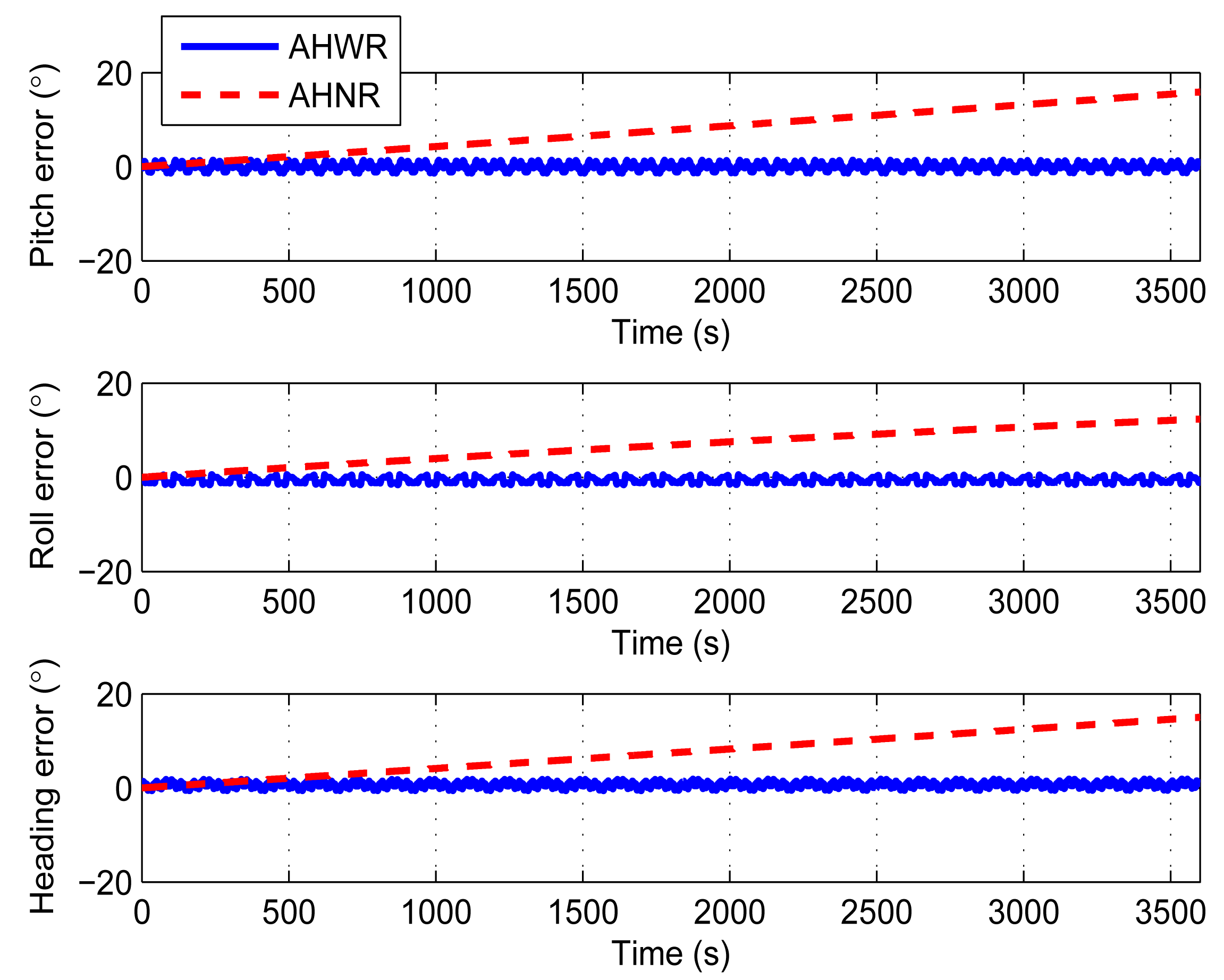
The derivation in Sections 3 and 4 is based on the principle that the sensor errors are as unchanged in one compensation cycle. So, constant errors are applied in the first simulation to prove that the derivation is reasonable. The constant biases are set to 15°/h; the constant scale factor errors are set to 0.2% of the scale factor; and the constant axis misalignment angles are set to 0.6° for the simulation. The simulation also includes a comparison between two methods: (1) attitude and heading sensing with rotations (AHWR); (2) attitude and heading sensing without rotations (AHNR). Figure 5 and Table 1 show the comparison results. The attitude and heading errors are significantly decreased based on the rotation scheme. The errors do not increase with time compared with AHNR.
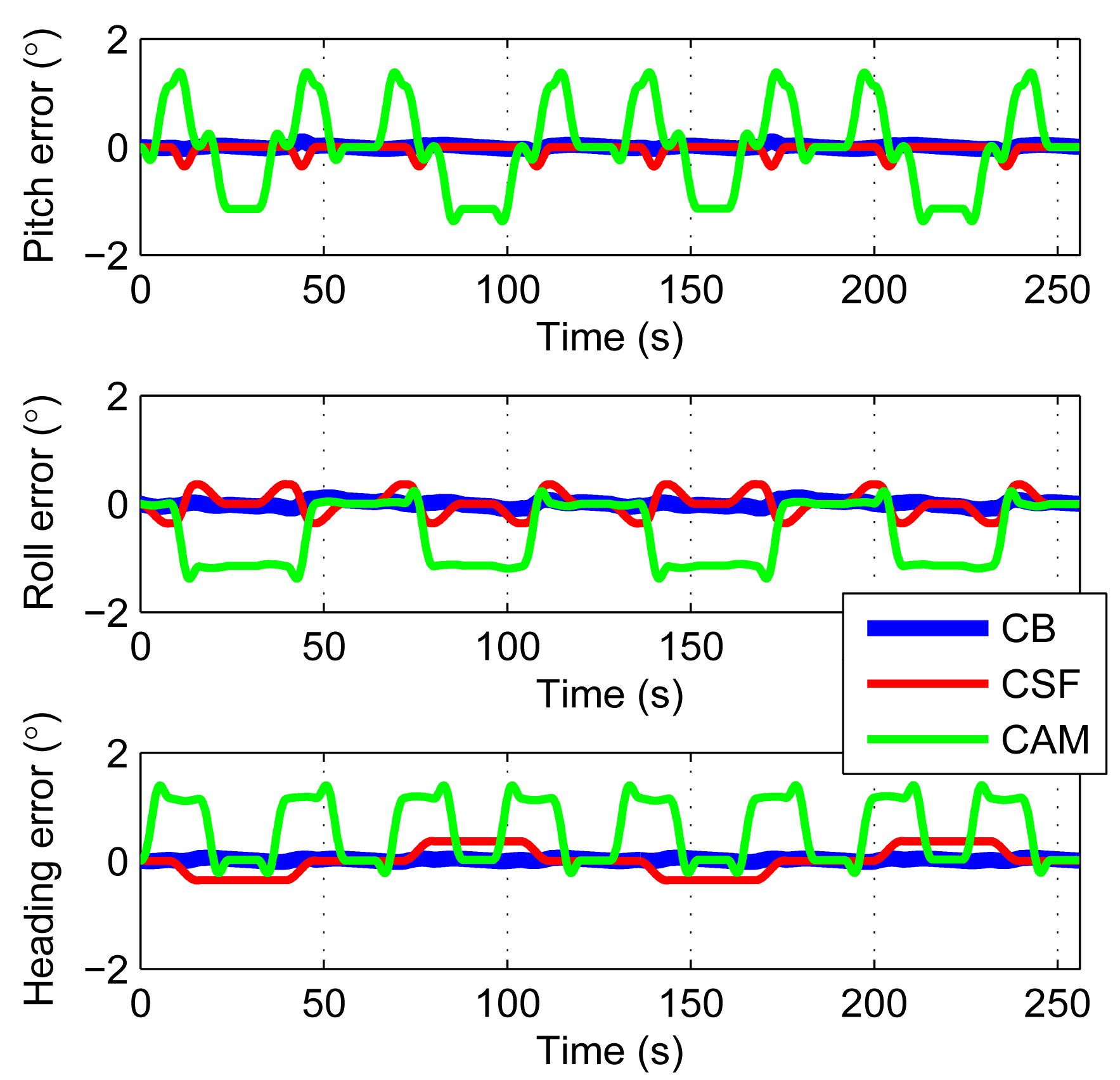
In order to separate the errors, the simulation also includes AHWR with constant gyro bias only (CB), AHWR with constant gyro scale factor errors only (CSF), and AHWR with constant axis misalignment angles only (CAM). Figure 6 shows the results within 2 compensation cycles. One compensation cycle lasts 128 s.The errors caused by gyroscope bias may increase in quarter of a cycle. So, it equals to 0.14° with gyroscope bias of 15°/h. The residual errors caused by the scale factor errors are about 0.4° and the remaining errors caused by the axis misalignment angles are about 1.5° when rotating 180°. They are all consistent with the error sources. Owing to the back and forth rotary scheme, the errors are only oscillating. Note also that the error levels of CSF and CAM are much larger than CB. So a potential way to improve the accuracy is to try to improve the techniques to produce MEMS gyroscopes with smaller scale factor errors and axis misalignment angles.
The compensation in Section 4.2 is based on the hypothesis that the biases and the scale factor errors are constant. Practically, for the real sensors, the errors should include not only constant part but also long term drift part and additional noise part. The second simulation adds random bias long term drift to the sensors. The rate is 15°/h, and the frequency is lower than 0.002 Hz. The simulation runs 100 times. The results are shown in Figure 7 and Table 2.
The results in Figure 7 are similar to Figure 5. It means that the long term drift can also be compensated by the rotations. The 1σ envelopes are within 0.04°. They are too close to the average values to see them clearly.
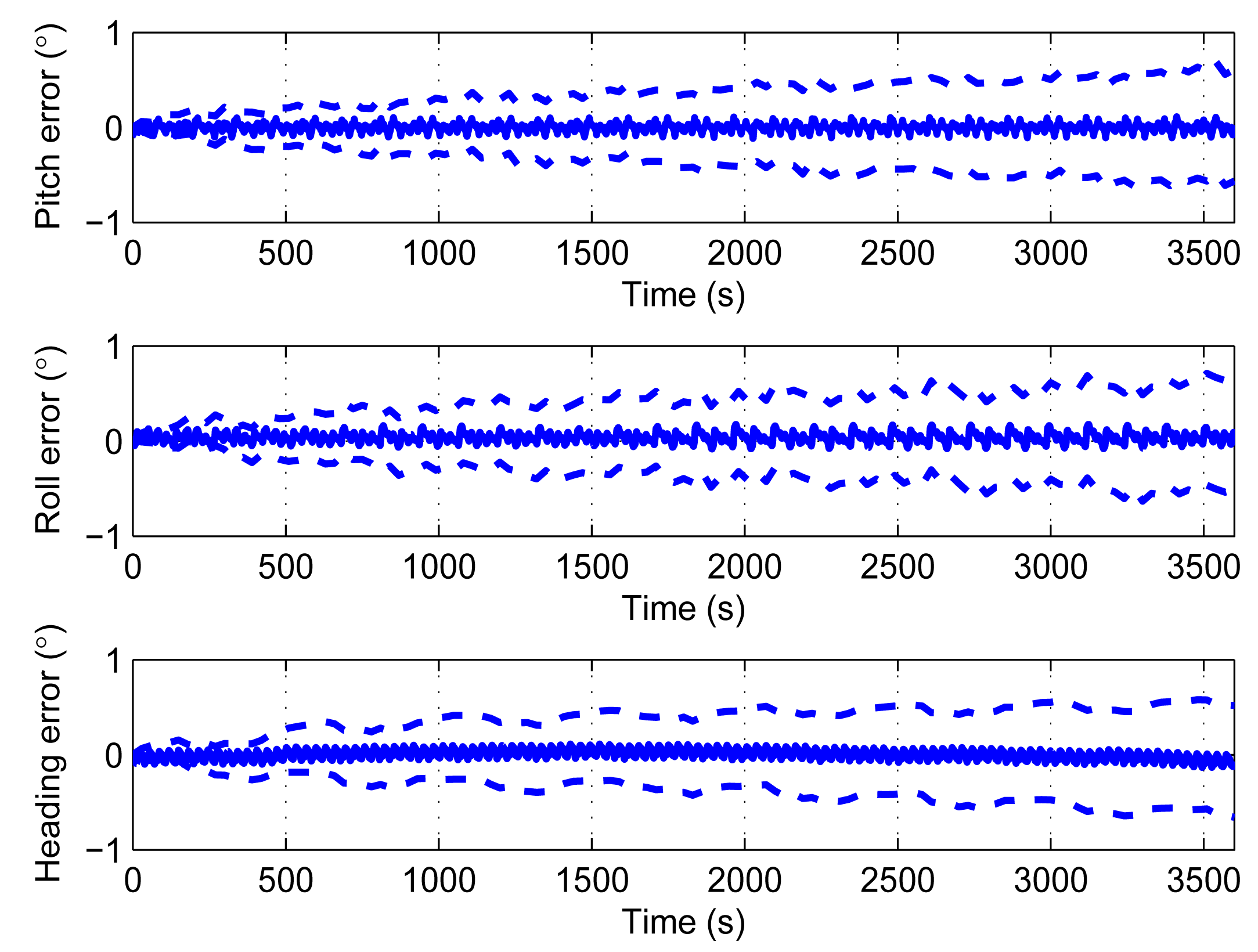
The third simulation adds additional noises to the sensors. The rates are 0.009°/s/ for bias, random data within ±0.25% for the scale factor. The simulation also runs 100 times. Figure 8 displays the average errors, as well as the respective 1σ envelopes.
In Figure 8, the average pitch error is within 0.15°, the average roll error is within 0.2°, and the average heading error is within 0.15°. The average errors are not growing with time. Although the average attitude and heading errors keep steady, its 1σ envelopes are increasing with time. After 3600 s, the errors reach 0.5° for both attitude and heading. So, with real sensors, the main error source is the random noises which cannot be compensated by rotation.
6. Experimental Results
Three experiments are carried out on the AHRS shown in Figure 1 to demonstrate the performance with real sensors. The parameters of the sensors are as follows:
Gyroscope: bias stability: around 15°/h, noise: 0.009°/s/ , axis misalignment: 0.6°;
Accelerometers: accuracy: 5 mg;
Rotation encoder: resolution: 0.03°.
The AHRS is fixed on an already calibrated turntable that the initial heading could be directly obtained from the turntable. The initial pitch and roll could be gathered from the accelerometers through two simple equations as [23]
The turntable keeps still in the first experiment. It means that the pitch, roll and heading are stable. The attitude and heading errors are the output drift. The first experiment is carried out three times and each one lasts 1800 s. The results are shown in Table 3. We take the first one as an example to give the experiment details. The results are performed from Figure 9, 10 and Figure 11.
Figure 9 displays the outputs of the rotation encoders within two rotation cycles. Owing to the rotation speed errors, one rotation cycle is not exactly 128 s.
Figure 10 gives the attitude and heading errors before the installation error compensation, while Figure 11 shows the results after the compensation. Both the errors in Figures 10 and 11 are oscillating within a range. However, it is clear that the range after the compensation is smaller. The statistics in Table 3 are based on Figure 11. The oscillatory ranges are all within 2°. According to the results of the simulations, these oscillations are caused by the scale factor errors and axis misalignment angles. Owing to the back and forth rotation mode, these errors would not increase. These results in Figure 11 are consistent with the simulations.
In the second experiment, the turntable performed a ±15°, 0.1 Hz swing on the heading to evaluate the performance of the AHRS in dynamic environment. The reason we choose heading as the swing axis is that, for most of the AHRS, a roughly known pitch and roll can still be obtained from the accelerometers using the Equations (37) and (38) in motion situations, while the heading could only be obtained from the integration of the gyroscopes. The experiment is also performed three times, and each one lasts for 3600 s. The results are displayed in Table 4. We also take the first one as an example to give the experiment details. The results are performed in Figures 12 and 13.
The original output data rate of the turntable is 1 Hz. The data rate is increased by using a sinusoid wave curve fitting to 100 Hz. Figure 12 displays the heading outputs of the AHRS and the turntable within 10 cycles. The time delay between two outputs is about 0.14 s. These delays are already fixed in Figure 12. Figure 13 shows the errors of this experiment. The installation errors are already compensated in these two figures. The errors are a little bit larger compared with the stand-still condition. The pitch and roll errors are about 3°, and the heading error is within 2°.
The third experiment is a comparison between the AHRS proposed by this paper (AHRS1) and a low cost digital magnetic compass based AHRS (AHRS2) to show that AHRS1 is more stable in some magnetic interference environment. The AHRS1 and AHRS2 are all put on the turntable. The turntable still performed a ±15°, 0.1 Hz swing on the heading. The experiment lasts for 800 s. For the first 400 s, we do not add any magnetic interference to these AHRSs. After 400 s, magnetic interference is added. The results are shown in Figures 14 and 15, and Table 5. In order to make waveforms clear, Figure 14 only shows the output between 300 s to 500 s.
For pitch and roll, the errors of AHRS2 are smaller than AHRS1, but the errors are on the same level. While for heading, the errors of AHRS1 and AHRS2 are on the same level before the magnetic interference is added. When the magnetic interference is added, the error statistics of AHRS1 keep small while the errors of AHRS2 are significantly increased.
7. Conclusions
A low cost and small size attitude and heading reference system based on MEMS inertial sensors is presented. The AHRS is based on a dual-axis rotation structure with a proper rotary scheme to compensate the attitude and heading drift caused by the large gyroscope biases, scale factor errors and axis misalignment errors. Also the installation angle error between the body frame and the rotation table's frame is calibrated through an optimization algorithm. Simulations and experiments are proposed to evaluate the performance of the AHRS. The attitude and heading drift are significantly reduced by the proper rotary scheme. The new AHRS is not affected by magnetic interference. The attitude error is about 3° and the heading error is less than 3°, which are at least 5 times better than the non-rotation condition. Furthermore, the errors are almost just oscillating within a range. Most of these oscillatory errors are caused by the scale factor errors and axis misalignment errors with additional rotations. So we believe that the accuracy could be further improved if the scale factor errors and axis misalignment errors of the MEMS gyroscopes could be reduced.
Acknowledgments
This work is supported by the National High-tech Research and Development Program of China (2013AA09A414).
Author Contributions
Li Kang studies the rotary schemes and error compensation theory of the AHRS. Kaichen Song designs the mechanical structure of the AHRS. Lingyun Ye and Yang Zhou collect the experiment data.
Conflicts of Interest
The authors declare no conflict of interest.
References
- Jalving, B.; Gade, K.; Svartveit, K.; Willumsen, A.; Sorhagen, R. DVL velocity aiding in the HUGIN 1000 integrated inertial navigation system. Model. Identif. Control 2004, 25, 223–235. [Google Scholar]
- Hegrenaes, O.; Berglund, E. Doppler water-track aided inertial navigation for autonomous underwater vehicle. Proceedings of Oceans 2009—Europe, Bremen, Germany, 11–14 May 2009; pp. 406–415.
- Fallon, M.; Papadopoulos, G.; Leonard, J. Cooperative AUV Navigation Using a Single Surface Craft. In Field and Service Robotics; Howard, A., Iagnemma, K., Kelly, A., Eds.; Springer: Berlin/Heidelberg, Germany, 2010; Volume 62, pp. 331–340. [Google Scholar]
- Wang, M.; Yang, Y.; Hatch, R.R.; Zhang, Y. Adaptive filter for a miniature MEMS based attitude and heading reference system. Proceedings of Position Location and Navigation Symposium, Monterey, CA, USA, 26–29 April 2004; pp. 193–200.
- Zhu, R.; Sun, D.; Zhou, Z.; Wang, D. A linear fusion algorithm for attitude determination using low cost MEMS-based sensors. Measurement 2007, 40, 322–328. [Google Scholar]
- Hanse, J.G. Honeywell MEMS inertial technology & product status. Proceedings of Position Location and Navigation Symposium, Monterey, CA, USA, 26–29 April 2004; pp. 43–48.
- Hong, S.K.; Park, S. Minimal-drift heading measurement using a MEMS gyro for indoor mobile robots. Sensors 2008, 8, 7287–7299. [Google Scholar]
- Sun, W.; Xu, A.-G.; Che, L.-N.; Gao, Y. Accuracy improvement of SINS based on IMU rotational motion. IEEE Aerospace Electron. Syst. Mag. 2012, 27, 4–10. [Google Scholar]
- Sun, F.; Wang, Q. Researching on the compensation technology of rotating mechanism error in single-axis rotation strapdown inertial navigation system. Proceedings of 2012 International Conference on Mechatronics and Automation (ICMA), Chengdu, China, 5–8 August 2012; pp. 1767–1772.
- Yuan, B.; Liao, D.; Han, S. Error compensation of an optical gyro INS by multi-axis rotation. Meas. Sci. Technol. 2012, 23. [Google Scholar] [CrossRef]
- Lahham, J.I.; Wigent, D.J.; Coleman, A.L. Tuned support structure for structure-borne noise reduction of inertial navigator with dithered ring laser gyros (RLG). Proceedings of Position Location and Navigation Symposium, San Diego, CA, USA, 13–16 March 2000; pp. 419–428.
- Lahham, J.; Brazell, J. Acoustic noise reduction in the MK 49 ship's inertial navigation system (SINS). Proceedings of Position Location and Navigation Symposium, Monterey, CA, USA, 23–27 March 1992; pp. 32–39.
- Levinson, E.; Ter Horst, J.; Willcocks, M. The next generation marine inertial navigator is here now. Proceedings of Position Location and Navigation Symposium, Las Vegas, NV, USA, 11–15 April 1994; pp. 121–127.
- Song, N.; Cai, Q.; Yang, G.; Yin, H. Analysis and calibration of the mounting errors between inertial measurement unit and turntable in dual-axis rotational inertial navigation system. Meas. Sci. Technol. 2013, 24. [Google Scholar] [CrossRef]
- Iozan, L.I.; Kirkko-Jaakkola, M.; Collin, J.; Takala, J.; Rusu, C. North finding system using a MEMS gyroscope. Proceedings of European Navigation Conference on Global Navigation Satellite Systems, Braunschweig, Germany, 19–21 October 2010.
- Wei, Y.L.; Lee, M.C. Mobile robot autonomous navigation using MEMS gyro north finding method in global urban system. Proceedings of 2011 International Conference on Mechatronics and Automation (ICMA), Beijing, China, 7–10 August 2011; pp. 91–96.
- Renkoski, B.M. The Effect of Carouseling on MEMS IMU Performance for Gyrocompassing Applications. In Master's Thesis; Department of Aeronautics and Astronautics, Massachusetts Institute of Technology: Cambridge, MA, USA, 2008. [Google Scholar]
- Savage, P.G. Strapdown inertial navigation integration algorithm design part 1: Attitude algorithms. J. Guid. Control Dyn. 1998, 21, 19–28. [Google Scholar]
- Han, S.; Wang, J. A novel initial alignment scheme for low-cost INS aided by GPS for land vehicle applications. J. Navig. 2010, 63, 663–680. [Google Scholar]
- Kong, X.; Nebot, E.M.; Durrant-Whyte, H. Development of a nonlinear PSI-angle model for large misalignment errors and its application in INS alignment and calibration. Proceedings of the 1999 IEEE International Conference on Robotics and Automation, Detroit, MI, USA, 10–15 May 1999; Volume 1432, pp. 1430–1435.
- Hong, H.S.; Lee, J.G.; Park, C.G. Performance improvement of in-flight alignment for autonomous vehicle under large initial heading error. IEE Proc.-Radar Sonar Navig. 2004, 151, 57–62. [Google Scholar]
- Eggert, D.W.; Lorusso, A.; Fisher, R.B. Estimating 3-D rigid body transformations: A comparison of four major algorithms. Mach. Vis. Appl. 1997, 9, 272–290. [Google Scholar]
- Noureldin, A.; Karamat, T.B.; Georgy, J. Fundamentals of Inertial Navigation, Satellite-Based Positioning and Their Integration; Springer: Berlin/Heidelberg, Germany, 2013. [Google Scholar]


| Mean | STD | Max | Min | ||
|---|---|---|---|---|---|
| Pitch error (°) | AHWR | −0.039 | 0.758 | 1.406 | −1.401 |
| AHNR | 7.839 | 4.590 | 15.850 | 0 | |
| Roll error (°) | AHWR | −0.573 | 0.597 | 0.592 | −1.603 |
| AHNR | 6.626 | 3.568 | 12.360 | 0 | |
| Heading error (°) | AHWR | 0.651 | 0.662 | 1.884 | −0.603 |
| AHNR | 7.458 | 4.323 | 15.001 | 0 | |
| Mean | STD | Max | Min | ||
|---|---|---|---|---|---|
| Pitch error (°) | Average of 100 times | 0.002 | 0.787 | 1.462 | −1.407 |
| 1σ envelopes | 0.031 | ||||
| Roll error (°) | Average of 100 times | −0.574 | 0.573 | 0.299 | −1.449 |
| 1σ envelopes | 0.026 | ||||
| Heading error (°) | Average of 100 times | 0.659 | 0.574 | 1.539 | −0.244 |
| 1σ envelopes | 0.014 | ||||
| Mean | STD | Max | Min | ||
|---|---|---|---|---|---|
| Pitch error (°) | 1 | 0.015 | 0.514 | 1.209 | −1.048 |
| 2 | 0.707 | 0.952 | 2.837 | −1.520 | |
| 3 | −0.861 | 0.690 | 0.831 | −2.780 | |
| Roll error (°) | 1 | −0.359 | 0.509 | 0.889 | −1.909 |
| 2 | 0.167 | 0.908 | 1.987 | −2.245 | |
| 3 | 0.410 | 0.899 | 2.425 | −1.227 | |
| Heading error (°) | 1 | −0.184 | 0.301 | 0.687 | −1.050 |
| 2 | −0.264 | 0.603 | 1.055 | −1.707 | |
| 3 | 0.290 | 0.884 | 2.414 | −1.493 | |
| Mean | STD | Max | Min | ||
|---|---|---|---|---|---|
| Pitch error (°) | 1 | −0.248 | 0.871 | 2.223 | −2.701 |
| 2 | −0.354 | 0.826 | 2.017 | −2.939 | |
| 3 | −0.255 | 0.743 | 2.205 | −2.456 | |
| Roll error (°) | 1 | −0.835 | 0.908 | 1.888 | −3.332 |
| 2 | 0.009 | 1.124 | 2.989 | −2.924 | |
| 3 | −0.151 | 1.018 | 2.535 | −2.935 | |
| Heading error (°) | 1 | −0.111 | 0.491 | 1.606 | −1.685 |
| 2 | −0.137 | 0.732 | 1.751 | −2.054 | |
| 3 | −0.484 | 1.028 | 2.861 | −2.867 | |
| Mean | STD | Max | Min | ||
|---|---|---|---|---|---|
| Pitch error (°) | AHRS1 | −0.441 | 0.593 | 1.065 | −2.127 |
| AHRS2 | 0.122 | 0.044 | 0.247 | 0.002 | |
| Roll error (°) | AHRS1 | −0.149 | 0.935 | 1.843 | −2.302 |
| AHRS2 | −0.080 | 0.061 | 0.063 | −0.318 | |
| Heading error (°) before interference added | AHRS1 | −0.388 | 0.663 | 1.132 | −2.069 |
| AHRS2 | −0.146 | 0.755 | 1.855 | −3.378 | |
| Heading error (°) after interference added | AHRS1 | −0.919 | 0.709 | 0.751 | −2.457 |
| AHRS2 | −8.466 | 7.091 | 23.860 | −48.260 | |
© 2014 by the authors; licensee MDPI, Basel, Switzerland. This article is an open access article distributed under the terms and conditions of the Creative Commons Attribution license ( http://creativecommons.org/licenses/by/4.0/).
Share and Cite
Kang, L.; Ye, L.; Song, K.; Zhou, Y. Attitude Heading Reference System Using MEMS Inertial Sensors with Dual-Axis Rotation. Sensors 2014, 14, 18075-18095. https://doi.org/10.3390/s141018075
Kang L, Ye L, Song K, Zhou Y. Attitude Heading Reference System Using MEMS Inertial Sensors with Dual-Axis Rotation. Sensors. 2014; 14(10):18075-18095. https://doi.org/10.3390/s141018075
Chicago/Turabian StyleKang, Li, Lingyun Ye, Kaichen Song, and Yang Zhou. 2014. "Attitude Heading Reference System Using MEMS Inertial Sensors with Dual-Axis Rotation" Sensors 14, no. 10: 18075-18095. https://doi.org/10.3390/s141018075