A Tensor-Based Subspace Approach for Bistatic MIMO Radar in Spatial Colored Noise

Abstract
: In this paper, a new tensor-based subspace approach is proposed to estimate the direction of departure (DOD) and the direction of arrival (DOA) for bistatic multiple-input multiple-output (MIMO) radar in the presence of spatial colored noise. Firstly, the received signals can be packed into a third-order measurement tensor by exploiting the inherent structure of the matched filter. Then, the measurement tensor can be divided into two sub-tensors, and a cross-covariance tensor is formulated to eliminate the spatial colored noise. Finally, the signal subspace is constructed by utilizing the higher-order singular value decomposition (HOSVD) of the cross-covariance tensor, and the DOD and DOA can be obtained through the estimation of signal parameters via rotational invariance technique (ESPRIT) algorithm, which are paired automatically. Since the multidimensional inherent structure and the cross-covariance tensor technique are used, the proposed method provides better angle estimation performance than Chen's method, the ESPRIT algorithm and the multi-SVD method. Simulation results confirm the effectiveness and the advantage of the proposed method.1. Introduction
Recently, multiple-input multiple-output (MIMO) radar [1–3] has drawn increasing attention and has become a hot research topic in the area of radar. MIMO radar uses multiple antennas to emit simultaneously orthogonal waveforms instead of the coherent waveforms, which are used in the phased-array radar, and this waveform diversity endows MIMO radar with superior performance relative to phased-array radar. Based on the configuration of transmit and receive antennas, MIMO radar can be grouped into two classes. One is called statistical MIMO radar [2], which can solve the problem of target scintillation, due to the widely spaced transmit/receive antennas. The other is called colocated MIMO radar [3], including bistatic and monostatic MIMO radar [4,5], whose transmit antennas and receive antennas are close spaced. The colocated MIMO radar can obtain the virtual aperture, which is larger than the real aperture, so it brings a lot of advantages, such as narrower beamwidth and lower sidelobes, higher angular resolution and angular estimation accuracy.
Angle estimation is an important aspect in array signal processing and MIMO radar [6–14]. In bistatic MIMO radar, the direction of departure (DOD) and the direction of arrival (DOA) need to be estimated simultaneously. In [8], a two-dimensional Capon estimator is applied to estimate DOD and DOA, which are paired automatically. However, it has a heavy computational burden owing to the two-dimensional spectrum searching. In order to alleviate the computational burden, the estimation of signal parameters via rotational invariance technique (ESPRIT) [9,10] is employed to DOD and DOA estimation. The rotational invariance properties of both the transmit and receive arrays are investigated in [9], then the DOD and DOA are determined through two independent 1D ESPRITs. However, an additional pairing operation is required. In [10], the relationship between two 1D ESPRIT is investigated. In [11], the real-valued ESPRIT (unitary ESPRIT) is proposed to estimate DOD and DOA. It has lower computational complexity and slightly better angle estimation performance compared with ESPRIT [9,10]. A multi-singular value decomposition (multi-SVD) method is presented for DOD and DOA estimation in [12]. It provides better angle estimation than the traditional eigenvalue decomposition (EVD)/SVD method. The above schemes can only be used for angle estimation in the presence of spatial Gaussian white noise. In [13], an ESPRIT-based method for bistatic MIMO radar DOD and DOA estimation is proposed, which can eliminate spatial colored noise. However, it is only effective for three transmit antennas configuration. By dividing the transmit array into two subarrays, a combined ESPRIT and SVD of the cross-correlation matrix method (denoted as Chen's method) is presented in [14], which is effective for MIMO radar with three or more transmit antennas to eliminate the influence of spatial colored noise.
However, in the subspace methods [13,14], the received signals are stacked into a special structure matrix, ignoring the multidimensional structure inherent in the received signals after matched filters. In this paper, a tensor-based frame is considered for the received signals, which exploits the multidimensional inherent structure and a novel tensor-based subspace for bistatic MIMO radar in the presence of spatial colored noise is proposed. Firstly, utilizing the multidimensional structure inherent in the received signals after matched filters, the received signals can be packed into a third-order measurement tensor. Then, the measurement tensor is divided into two sub-tensors, and a cross-covariance tensor is formulated to eliminate the spatial colored noise by exploiting the orthogonal characteristic of matched filters. Finally, the higher-order singular value decomposition (HOSVD) technique is employed to formulate the signal subspace. The DOD and DOA are estimated through the ESPRIT algorithm, which are paired automatically. Theoretical analysis and simulation results validate that the proposed method suppresses spatial colored noise more efficiently and provides better angle estimation performance than Chen's method, the ESPRIT algorithm and the multi-SVD method, especially at the low signal-to-noise ratio (SNR) region.
The rest of the paper is organized as follows. The tensor basics and signal model are presented in Section 2. A tensor-based subspace approach for angle estimation in the presence of spatial colored noise is proposed in Section 3. The computational complexity of the method is evaluated in Section 4. In Section 5, simulation results are provided to verify the performance of the proposed algorithm. Finally, Section 6 concludes this paper.
Notation:Scalars, column vectors, matrices and tensor are expressed by regular, bold lowercase, bold uppercase and bold calligraphic letters, respectively. [A]i,j and
 i,j,k stand for the (i,j) and (i,j, k) element of a matrix, A, and a tensor,
. (·)H, (·)T, (·))−1 and (·)* denote the Hermitian transpose, transpose, inverse and complex conjugation without transposition, respectively. ⊗ and ⊙ denote the Kronecker operator and the Khatri-Rao product, respectively. diag(·) denotes the diagonalization operation, and arg(γ) denotes the phase of γ.
i,j,k stand for the (i,j) and (i,j, k) element of a matrix, A, and a tensor,
. (·)H, (·)T, (·))−1 and (·)* denote the Hermitian transpose, transpose, inverse and complex conjugation without transposition, respectively. ⊗ and ⊙ denote the Kronecker operator and the Khatri-Rao product, respectively. diag(·) denotes the diagonalization operation, and arg(γ) denotes the phase of γ.
2. Tensor Basics and Signal Model
2.1. Tensor Basics
For the readers' convenience, several tensor operations are introduced firstly, which refer to [15,16].
Definition 1 (Matrix Unfolding):The three standard unfoldings of a third-order tensor,
![Sensors 14 03897i6]() ∈ ℂI×J×K, denoted by [
∈ ℂI×J×K, denoted by [
![Sensors 14 03897i6]() ](1) ∈ ℂI×JK [
](1) ∈ ℂI×JK [
![Sensors 14 03897i6]() ](2) ∈ ℂJ×IK and [
](2) ∈ ℂJ×IK and [
![Sensors 14 03897i6]() ](3) ∈ ℂK×IJ, can be expressed as [[
](3) ∈ ℂK×IJ, can be expressed as [[
![Sensors 14 03897i6]() ](1)]i,(k−1)J+j = [
](1)]i,(k−1)J+j = [
![Sensors 14 03897i6]() ]i,j,k, [[
]i,j,k, [[
![Sensors 14 03897i6]() ](2)]j,(i−1)K+k = [
](2)]j,(i−1)K+k = [
![Sensors 14 03897i6]() ]i,j,k and [[
]i,j,k and [[
![Sensors 14 03897i6]() ](3)]k,(j−1)I + i = [
](3)]k,(j−1)I + i = [
![Sensors 14 03897i6]() ]i,j,k, respectively.
]i,j,k, respectively.Definition 2 (Mode-n Tensor-Matrix Product):The mode-n product of
![Sensors 14 03897i6]() ∈ ℂI1×I2×⋯×IN by a matrix, A ∈ ℂJn×In, is denoted by
∈ ℂI1×I2×⋯×IN by a matrix, A ∈ ℂJn×In, is denoted by
![Sensors 14 03897i1]() =
=
![Sensors 14 03897i6]() ×n A, where
×n A, where
![Sensors 14 03897i1]() ∈ ℂI1×I2×⋯×In−1×Jn×In+1×⋯×IN and
∈ ℂI1×I2×⋯×In−1×Jn×In+1×⋯×IN and
Definition 3 (The Properties of the Mode Product):The properties of the mode product are shown as follows:

2.2. Bistatic MIMO Radar Signal Model
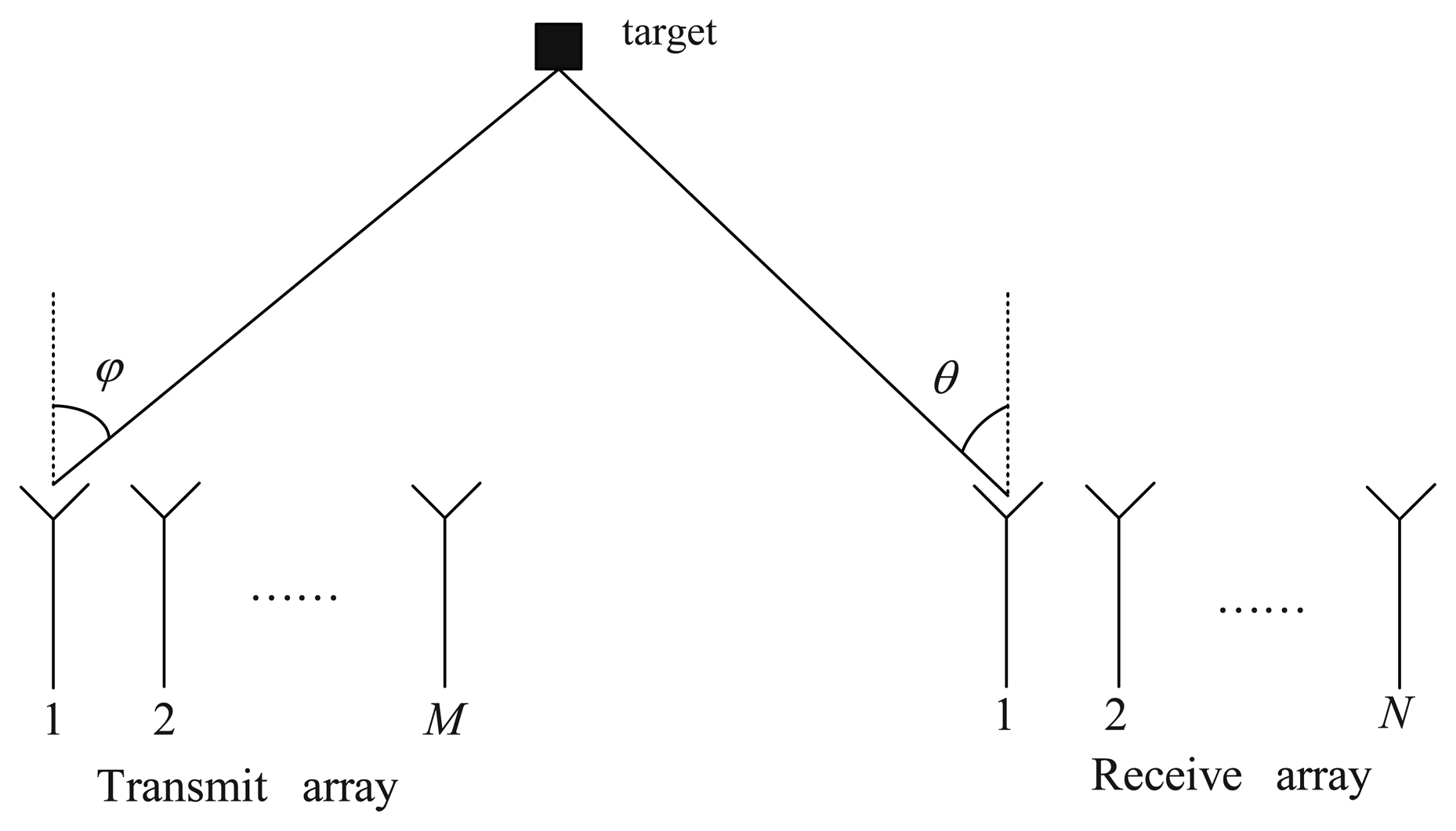
Consider a narrowband bistatic MIMO radar system with M colocated antennas for the transmit array and N colocated antennas for the receive array, shown in Figure 1.
Both the transmit array and receive array are uniform linear arrays (UALs), and the inter-element spaces of the transmit and receive arrays are half-wavelength. At the transmit array, the transmit antennas emit the orthogonal waveforms S = [s1, s2, ⋯, sM]T ∈ ℂM×K, where K is the number of samples per pulse period. All the targets are modeled as a point-scatterer in the far-field, and it is assumed that there are P uncorrelated targets in the same range-bin of interest. and are the DOD and DOA with respect to the transmit and receive array normal, respectively. We consider a coherent processing interval (CPI) consisting of L pulses, then the baseband received signal for the l-th pulse period at the output of the receive array can be written as [3,14]:
3. Tensor-Based Subspace Approach for Angle Estimation
According to Equation (4), the received signals are matched with all the transmitted waveforms. Then, we have:
In the conventional subspace-based methods, the received signals in Equation (5) are packed into a special structure matrix as Y = [vec(Y1)), vec(Y2),…, vec(YL)], which ignores the multidimensional structure inherent in the received signals. Based on the concept of Definition 1, it can be seen that the received signals for each pulse is a slice of a third-order tensor along the pulse direction. Therefore, by collecting L pulses, a third-order measurement tensor,
 , is constructed, which is satisfied with
. According to
, it is implied that the output of the colored noise has the orthogonal characteristic between different matched filters. In order to exploit this characteristic, the measurement tensor,
, is divided into two sub-tensors, which is shown as:
, is constructed, which is satisfied with
. According to
, it is implied that the output of the colored noise has the orthogonal characteristic between different matched filters. In order to exploit this characteristic, the measurement tensor,
, is divided into two sub-tensors, which is shown as:
1 and
2, are obtained from different matched filters, i.e,
1 is the output of the first M1 matched filters and
2 is the output of the residual M2 = M − M1 matched filters. Thus, we have
owing to
. Then, a fourth-order cross-covariance tensor,
 21 ∈ ℂN×M2×N×M1, is formulated as:
21, is not affected by the additive spatial colored noise. According to Equation (8), the relationship between the cross-correlation matrix
and the cross-covariance tensor,
21, is shown in Equation (9).
21 ∈ ℂN×M2×N×M1, is formulated as:
21, is not affected by the additive spatial colored noise. According to Equation (8), the relationship between the cross-correlation matrix
and the cross-covariance tensor,
21, is shown in Equation (9).Then, the HOSVD [15,16] of the cross-covariance tensor,
21, yields:
21 is a rank-P tensor, a cross-covariance subspace tensor,
 s, can be estimated by using the truncated HOSVD of
21, which can be written as:
s, can be estimated by using the truncated HOSVD of
21, which can be written as:
 s into Equation (11), we have:
According to the relationship between the cross-correlation matrix and its corresponding cross-covariance tensor in Equation (9) and the Definition 3, a new cross-correlation matrix, R̄21, is reconstructed from
s, which can be expressed as:
In the subspace method [14], the signal subspace matrix, Us, is determined by using the truncated SVD of R21, i.e., R21 ≈ UsΛsVs. Inserting it into Equation (13), we have:
According to Equation (14), using the truncated SVD of R̄21, the signal subspace, Ūs, can be written as:
According to Equation (15), it is indicated that the signal subspace, Ūs, and Us span the same subspace. Hence, there exists a nonsingular matrix, T ∈ ℂP×P, satisfied with Ūs = (A ⊙ B)T. After obtaining the signal subspace, Ūs the ESPRIT algorithm [7,8] is applied to estimate the DOD and DOA.
In order to estimate both the DOD and DOA, the signal subspace, Ūs is divided into four submatrices: Ūs1 = Γ1Ūs, Ūs2 = Γ2Ūs, Ūs3 = Γ3Ūs and Ūs4 = Γ4Ūs, where , , , , , . In doing so, we have:
4. Computational Complexity Analysis and Remark
In order to analyze the computational complexity of the proposed method, it is necessary to know the complexity of the SVD algorithm. There are a lot of methods to compute SVD, and the computational complexities of them are different. In [17], it has been pointed out that orthogonal iteration is an efficient solution for SVD algorithm. The computational complexity of an M × N matrix truncated to rank r is O(krMNr) by using this orthogonal iteration, where kr is a constant that depends on the design of the algorithm. The main computational burden of the proposed method, multi-SVD method, Chen's method and ESPRIT algorithm is the estimation of the signal subspace. In order to estimate the signal subspace, Ūs the proposed method needs to calculate the truncated HOSVD of
21 and the truncated SVD of R̄21. The truncated HOSVD of
21 is equivalent to the truncated SVD of all its matrix unfolding, which needs O(4krM1M2N2P). Additionally, the computational complexity of the truncated SVD of R̄21 is O(krM1M2N2P). The total computational complexity of the proposed method is O(5krM1M2N2P). In the multi-SVD method, the signal subspace is estimated by the truncated HOSVD of the third tensor,
. Thus, the computational complexity is O(3krMNLP). Chen's method only needs the truncated SVD of R21 to estimate the signal subspace, which needs O(krM1M2N2P). The ESPRIT algorithm uses the truncated SVD of the covariance matrix R = (1/L)YYH to estimate the signal subspace, which needs krM2P. According to the above analysis, the computational complexity of the proposed method is similar to the multi-SVD method, but higher than both Chen's method and the ESPRIT algorithm. However, the proposed method provides better angle estimation performance than all the aforementioned methods, which is demonstrated in the next section.
Remark 1: According to Equation (11), in order to obtain the signal subspace, Uis, of Ui (i = 1, 2, 3, 4), the necessary conditions for M1, M2, N and L are that: M1 ≥ P, M2 ≥ P, N ≥ P, L ≥ P. It is indicated that the maximum number of targets can be identified by the proposed method is min[M1,M2, N, L]. Thus, the number of targets that can be identified by the proposed method is smaller than ESPRIT algorithm. However, the proposed method performs well and provides better angle estimation performance in the presence of spatial colored noise, while the ESPRIT algorithm has marked performance degradation, especially in the low SNR region.
5. Simulation Results
In this section, some simulations are presented to evaluate the angle estimation performance of the proposed method in the presence of spatial colored noise. The multi-SVD algorithm [12], ESPRIT algorithm [10] and the method in [14] (denoted as Chen's method) are used to compare with the proposed method. We consider a MIMO radar system with M colocated antennas and N colocated antennas for the transmit and receive array, respectively. Both of the transmit array and receive array are half-wavelength spaced ULAs. M transmit antennas transmit M orthogonal waveforms, and the m-th transmitted waveform is the m-th row of S ∈ ℂK×K, where , and HK is the K × K Hadamard matrix. The number of samples per pulse period is K = 256, and the pulse repetition interval is Tr = 5 us. There exists three uncorrelated targets located at (φ1, θ1) = (30°, −30°), (φ2, θ2) = (−40°, 10°) and (φ3, θ3) = (10°, 10°), and the reflection coefficients of the targets are . The Doppler shifts are . The spatial colored noise is modeled as a spatial complex autoregressive (AR) model of second-order with the coefficients z = [1, −1,0.2] [12], and the root mean square error (RMSE) of the angle estimation is defined as:
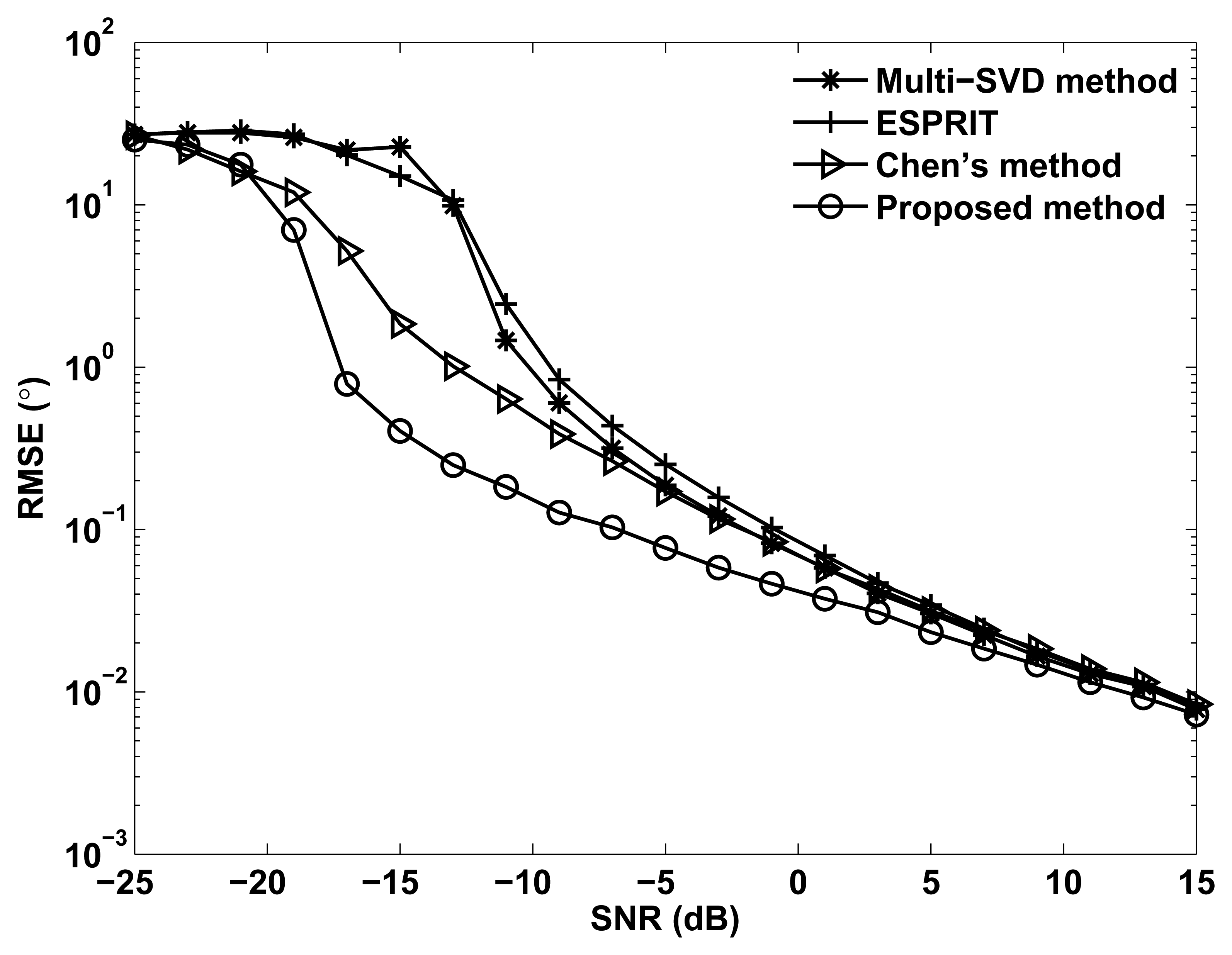
Figure 2 shows the RMSE of angle estimation of different methods versus SNR, where M = N = 12, M1 = 3, L = 100 and Q = 200. It is shown in Figure 2 that the ESPRIT and multi-SVD algorithm provide worse angle estimation performance than Chen's method and the proposed method, especially at the low SNR region. This is because the ESPRIT and multi-SVD method cannot eliminate the influence of spatial colored noise. It also can be observed that Chen's method provides better angle estimation performance than the ESPRIT algorithm, which is consistent with [14]. Owing to taking the multidimensional structure into account and using the cross-covariance tensor technique, the proposed method can eliminate the spatial colored noise more efficiently. Thus, the proposed method outperforms all aforementioned methods, especially at the low SNR region.
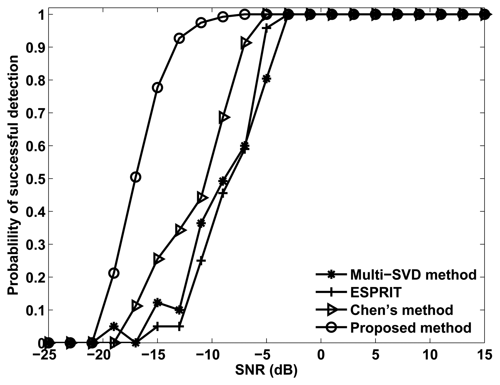
Figure 3 shows the probability of the successful detection of the different methods versus SNR, where M = N = 12, M1 = 3, L = 100 and Q = 200. Successful detection requires that the absolute error of both DOD and DOA for all three targets are within 0.5°. It can be seen from Figure 3 that all the methods exhibit a 100% successful detection at high SNR values. As the SNR decreases, the probability of successful detection decreases for each method at a certain point, which is known as the SNR threshold. It also can be seen that the proposed method has a lower SNR threshold than Chen's method, ESPRIT and the multi-SVD method, owing to the super capability of eliminating the spatial colored noise.
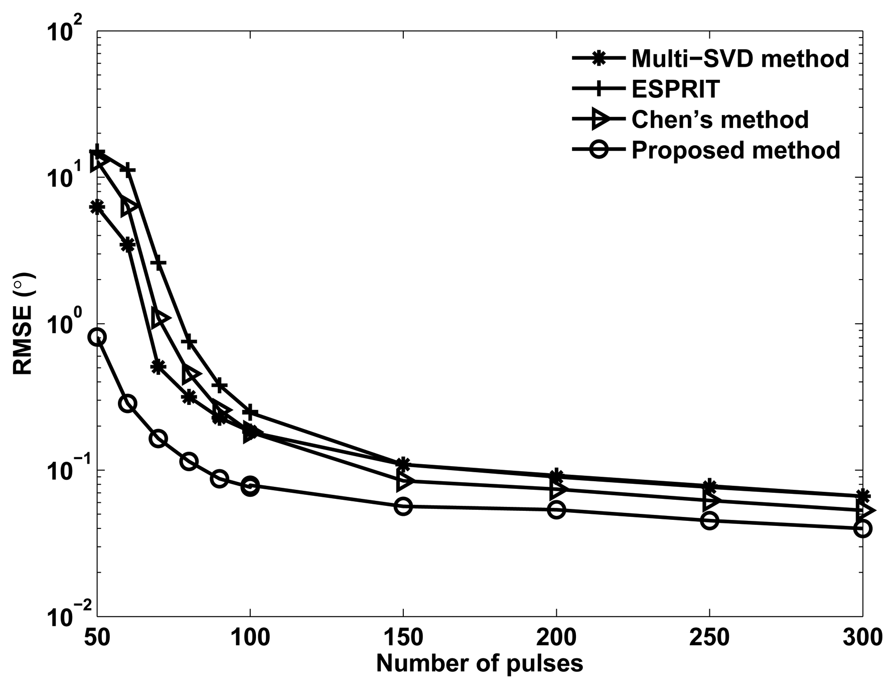
Figure 4 shows the RMSE of angle estimation of different methods versus the number of pulses, where M = N = 12, M1 = 3, SNR= −5dB and Q = 200. It can be seen in Figure 4 that the angle estimation performance of all methods can be improved with pulse increases, and the proposed method provides better angle estimation performance than Chen's method, ESPRIT and the multi-SVD algorithm.
6. Conclusions
In this paper, a tensor-based subspace approach is presented to DOD and DOA estimation for bistatic multiple-input multiple-output (MIMO) radar in the presence of spatial colored noise. The proposed method exploits the the multidimensional structure inherent in the received signals to construct a third-order measurement tensor. Then, two sub-tensors are obtained from the measurement tensor, which can be used to formulate a cross-covariance tensor for eliminating the influence of spatial colored noise. Finally the DOD and DOA can be estimated in conjunction with the ESPRIT method. The proposed method has better angle estimation performance than Chen's method, ESPRIT and the multi-SVD method, especially at the low SNR region. Several simulation results have verified the performance of the proposed method.
Acknowledgments
This work was supported by the New Century Excellent Talents Support Program (NCET-11-0827), innovation of science and technology talents in harbin (2013RFXXJ016) and fundamental research runs for the central universities (HEUCFX41308, HEUCFZ1110).
References
- Fishler, E.; Haimovich, A.; Blum, R.; Chizhik, D.; Cimini, L.; Valenzuela, R. MIMO Radar: An Idea Whose Time has Come. Proceedings of the IEEE radar Conference, Philadelphia, PA, USA, 26–29 April 2004; pp. 71–78.
- Haimovich, A.M.; Blum, R.; Cimini, L. MIMO radar with widely separated antennas. IEEE Signal Process. Mag. 2008, 25, 116–129. [Google Scholar]
- Li, J.; Stoica, P. MIMO radar with colocated antennas. IEEE Signal Process. Mag. 2007, 24, 106–114. [Google Scholar]
- Nion, D.; Sidiropoulos, N.D. Tensor algebra and multidimensional harmonic retrieval in signal processing for MIMO radar. IEEE Trans. Signal Process 2010, 58, 5693–5705. [Google Scholar]
- Wang, W.; Wang, X.; Song, H.; Ma, Y. Conjugate ESPRIT for DOA estimation in monostatic MIMO radar. Signal Process. 2013, 93, 2070–2075. [Google Scholar]
- Wang, J.; Huang, Z.; Zhou, Y. Direction-of-arrival estimation based on joint sparsity. Sensors 2011, 11, 9098–9108. [Google Scholar]
- Wang, Q.; Chen, H.; Zhao, G.; Chen, B.; Wang, P. An improved direction finding algorithm based on toeplitz approximationy. Sensors 2013, 13, 746–757. [Google Scholar]
- Yan, H.; Li, J.; Liao, G. Multitarget identification and localization using bistatic MIMO radar systems. EURASIP J. Adv. Signal Process. 2008. [Google Scholar] [CrossRef]
- Duofang, C.; Baixiao, C.; Guodong, Q. Angle estimation using ESPRIT in MIMO radar. Electron. Lett. 2008, 44, 770–771. [Google Scholar]
- Jinli, C.; Hong, G.; Weimin, S. Angle estimation using ESPRIT without pairing in MIMO radar. Electron. Lett. 2008, 44, 1422–1423. [Google Scholar]
- Zheng, G.; Chen, B.; Yang, M. Unitary ESPRIT algorithm for bistatic MIMO radar. Electronics Letters. Electron. Lett. 2012, 48, 179–181. [Google Scholar]
- Cheng, Y.; Yu, R.; Gu, H.; Sun, W. Multi-SVD based subspace estimation to improve angle estimation accuracy in bistatic MIMO radar. Signal Process. 2013, 93, 2003–2009. [Google Scholar]
- Jin, M.; liao, G.; Li, J. Joint DOD and DOA estimation for bistatic radar. Signal Process. 2009, 89, 244–251. [Google Scholar]
- Jinli, C.; Hong, G.; Weimin, S. A new method for joint DOD and DOA estimation in bistatic MIMO radar. Signal Process. 2010, 90, 714–718. [Google Scholar]
- Kolda, T.G.; Bader, B.W. Tensor decomposition and application. SIAM Rev. 2009, 51, 455–500. [Google Scholar]
- Lathauwer, L.D.; Moop, B.D.; Vandewalle, J. A mutilinear singular value decomposition. SIAM J. Matrix Anal. Appl. 2000, 21, 1253–1278. [Google Scholar]
- Golub, G.H.; Van Loan, C.F. Matrix Computations; Johns Hopkins University Press: Baltimore, MD, USA, 1996. [Google Scholar]


© 2014 by the authors; licensee MDPI, Basel, Switzerland. This article is an open access article distributed under the terms and conditions of the Creative Commons Attribution license ( http://creativecommons.org/licenses/by/3.0/).
Share and Cite
Wang, X.; Wang, W.; Li, X.; Wang, J. A Tensor-Based Subspace Approach for Bistatic MIMO Radar in Spatial Colored Noise. Sensors 2014, 14, 3897-3907. https://doi.org/10.3390/s140303897
Wang X, Wang W, Li X, Wang J. A Tensor-Based Subspace Approach for Bistatic MIMO Radar in Spatial Colored Noise. Sensors. 2014; 14(3):3897-3907. https://doi.org/10.3390/s140303897
Chicago/Turabian StyleWang, Xianpeng, Wei Wang, Xin Li, and Junxiang Wang. 2014. "A Tensor-Based Subspace Approach for Bistatic MIMO Radar in Spatial Colored Noise" Sensors 14, no. 3: 3897-3907. https://doi.org/10.3390/s140303897