Infrared Sensor-Based Temperature Control for Domestic Induction Cooktops

Abstract
: In this paper, a precise real-time temperature control system based on infrared (IR) thermometry for domestic induction cooking is presented. The temperature in the vessel constitutes the control variable of the closed-loop power control system implemented in a commercial induction cooker. A proportional-integral controller is applied to establish the output power level in order to reach the target temperature. An optical system and a signal conditioning circuit have been implemented. For the signal processing a microprocessor with 12-bit ADC and a sampling rate of 1 Ksps has been used. The analysis of the contributions to the infrared radiation permits the definition of a procedure to estimate the temperature of the vessel with a maximum temperature error of 5 °C in the range between 60 and 250 °C for a known cookware emissivity. A simple and necessary calibration procedure with a black-body sample is presented.1. Introduction
Induction cooktops are becoming one of the most popular appliances due to their safety, cleanliness, and high cooking performance [1–3]. In these system, the vessels are heated up by two dissipation phenomena: the induced currents and the ferromagnetic losses, both of them originated by varying magnetic fields generated by alternating medium frequency currents (20 to 100 kHz) flowing through a planar coil placed below the glass-ceramic surface [4,5] where the vessel is placed. The current frequency supplied by the power electronics depends on the power level selected by the user.
In commercial induction hobs, the control system is based on a closed-loop control [6–10], which adapts the power supplied to the cookware depending on the selected level by the user and safety conditions. However, the temperature in the cookware is a hidden variable to the control because no temperature probe can be placed in contact with the vessel due to product requirements. The temperature estimation system has to be located below the cooking surface as well as the inductor coils and the power electronics, thus, the temperature measurements are influenced by the effect of the cooking surface which has to be compensated in order to obtain an accurate temperature value of the vessel. It should be noted the importance of this parameter as a control variable in order to achieve advances features for domestic induction appliances, for example, assisted or automatic cooking.
High performance measurement systems would consist on temperature sensors placed inside the cookware, but this solution is not user-friendly. Alternative solutions have been proposed in order to overcome this drawback. One of those consists of a temperature measurement system based on a thermistor located under the glass-ceramic where the steady-state cookware temperature is assumed equal to the temperature of the in-contact glass [11,12]. The proposed system constitutes a simple and cost-effective solution, but it possesses some disadvantages, mainly due to the thermal inertia of the glass-ceramic, which introduces attenuation and time delays between the temperature of the cookware and the temperature of the glass. This effect becomes very critical in rapid heating transients due to the large difference between the measured temperature in the glass and the temperature in the cookware which implies that the cookware can reach high temperatures before the temperature sensor detects this situation. Additionally, this proposed system exhibits a strong dependence of the cookware-glass heat transfer due to the variability in the air gap between the cookware and the glass which influences in the dynamic of the measurement procedure. Other system based on inductive sensing [13] or radiation thermometry have been proposed in order to avoid these problems. This paper is focused on the latter one. Optical infrared (IR) sensors of different technologies, for example, photo-resistors [14], thermopiles [15–18], in array format for infrared computer vision [19–21] and including optical fibers [22] have been analyzed by many authors for other applications. However, the systems based on the infrared radiation detection by photodiodes are expected to achieve the best performance because of their rapid response, reduced cost, as well as the industrial applications of this technique in the cooking appliances industry.
The aim of this work is to describe the main features of a temperature control system based on an IR temperature sensor proposed in preceding works [23,24] as well as to provide the experimental verification to validate the performance of this cost-effective solution.
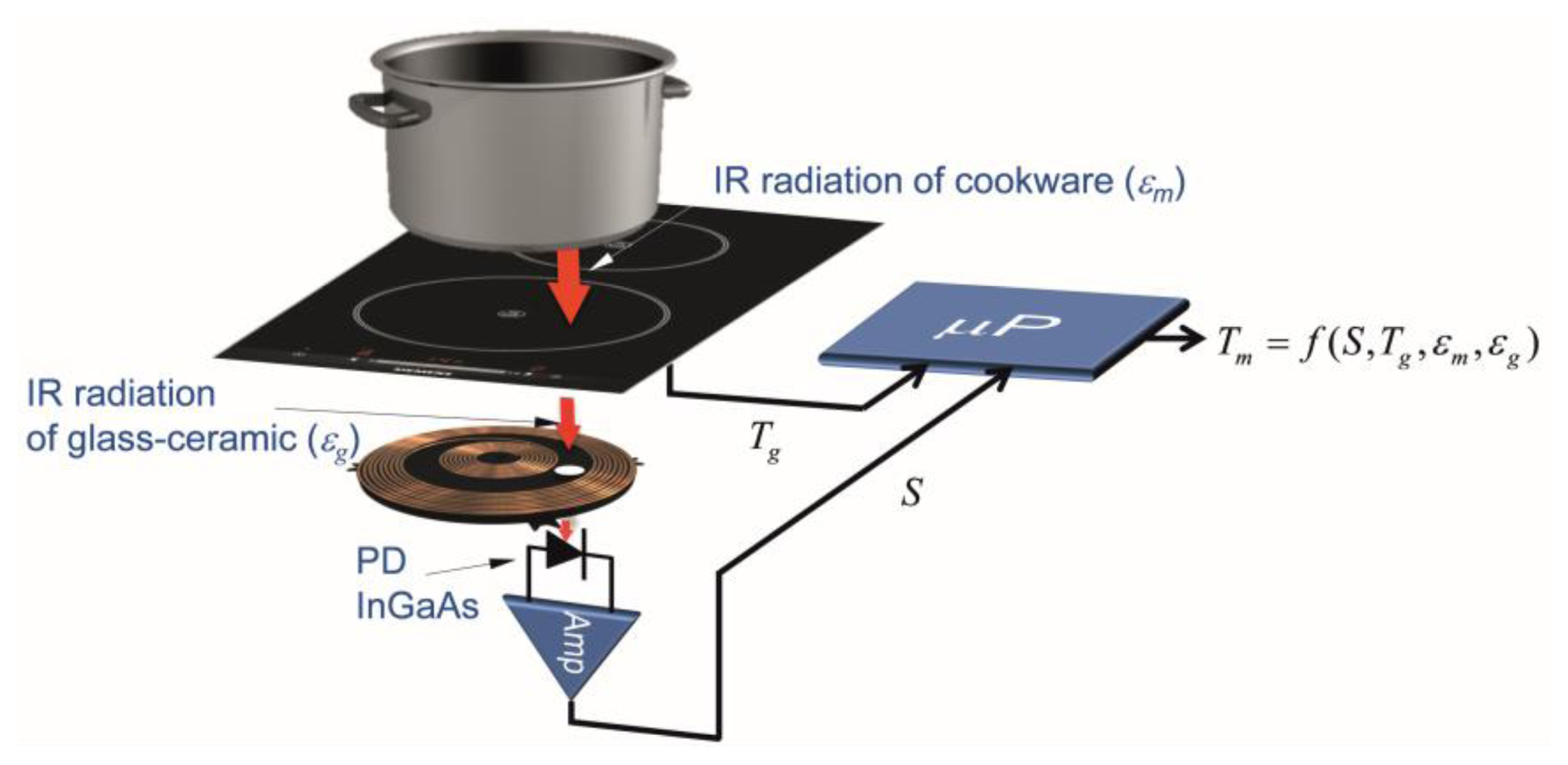
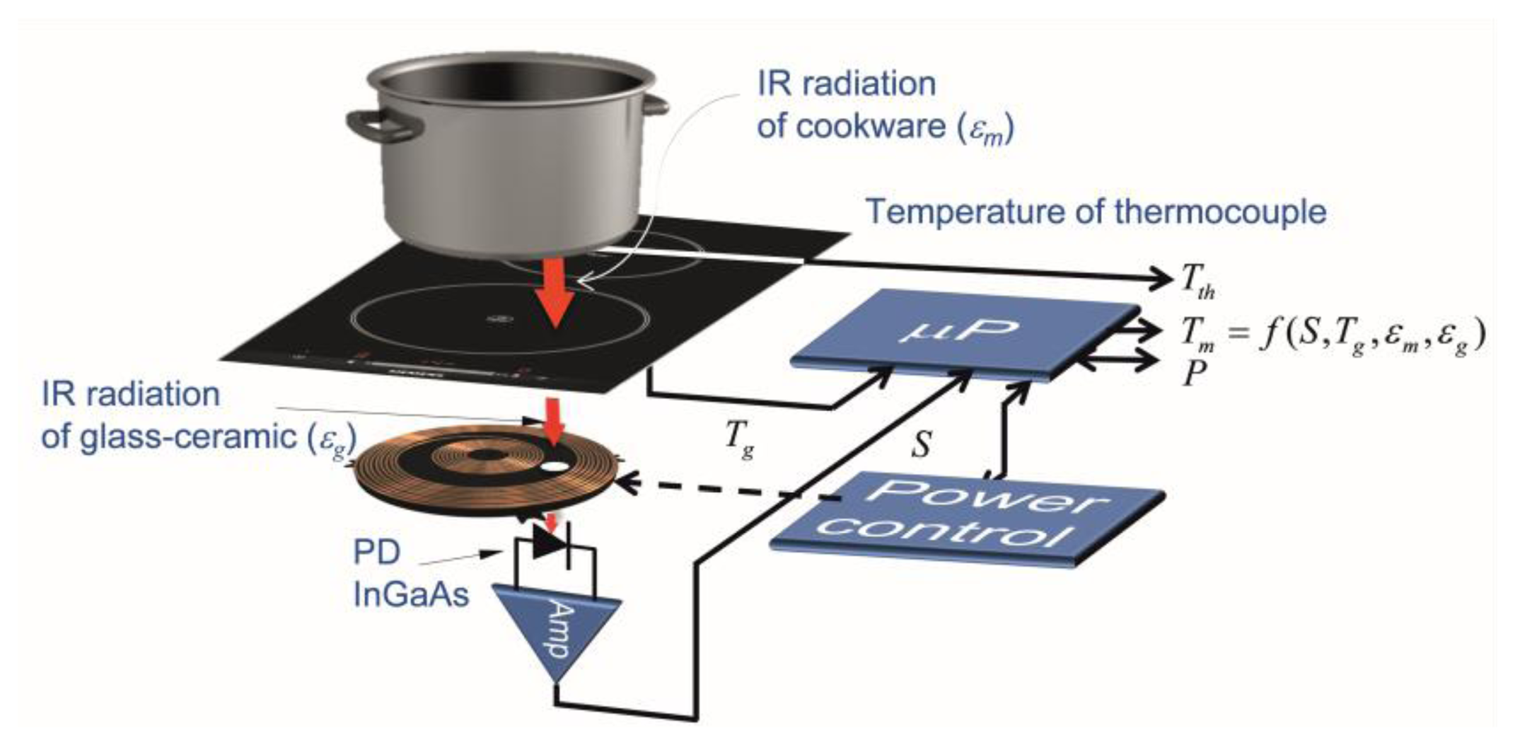
The temperature measurement system, shown in Figure 1, is based on the detection of the infrared light radiated by the bottom of the cookware and spectrally weighted by the glass-ceramic optical transmittance. The signal detected by the infrared photodiode (PD) depends on the temperature of the cookware, Tm, the temperature glass-ceramic, Tg, placed below the cookware, and the emissivities of the cookware, εm, and the glass-ceramic, εg, respectively. The power control system employs the measured temperature in order to adapt the power supplied by the inductor coil. The rapid response of the proposed system to temperature changes in the cookware is suitable to use to control the temperature of the cookware in rapid heating systems, for instance, induction cookers.
The paper is organized as follows: Section 2 introduces some theoretical background about the operational characteristics of the IR sensor depending on the temperatures and emissivities of the cookware and the glass-ceramic, respectively. Section 3 describes the electronic implementation of the proposed measurement system as well as the closed-loop power control and the calibration procedure of the IR sensor applied to compensate the effect of the glass-ceramic. Section 4 provides several experimental results in order to evaluate the main features of the proposed system. Finally, in Section 5 the main conclusions are drawn.
2. Analysis of IR Temperature Sensor
The temperature sensor is based on the detection of the infrared radiation by an extended range InGaAs PIN photodiode with a spectral responsivity up to 2,600 nm. A detailed analysis of the theoretical background given in the following subsections can be found in [24].
2.1. Infrared Signals in Domestic Induction Hobs
The model to analyze the thermal radiation of a metallic surface, (the bottom of the cookware), considered as a grey body of spectral emissivity, εm, at the temperature, Tm, in contact with a glass-ceramic top at the temperature, Tg, is shown in Figure 2. The glass-ceramic radiation contribution has to be taken into account because it also emits additional infrared radiation to that emitted by the cookware and transmitted by the glass-ceramic [25,26].
The total emission of the cookware/glass-ceramic system can be modeled through the addition of four signal contributions, as shown in Figure 2. The first contribution belongs to the radiation which arrives from the bottom of the cookware through the glass slab. The second one is the radiation emitted by the glass. The third contribution is the emerging radiation that results from adding the multiple reflections and transmitted beams emitted by the bottom of the cookware. The fourth contribution is the addition of the reflected and the transmitted radiation emitted by the glass-ceramic toward the bottom of the cookware. The total spectral emissive power emitted by the cookware-glass system in the normal direction, is:
The four contributions to E⊥ (λ,Tg,Tm) can be expressed as:
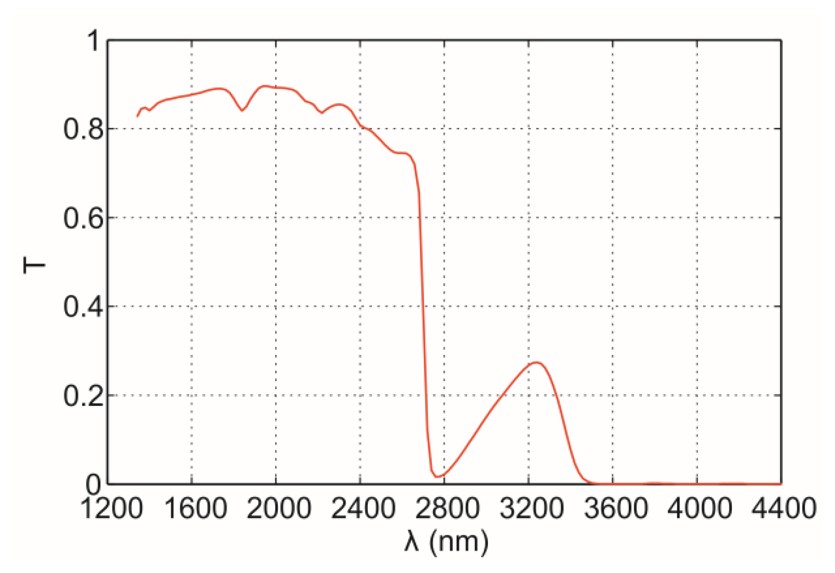
Figure 3 shows the typical transmittance spectrum, T, of conventional dark glass-ceramic top. Infrared radiation from metallic surface with wavelength above 2,600 nm is attenuated by the glass-ceramic material. Note that the use of extended photodiodes is adequate to detect IR radiation emitted by this kind of material.
2.2. Long-Range Single-Band Thermometry IR System
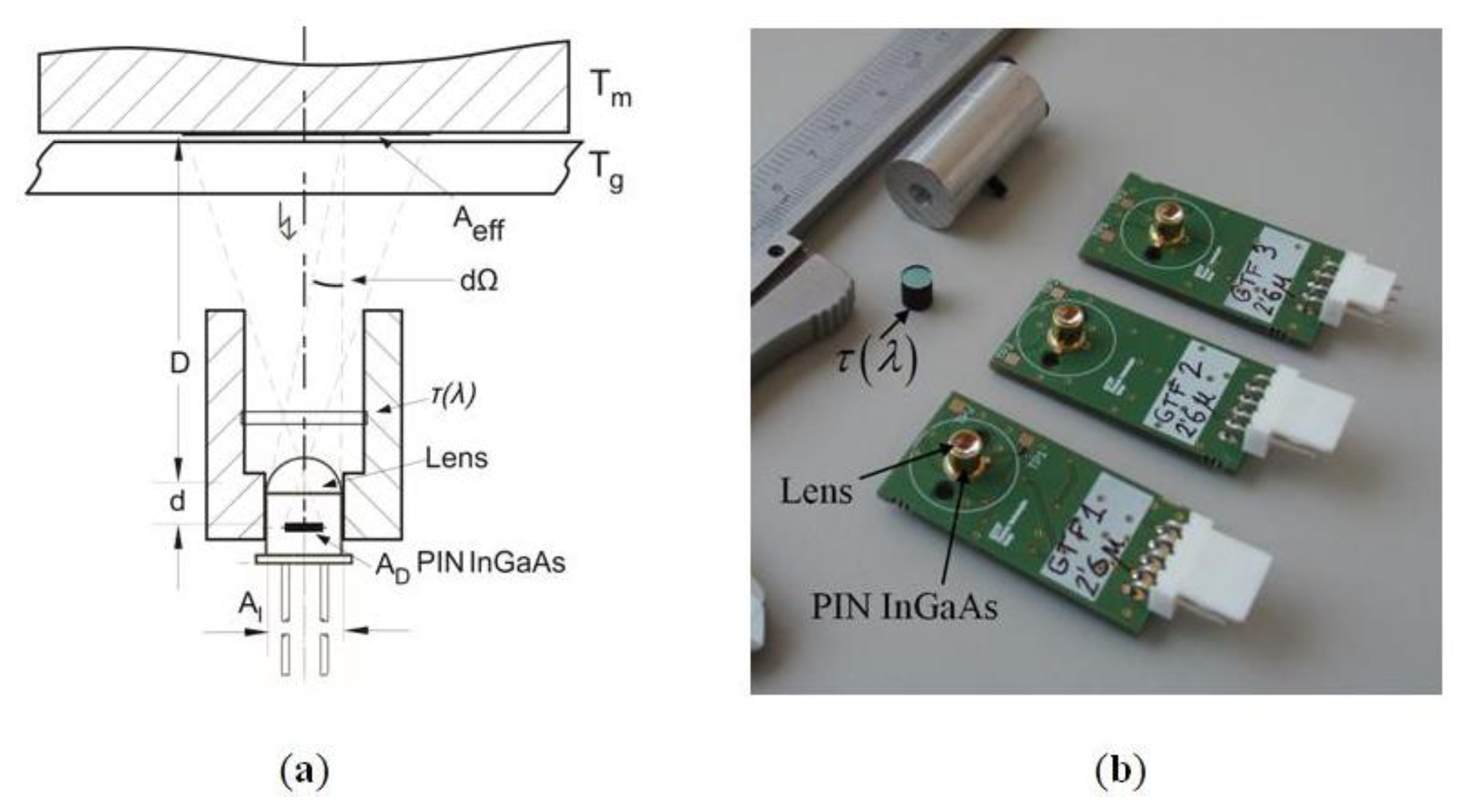
The optical temperature sensor system is shown in Figure 4a. The radiation is detected in a spectral band by a long-range IR InGaAs PIN photodiode with responsivity ℜ(λ), detection area AD, and placed at the focal point of the lens. Visible radiation from the environment is blocked by a high-pass optical filter with a cut-off wavelength of 1,200 nm and flat transmittance τ0 in the band from 1,200 to 2,600 nm. Figure 4b shows implemented optical system.
Assuming the independency with respect to the wavelength of the emissivity, the reflectance and the transmittance of the glass-ceramic and the cookware (grey body approach) in the region from 1,200 to 2,600 nm, the output voltage, S, due to the photo-current generated by a PIN can be expressed as [24]:
The expression f(T) can be regarded as f(T) = aTq, then:
The temperature Tm can be derived from the preceding expression with dependence on the output signal, S, the emissivity of the cookware, εm, the temperature, Tg, the transmittance, T, and the reflectance, R, of the glass-ceramic, as it is given as follows:
3. Electronic Implementation and Temperature Control System
The implementation of the IR sensor electronics and temperature control system are explained as follows:
3.1. Electronics of IR Sensor
Previous works demonstrate the usefulness of IR thermometry for cooking purposes within the range of frying temperatures ranging from 140 to 180 °C [24]. Unfortunately, not so good temperature estimation was achieved at temperatures below 110 °C because the photocurrent of a standard InGaAs PIN PD is comparable to the noise of the associated electronics. However, the proposed IR system is designed to measure temperatures ranging from 60 to 250 °C, therefore, an infrared detector with a long wavelength cut-off at 2,600 nm is needed.
InGaAs PIN photodiodes are photovoltaic detectors having p-n junctions just like Si photodiodes. InGaAs PIN photodiodes possesses a wider sensitivity wavelength range than Si photodiodes due to their smaller energy gap. Consequently, infrared detectors with spectral response ranges with a long wavelength cut-off at 2,600 nm are available in the market. In this work, the InGaAs PIN J23T E2-66C-R 01M-2.6, supplied by Teledyne Judson Technologies (Montgomeryville, PA, USA) was selected, with enhanced spectral responsivity up to 2,600 nm.
The output signal provided by the detector is low (a few nanoamperes), therefore, the amplification and filtering of the signal is needed prior to the processing of the signal. With this purpose, a wide variety of amplifier configurations can be selected based on noise, bandwidth, offset, and linearity.
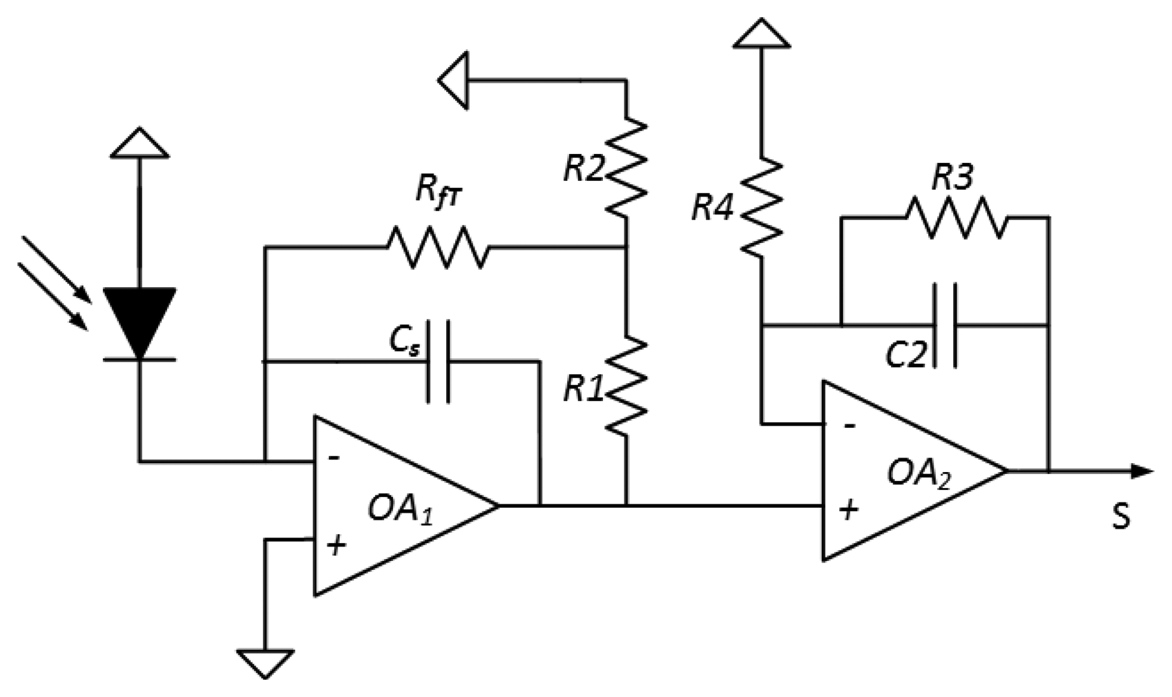
The system represented in Figure 5 includes an InGaAs PIN photodiode and a dual-stage circuit. The first stage is a tee-transimpedance amplifier topology [30–33], which transforms the photocurrent (current generated by the PD) into voltage. The most popular design approach to achieve high precision current-to-voltage conversion is the circuit composed of an operational amplifier network with a resistor in the feedback loop. In particular, the resistor tee-network still uses the fundamental concept of a resistive feedback loop to perform the current-to voltage conversion. In this circuit, R1 and R2 form a voltage divider which represents a fraction of the output voltage to RfT. Generally, R1 and R2 are small compared to RfT, thus, the effective feedback resistance Req is given by:
Note that highly effective feedback loop can be built relatively small values of resistances [34] which is useful in high-gain systems that would otherwise be limited by the effect of stray capacitance on RfT.
An additional benefit of the resistive tee-network is the reduction by a factor of (1 + R1/R2) in the output offset arising from the bias current requirement of the amplifier, but, at the expense of a proportional increase in the output error from the amplifier offset voltage [35]. The operational amplifier selected to implement the electronics are the low offset operational amplifier AD8639 from Analog Devices because provides high performance results.
The second stage post-amplifies and filters the output signals of the first stage with a very low cut-off frequency filter because the signal of interest is dc with slow variations over time due to the temperature of the cookware changes slowly. Usually, the transimpedance amplifier is connected to a low pass filter to further reduce the wideband noise in the rejected bandwidth. A single pole, low-pass filter improves the dynamic range of the transimpedance amplifier by a factor of 4 or 5 dB.
Finally, the output voltage, S, of the electronics is given by the following expression:
The cut-off frequency of the first stage is limited by the gain bandwidth product due to the high gain factor. The capacitor Cs is added for stability purposes. The cut-off frequency of the second stage has to be low enough in order to filter any kind of noise, but it should be as low as it is necessary to follow the evolution of the temperature over time. The cutoff frequency is around 16 Hz for C2 = 100 nF and R3 = 100 kΩ.
3.2. Experimental IR Temperature Control System for Induction Appliances
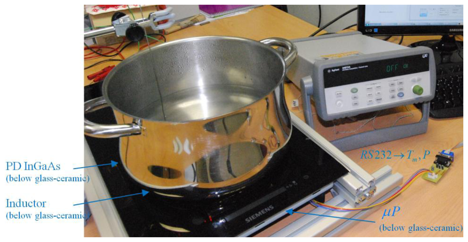
The experimental setup shown in Figure 6 has been built to test the performance of the preceding IR sensor under actual operational conditions of a domestic induction cooker.
3.2.1. Hardware Implementation
Figure 7 shows the block diagram of the temperature control system. The IR sensor is placed below the glass-ceramic slab. The temperature of the vessel is monitored by a thermocouple. The pan is heated up by the induction heating system which generates ringlike temperature distributions [6,8,36], where the hot spots are located in the middle positions of the ring.
In steady state at low power levels, the temperature distribution is more uniform than in heating transients. However, the temperature distribution is non-uniform at high power levels. To avoid this phenomenon in these kinds of heaters, the IR sensor and the thermocouple must be located at the same radial point. Radial point with maximum temperature has been selected.
The measurement procedure has been automated in order to acquire a large amount of experimental data. A data acquisition system (Agilent 34972A, Agilent Technologies Inc, SANTA CLARA, CA, USA) is used to store the information given by the thermocouple. Information relating to the glass-ceramic temperature and IR output voltage is obtained from the microprocessor. Microprocessor PIC24EP64GP206 of Microchip Technology (Chandler, AZ, USA) has been used, with 12-bit ADC and a sampling rate of 1 Ksps. A proportional-integral control is applied to control the output power level in order to reach the target temperature.
3.2.2. Software
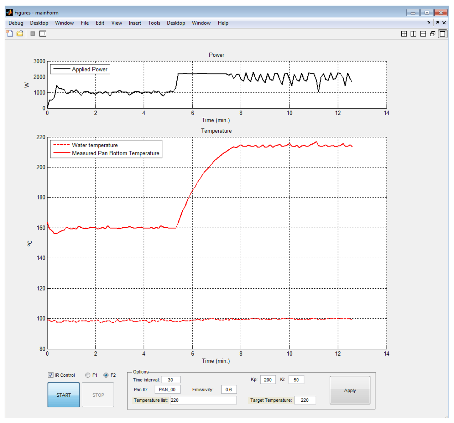
The main purpose of the software is to control the data acquisition process and to manage the acquired data. MATLAB is adopted as the programming language. The software of the monitoring system permits the configuration of the system and displays different data. Figure 8 shows the MATLAB user friendly interface module developed for displaying the electrical power, the temperature measurements and the estimation of the IR sensor temperature. The interface is suitable to select the parameters of the proportional-integral-controller and the target temperature. Afterwards, the data acquisition system runs automatically.
3.2.3. Calibration Procedure
The calibration of the IR sensor is required to obtain accurate temperature measurements in actual induction heating systems. Parameters a and q given in Equation (7) have been estimated from experimental measurements using a sample with constant emissivity in the wavelength band ranging between 1,200 and 2,600 nm.
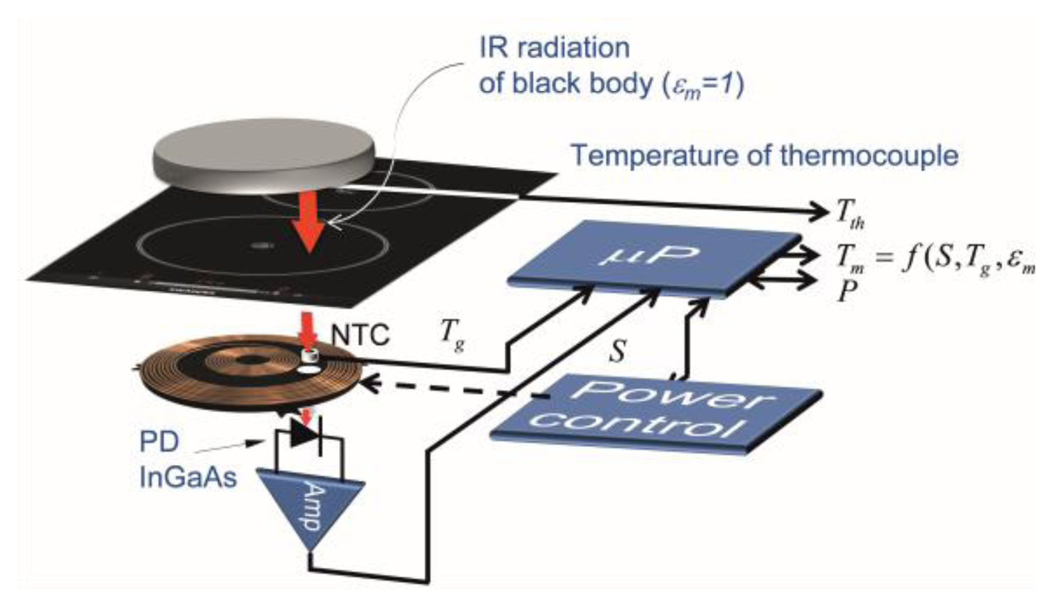
A black-body sample is heated by the induction heating system, and the temperature of the bottom of the sample, Tm, and the glass-ceramic, Tg, are registered simultaneously, as we can see in Figure 9. The temperature of the sample is varied from room temperature to 250 °C. Figure 10 shows the temperature of the bottom of the black-body measured with a thermocouple, Tth Temperature of the black-body bottom is stabilized over intervals of 250 s.
Figure 11a shows the measured output voltage, S, of sensor measured simultaneously with previous measurement. The black-body sample is built with a special multilayer structure deposited on a ferromagnetic steel disc using Physical Vapour Deposition (PVD) technique. The total reflectance is measured with a Vis-IR spectrophotometer equipped with an integrating sphere, shown in Figure 11b.
The temperature in the cookware, Tm, is calculated applying Equation (8). Figure 12 shows the calibration curve obtained from experimental measurement. A good fitting for the black-body is achieved.
After the calibration of the system was performed according to the previously described procedure, new measurements of the black-body in the temperature ranging from 50 to 250 °C are carried out.
Figure 13 shows the comparison between the IR sensor measured temperature, TIR, and the temperature measured by the thermocouple, Tth.
4. Results and Discussion
Several test and measurements are carried out in order to validate the reliability and accuracy of the experimental measurements as well as the applicability of IR sensor.
4.1. Response
First of all, the IR sensor applied to the domestic induction heating cooktop is tested at temperatures ranging from 60 to 250 °C was carried. In that case, a metal disk sample with emissivity εm = 0.6 acts as the induction load. The temperature of the metal disk sample, Tm, is measured by a thermocouple attached to its base.
Figure 14a shows temperature measured with the thermocouple, Tth, and the infrared sensor temperature, TIR, stabilized by the control. The maximum temperature error of 5 °C is obtained in the range between 60 and 250 °C whereas the average error of the measurement is around 1.5 °C. It should be noted that the proposed IR system provides accurate temperature measurement and power controlling below 60 °C.
In a real system, the emissivity of the cookware is not well-known. Cookwares have typical emissivities in the range from 0.2 to 0.9. Estimated errors for the IR sensor temperature assuming different sample emissivities are shown in Figure 15. The temperature is overestimated at low-emissivities whereas the system overestimates the temperature at high-emissivities. In conclusion, the maximum absolute error is around 20 °C when the emissivity of the cookware is not known.
As a consequence, accurate estimation of the emissivity of the cookware is required to achieve accurate temperature measurement for all types of cookware because, in that case, the temperature can be determined with a precision of within 5 °C, as shown in Figure 14b.
Determination or compensation of emissivity, in real time, can be performed in different ways. First, by multi-wavelength infrared thermometry technique [37–40], second, by a direct measurement of the total reflectance, and, finally, through the use of compensation techniques based on radiation exchange between surfaces [41–43].
4.2. Water Pre-Boiling and Boiling Point Temperature Control in an Induction Heating Hob
Although the efficiency of the power electronics is very high the waste of energy in the cooking process highly decreases the energy efficiency of induction cookers. Improvements in the energy efficiency during the cooking process could be therefore achieved by means of accurate pot temperature control. Control system [44] for the temperature of food during the cooking and automatic detection system of the boiling point [45,46] are also advantageous. For instance, pot temperature control ensures correct food cooking minimizing the cooking time as well as avoids the hazard to reach excessive temperatures, which can imply the burning of the food.
The relationship between the IR sensor temperature and water temperature depends on the boiling conditions determined, among others, by the type of container, volume of water, applied heater power. Figure 16 shows electrical power at same pre-boiling (97.5 °C) and boiling (100 °C) points under the operation conditions shown in Figure 8. At boiling point, the electrical power clearly increases, thus, the detection of the boiling point implies energy savings.
Both IR sensor and electrical power information could be very useful to define an automatic boiling point detection algorithm. The thermal transmission properties of the cookware at the boiling process can be extracted from the bottom cookware temperature and the maximum electrical power delivered by the cooktop. The thermal power flow can be derived from electrical the power consumption due to the high efficiency [47] of induction hobs.
5. Conclusions
In this work, a precise temperature control system based on IR thermometry has been presented. The theoretical analysis of the system includes an algorithm to discount glass-ceramic contribution from the total signal which allows us to obtain the temperature of the cookware with a maximum temperature error of 5 °C in the range between 60 and 250 °C for a known cookware emissivity.
A real-time feedback control of the temperature has been implemented by means of induction hob electrical power. A simple and necessary calibration procedure with a black-body sample is presented.
The accuracy of our model has been tested and confirmed with measurements performed with the proposed system. It has been proved that the IR sensor works properly to stabilize the temperature in the range from 60 to 250 °C in the cookware heats up by commercial domestic induction cookers. Table 1 shows main characteristics of the IR temperature control system.
The output signal levels of the proposed system exhibit a moderate dependence on the emissivity of the cookware. Then, it is necessary to know accurately the emissivity of the cookware in order to achieve accurate temperature measurements for all types of cookware. Future works will be oriented in this way, because, by estimating the emissivity of cookware, the temperature can be determined with a precision of within 5 °C.
Acknowledgments
This work was supported in part by the Spanish MINECO under Grant IPT-2011-1158-920000, in part by the Diputacion General de Aragon through the funding for the Photonics Technologies Group (GTF), and in part by the Bosch and Siemens Home Appliances Group.
Author Contributions
Study concept and design: Javier Lasobras, Rafael Alonso, Eduardo Imaz. Acquisition of data: Javier Lasobras. Analysis and interpretation of data: Javier Lasobras, Rafael Alonso, Claudio Carretero. Drafting of the manuscript: Javier Lasobras, Claudio Carretero. Critical revision of the manuscript for important intellectual content: Rafael Alonso, Claudio Carretero. Blackbody and samples development: Enrique Carretero.
Conflicts of Interest
The authors declare no conflict of interest.
References
- Acero, J.; Burdio, J.M.; Barragan, L.A.; Navarro, D.; Alonso, R.; Ramon, J.; Monterde, F.; Hernandez, P.; Llorente, S.; Garde, I. Domestic induction appliances. IEEE Ind. Appl. Mag. 2010, 16, 39–47. [Google Scholar]
- Moreland, W.C. The induction range: Its performance and its development problems. IEEE Trans. Ind. Appl. 1973, 9, 81–85. [Google Scholar]
- Peters, P.H. A portable cool-surface induction cooking appliance. IEEE Trans. Ind. Appl. 1974, 10, 814–822. [Google Scholar]
- Acero, J.; Carretero, C.; Lucia, O.; Alonso, R.; Burdio, J.M. Mutual impedance of small ring-type coils for multiwinding induction heating appliances. IEEE Trans. Power Electron. 2013, 28, 1025–1035. [Google Scholar]
- Acero, J.; Carretero, C.; Millan, I.; Lucia, O.; Alonso, R.; Burdio, J.M. Analysis and modeling of planar concentric windings forming adaptable-diameter burners for induction heating appliances. IEEE Trans. Power Electron. 2011, 26, 1546–1558. [Google Scholar]
- Carretero, C.; Lucia, O.; Acero, J.; Burdio, J.M. Computational modeling of two partly-coupled coils supplied by a double half-bridge resonant inverter for induction heating appliances. IEEE Trans. Ind. Electron. 2013, 60, 3092–3105. [Google Scholar]
- Egalon, J.; Caux, S.; Maussion, P.; Souley, M.; Pateau, O. Multiphase system for metal disc induction heating: Modeling and RMS current control. IEEE Trans. Ind. Appl. 2012, 48, 1692–1699. [Google Scholar]
- Fujita, H.; Uchida, N.; Ozaki, K. A new zone-control induction heating system using multiple inverter units applicable under mutual magnetic coupling conditions. IEEE Trans. Power Electron. 2011, 26, 2009–2017. [Google Scholar]
- Lucia, O.; Burdio, J.M.; Barragan, L.A.; Carretero, C.; Acero, J. Series resonant multiinverter with discontinuous-mode control for improved light-load operation. IEEE Trans. Ind. Electron. 2011, 58, 5163–5171. [Google Scholar]
- Pham, H.N.; Fujita, H.; Ozaki, K.; Uchida, N. Estimating method of heat distribution using 3-D resistance matrix for zone-control induction heating systems. IEEE Trans. Power Electron. 2012, 27, 3374–3382. [Google Scholar]
- Paesa, D.; Franco, C.; Llorente, S.; Lopez-Nicolas, G.; Sagues, C. Adaptive simmering control for domestic induction cookers. IEEE Trans. Ind. Appl. 2011, 47, 2257–2267. [Google Scholar]
- Paesa, D.; Llorente, S.; Sagues, C.; Aldana, O. Adaptive observers applied to pan temperature control of induction hobs. IEEE Trans. Ind. Appl. 2009, 45, 1116–1125. [Google Scholar]
- Franco, C.; Acero, J.; Alonso, R.; Sagues, C.; Paesa, D. Inductive sensor for temperature measurement in induction heating applications. IEEE Sens. J 2012, 12, 996–1003. [Google Scholar]
- Schäfer, T.; Schubert, M.; Hampel, U. Temperature Grid Sensor for the Measurement of Spatial Temperature Distributions at Object Surfaces. Sensors 2013, 13, 1593–1602. [Google Scholar]
- Has, U.; Wassilew, D. Temperature control for food in pots on cooking hobs. IEEE Trans. Ind. Electron. 1999, 46, 1030–1034. [Google Scholar]
- Joung, O.; Kim, Y. Application of an IR Thermographic Device for the Detection of a Simulated Defect in a Pipe. Sensors 2006, 6, 1199–1208. [Google Scholar]
- Kim, B.; Heo, Y.; Suh, Y.; Kim, Y. Detection of simulated defect using IR temperature sensors and one point heating. Sensors 2008, 8, 3345–3354. [Google Scholar]
- Alfaro, S.C.A.; Franco, F.D. Exploring infrared sensoring for real time welding defects monitoring in GTAW. Sensors 2010, 10, 5962–5974. [Google Scholar]
- Pujana, J.; del Campo, L.; Pérez-Sáez, R.B.; Tello, M.J.; Gallego, I.; Arrazola, P.J. Radiation thermometry applied to temperature measurement in the cutting process. Meas. Sci. Technol. 2007, 18, 3409–3416. [Google Scholar]
- Usamentiaga, R.; Molleda, J.; Garcia, D.F.; Granda, J.C.; Rendueles, J.L. Temperature measurement of molten pig iron with slag characterization and detection using infrared computer vision. IEEE Trans. Instrum. Meas. 2012, 61, 1149–1159. [Google Scholar]
- Usamentiaga, R.; Molleda, J.; Garcia, D.F.; Bulnes, F.G. Monitoring sintering burn-through point using infrared thermography. Sensors 2013, 13, 10287–10305. [Google Scholar]
- Saito, M.; Kikuchi, K. Infrared optical fiber sensors. Opt. Rev. 1997, 4, 527–538. [Google Scholar]
- Imaz, E.; Alonso, R.; Heras, C.; Carretero, E.; Salinas, I. IR sensor for temperature measurement in domestic induction heating systems. Proceeding of 38th Annual Conference on IEEE Industrial Electronics Society 2012, Montreal, QC, USA, 25–28 October 2012; pp. 3281–3286.
- Imaz, E.; Alonso, R.; Heras, C.; Salinas, I.; Carretero, E.; Carretero, C. Infrared thermometry system for temperature measurement in induction heating appliances. IEEE Trans. Ind. Electron. 2013, 61, 2622–2630. [Google Scholar]
- Gardon, R. The emissivity of transparent materials. J. Am. Ceram. Soc. 1956, 39, 278–287. [Google Scholar]
- McMahon, H.O. Thermal radiation from partially transparent reflecting bodies. J. Opt. Soc. Am. 1950, 40, 376–378. [Google Scholar]
- DeWitt, D.; Nutter, G. Theory and Practice of Radiation Thermometry, 5th ed.; Wiley: New York, NY, USA, 1988. [Google Scholar]
- Howell, J.R.; Siegel, R.; Menguc, M.P. Thermal Radiation Heat Transfer, 5th ed.; Taylor and Francis: New York, NY, USA, 2010. [Google Scholar]
- Modest, M. Radiative Heat Transfer, 2nd ed.; Academic Press: Waltham, MA, USA, 2003. [Google Scholar]
- Graeme, J.G. Photodiode Amplifiers: OP AMP Solutions; McGraw-Hill: New York, NY, USA, 1995. [Google Scholar]
- Gorostiza, E.M.; Lazaro, J.L.; Meca, F.J.; Salido, D.; Espinosa, F.; Pallares, L. Infrared sensor system for mobile-robot positioning in intelligent spaces. Sensors 2011, 11, 5416–5438. [Google Scholar]
- Hernandez, W.; de Vicente, J. Measurement uncertainty estimation of a robust photometer circuit. Sensors 2009, 9, 3149–3160. [Google Scholar]
- Martinez, M.A.; Andujar, J.M.; Enrique, J.M. A new and inexpensive pyranometer for the visible spectral range. Sensors 2009, 9, 4615–4634. [Google Scholar]
- Wright, P.; Ozanyan, K.B.; Carey, S.J.; McCann, H. Design of high-performance photodiode receivers for optical tomography. IEEE Sens. J. 2005, 5, 281–288. [Google Scholar]
- Patil, P.T.; Mukherjee, G.K.; Sharma, A.K.; Mudholkar, R.R. High-gain transimpedance amplifier (TIA) for night airglow photometer. Int. J. Electron. Eng. Res. 2009, 1, 109–116. [Google Scholar]
- Meng, L.; Cheng, K.W.E.; Chan, K.W. Systematic approach to high-power and energy-efficient industrial induction cooker system: Circuit design, control strategy, and prototype evaluation. IEEE Trans. Power Electron. 2011, 26, 3754–3765. [Google Scholar]
- Gardner, J.L.; Jones, T.P. Multi-wavelength radiation pyrometry where reflectance is measured to estimate emissivity. J. Phys. E: Sci. Instrum. 1980, 13, 306–310. [Google Scholar]
- Madura, H.; Kastek, M.; Piatkowski, T. Automatic compensation of emissivity in three-wavelenth pyrometers. Infrared Phys. Technol. 2007, 51, 1–8. [Google Scholar]
- Müller, B.; Renz, U. Development of a fast fiber-optic two-color pyrometer for the temperature measurement of surfaces with varying emissivities. Rev. Sci. Instrum. 2001, 72, 3366–3374. [Google Scholar]
- Wen, C.-D.; Chai, T.-Y. Examination of multispectral radiation thermometry using linear and log-linear emissivity models for aluminum alloys. Heat Mass Transf. 2011, 47, 847–856. [Google Scholar]
- Becker, H.B.; Wall, T.F. Effect of specular reflection of hemispherical surface pyrometer on emissivity measurement. J. Phys. E: Sci. Instrum. 1981, 14, 998–1001. [Google Scholar]
- Drury, M.D.; Perry, K.P.; Land, T. Pyrometers for surface temperature measurement. J. Iron Steel Inst. 1951, 169, 245–250. [Google Scholar]
- Bedford, R.E.; Ma, C.K.; Chu, Z.; Sun, Y. Calculation of the radiant characteristics of a plane diffuse surface covered by a specular hemisphere. J. Phys. E: Sci. Instrum. 1988, 21, 785–791. [Google Scholar]
- Charoenwiangnuea, P.; Boonyaroonate, I.; Po-ngam, S. The simple temperature control for the low cost, high efficiency and high power factor induction cooking. Proceedings of 9th International Conference on Electrical Engineering/Electronics, Computer, Telecommunications and Information Technology (ECTI-CON), Phetchaburi, Thailand, 16–18 May 2012; pp. 1–4.
- Terai, H.; Kobayashi, Y.; Nakamoto, S. Boiling point detector for surface cooking unit. IEEE Trans. Ind. Appl. 1984, 20, 956–960. [Google Scholar]
- Chen, B.; Zhong, C.; Yang, S.; Yan, M. The application of soft-sensor technology in measuring water boiling point. Proceedings of Chinese Control Conference, Hunan, China, 26–31 July 2007; pp. 372–376.
- Acero, J.; Carretero, C.; Alonso, R.; Burdio, J.M. Quantitative evaluation of induction efficiency in domestic induction heating applications. IEEE Trans. Mag. 2013, 49, 1382–1389. [Google Scholar]


| Parameter | Value | Units |
|---|---|---|
| Wavelength | 1,200–2,600 | nm |
| Power control | 0–2,200 | W |
| Temperature range | 60–250 | °C |
| Precision * | ±5 | °C |
| Time response | 10−3 | s |
| Microprocessor Microchip PIC24EP64GP206 | ||
| Sampling rate | 1 | Ksps |
| ADC | 12 | bits |
* Precision for a known cookware emissivity.
© 2014 by the authors; licensee MDPI, Basel, Switzerland. This article is an open access article distributed under the terms and conditions of the Creative Commons Attribution license ( http://creativecommons.org/licenses/by/3.0/).
Share and Cite
Lasobras, J.; Alonso, R.; Carretero, C.; Carretero, E.; Imaz, E. Infrared Sensor-Based Temperature Control for Domestic Induction Cooktops. Sensors 2014, 14, 5278-5295. https://doi.org/10.3390/s140305278
Lasobras J, Alonso R, Carretero C, Carretero E, Imaz E. Infrared Sensor-Based Temperature Control for Domestic Induction Cooktops. Sensors. 2014; 14(3):5278-5295. https://doi.org/10.3390/s140305278
Chicago/Turabian StyleLasobras, Javier, Rafael Alonso, Claudio Carretero, Enrique Carretero, and Eduardo Imaz. 2014. "Infrared Sensor-Based Temperature Control for Domestic Induction Cooktops" Sensors 14, no. 3: 5278-5295. https://doi.org/10.3390/s140305278