The Use of Accelerometers and Gyroscopes to Estimate Hip and Knee Angles on Gait Analysis

Abstract
: In this paper the performance of a sensor system, which has been developed to estimate hip and knee angles and the beginning of the gait phase, have been investigated. The sensor system consists of accelerometers and gyroscopes. A new algorithm was developed in order to avoid the error accumulation due to the gyroscopes drift and vibrations due to the ground contact at the beginning of the stance phase. The proposed algorithm have been tested and compared to some existing algorithms on over-ground walking trials with a commercial device for assisted gait. The results have shown the good accuracy of the angles estimation, also in high angle rate movement.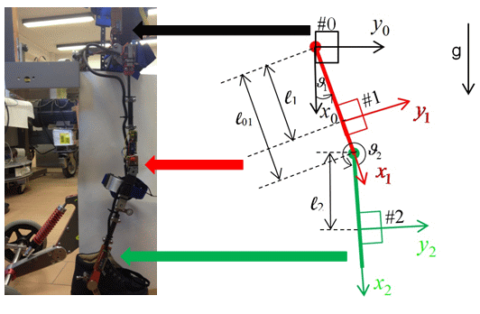
1. Introduction
Gait analysis can be very important to support the rehabilitation of patients with a motor impairment and the monitoring of the patient's healing progress. Indeed, gait analysis can provide a quantitative description of the gait cycle and then improve the standard observational analysis. In the rehabilitation of motor function, the physiotherapist normally evaluates the improvement of the patient and his motor learning just by the visual information of the movements or by measurement of the time for a task; on the other hand, quantitative evaluation of movements, with a measurement system, are commonly used in research works. Gait analysis has attracted an increasing amount of attention from researchers and clinicians since the 1970s. Using video cameras, gait analysis based on highly accurate computer-based force plates was established in the 1980s and was applied in specialized motion laboratories. An optical 3D motion analysis system with a camera was used in [1,2] to detect walking motion; gait analysis with these methods is expected to really improve rehabilitation training, since they are highly accurate; however, they are expensive, need sophisticated instrumentation and specialized personnel and can be used in a laboratory or a clinical environment; therefore, they are difficult to apply in daily life applications. However, this standard gait analysis is possible on specialized laboratories with expensive equipment and lengthy set-up and post-processing times. Moreover, limitations in terms of moving area and gait cycles have been observed for patients.
In order to mitigate these problems, alternative gait analysis methods based on wearable sensors were studied and have shown great perspectives in the past two decades. Indeed, the term wearable implies that such a system is portable, lightweight and safe. In order for such a device to be accessible for home use, additional requirements are that the wearable sensor systems have to be cheaper and easy to operate.
In recent years, wearable sensors, such as accelerometers and gyroscopes, have been used in the measurement of human motion and in gait analysis; these inertial sensors have the properties of lower cost, small size robustness, easiness of setting and a number of efficient algorithms that exists, providing the estimation of gait parameters. Therefore, they are suitable for clinical application. Placed on foot segments, inertial sensors can be used for gait parameter estimation [3,4]. However, by adding sensors on leg segments, more information, such as joint angles, can be obtained. Anyway, since the inertial sensors are known for their offset, which results in accumulated drift after numerical operation, such as integration, several methods have been developed and described in the literature trying to minimize or solve this problem. Morris et al. [5] ideied the beginning and the end of the walking cycle and made the signals at the beginning and at the end of the cycle equal. Sabatini et al. [6] proposed a method using quaternions for calculating body segment orientations from the angular velocity data of a body-mounted gyroscope; however, the proposed method uses the cyclic properties of gait to compensate for the drift. Another approach using quaternions is proposed in [7]: the initial orientations of the sensor units were estimated using acceleration data during an upright standing position, and the angular displacements were estimated using angular velocity data. An algorithm based on quaternion calculation was implemented for the orientation estimation of the sensor units, which were converted afterwards to the orientation of the body segments by a rotation matrix obtained from a calibration trail. Tong et al. [8] derived segment inclinations and the knee angle from segment angular velocities and applied a low-cut high-pass filter on the shank and thigh inclination angle signals, but removing low-frequency information. Favre et al. used acceleration data to compensate for the drift in the angular velocity data, but this compensation algorithm needs the dynamical acceleration to be negligible with respect to the gravitational acceleration [9].
Another method to estimate joint angles from measured accelerations is the estimation of angles between sensors and the vertical direction. These methods could became less accurate if the segment accelerations are as large as the gravity [10,11].
The accurate estimation of joint angles and the beginning of the stance phase allows the detection of the gait phases. Indeed, a normal walking gait cycle is divided into eight different gait phases, including initial contact, loading response, mid-stance, terminal stance, pre-swing, initial swing, mid-swing and terminal swing, and each phase is determined by the joint angles and gyros measurement [12].
A different approach was presented in [12], where each single gait phase was detected by means of gyroscopes and accelerometers; the former measured the angular velocity of each segment; the latter measured the inclination of the leg segment in every single gait cycle for periodic recalibration. An estimation algorithm was proposed to estimate segment orientations by integration of the angular velocity obtained from gyroscopes. Furthermore, Willemsen et al. [13] estimated joint angles without integration; the method is based on a comparison of signals from accelerometers mounted on adjacent segments of the leg. However, a low-pass filter is requested, therefore introducing a delay.
In many applications, the offset drift is solved by means of the Kalman filter. Cikajlo et al. proposed an algorithm where the Kalman filter is used to correct the shank inclination measured by the gyroscope [14]; in addition, the extended Kalman filter [15] and Gaussian particle filter [16] were also used to evaluate the hip angle in a walking cycle from the measurements of the wearable sensors, thus improving accuracy. Furthermore, a neural network [17] was applied for the estimation of ankle, knee and hip joint angles, obtaining good accuracy; however, this method needs training for individual settings before measurements in order to estimate with good accuracy.
Popovic et al. [18] proposed a new method for the estimation of absolute segment and joint angles during the gait; absolute angles of each segment were determined by band pass filtering the difference between signals from two accelerometers, while joint angles were evaluated by subtracting absolute angles of the neighboring segment. The offset drift was minimized with a Butterworth filter, and it can be additionally reduced if a high-pass filter is used in conjunction with the low-pass filter. This approach is similar to the method based on multi-rate complementary filtering theory developed in [19] for a navigation system. However, the method encounters an accuracy problem if the gait is slow; therefore, it is not acceptable for patients with a high level of disability. Another method of gait parameters recognition in real-time is proposed in [20], where the wearable system consists of a tri-axial accelerometer, and an autocorrelation procedure estimates the repeating characteristics over the gait periodic signal.
An interesting method was proposed by Watanabe et al. [21–23], where signals from the sensor attached on the foot were used in the gait length estimation, and joint angles were calculated as the integral of the difference between angular velocities measured from two gyroscopes attached on adjacent segments. The outputs of accelerometers are filtered with a Butterworth low-pass filter and used to measure inclination, and the offset drift problem was solved by the Kalman filter, used to estimate the error of the joint angle measured by gyroscopes from the differences between angles obtained by the gyroscopes and those by accelerometers.
A strategy to estimate hip and knee joint angles has been recently proposed in [24]. The proposed system is based only on accelerometers and gyroscopes measurements, and an exact solution of a second order kinematic equation gives the estimation of the hip and knee angles. In particular, the algorithm proposed in [24] was tested under walking on a short-distance pathway. Experiments showed a good performance of this algorithm, save for the time interval right after the contact of the foot with the ground, where there are vibrations.
In order to solve these issues in this paper, two methods are proposed to estimate gait parameters based on the complementary filter method [19]: the former merges the method proposed in [24] with the complementary filter method, whereas the latter merges the complementary filter method with the integrated gyro signals. The proposed algorithms estimate hip and knee angles on level ground walking tasks and the transition between the swing and stance phases, i.e., the instant of contact of the foot with the ground.
In the Section 2, we provide the methods for the hip and knee angles estimation and the complementary filter method used for the results comparison, whereas in Section 3, we present the sensor system. Furthermore, some experimental findings are shown in Section 4, and Section 5 deals with some conclusions.
2. Methods
2.1. Acceleration Propagation-Based Method (APB)
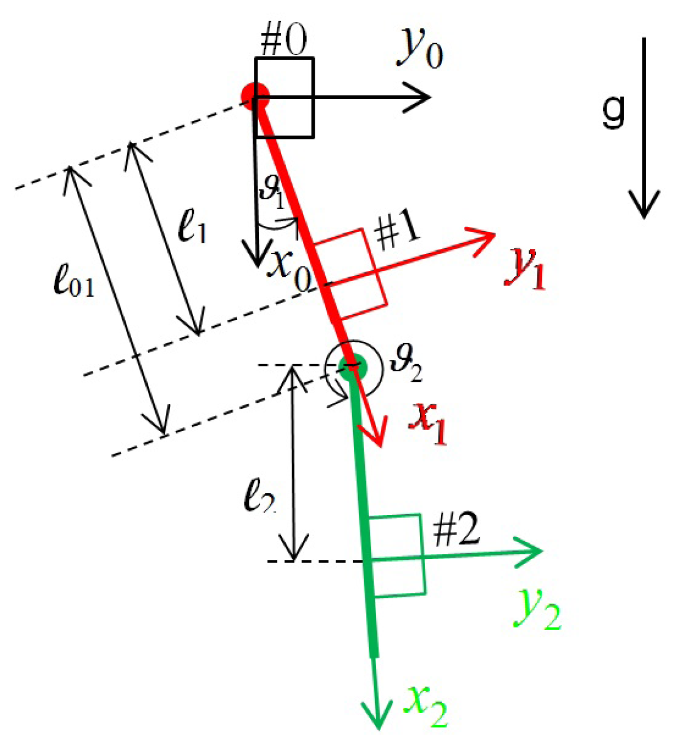
In this section, the acceleration propagation-based method originally proposed in [24] will be briefly reviewed. The sensor system is based only on low-cost inertial sensors, such as accelerometers and gyroscopes. The kinematic scheme, for each leg, is shown in Figure 1. In the same Figure, the location of the sensors is shown. Each group consist of one accelerometer and one gyro. A corresponding frame is located for each group of sensors and represents the position and orientation of the sensors.
A significant problem for the measurement of joint angles with gyroscopes is the error accumulation in the integral value, due to the pronounced drift. In order to avoid this drawback, the following second order kinematic model between two consecutive leg segment can be considered.
First, let us consider the kinematic relation expressing the position of the knee accelerometer, P1, with reference to that of the hip, P0:
As the measure from the i – th accelerometer can be expressed as:
Multiplying Equation (10) by and , it can be obtained, respectively:
In the same way for the second link, the position between the hip and ankle accelerometer is expressed by:
The two successive time differentiation of Equation (12) are:
As in the case of the first link, multiplying Equation (15) by and , it can be obtained, respectively:
Considering the kinematic relation (11), Equation (17) becomes:
The kinematic relations (18) are analogous to the Relations (11), except for the compensation terms, which depends on the difference (l1 — l01), namely the distance between the knee accelerometer and the origin of Frame 1. Therefore, if the knee accelerometer is put as l1 = l01, the system will become more robust, and the joint angle computation is a simple propagation of the same formula.
Note that a similar approach is proposed in [25], where the quaternion describing the orientation of the accelerometer is computed by the means of an optimization algorithm, but assuming the dynamic acceleration to be negligible compared to the static acceleration due to gravity.
2.2. Complementary Filter Method (CF)
The complementary filter is one of the most powerful and simple methods for the data fusion of different sources of information, which are complementary in a frequency domain [19]. Being a standard de facto, the CF approach will be compared to the acceleration propagation-based method (APB) on the angle estimation under walking on the short-distance pathway. Moreover, the others method proposed in this work are based on the complementary filter method (CF) and will be compared to it. For this reason, in the following, a brief introduction to the CF method will be given.
For every signal, P(s), and transfer function W(s), it is possible to write:
If W(s) has low-pass characteristics, 1 – W(s) has complementary high pass characteristics; then it is possible to obtain an approximation of the signal, P, by filtering two complementary sources of information:
In many applications, the high frequency approximation of the signal can be obtained by the integration of a velocity signal, which shows a low frequency drift phenomena. Then, Equation (20) can be written as:
The most simple implementation of the CF can be obtained starting from the low-pass filter:
In this application, the estimation of the position is based on measurements provided by accelerometers (Plow) and gyroscopes (υhigh). Indeed, accelerometers provide accurate information at a low frequency; however, gyroscopes show drift phenomena in the same frequency band; therefore, they are useful at higher frequencies.
2.3. Mixed Complementary Filter-APB (CF-APB)
The classical implementation of the CF requires the use of the accelerometer as an inclinometer, i.e., the dynamical acceleration must be negligible with respect to the gravitational one. Unfortunately, this hypotheses is also not true at low frequencies. For example, if the angle velocity is constant, a constant centrifugal acceleration disturbance will affect the radial component of the acceleration.
To solve this problem, a new complementary filter method has been introduced:
2.4. Intelligent Complementary Filter (ICF)
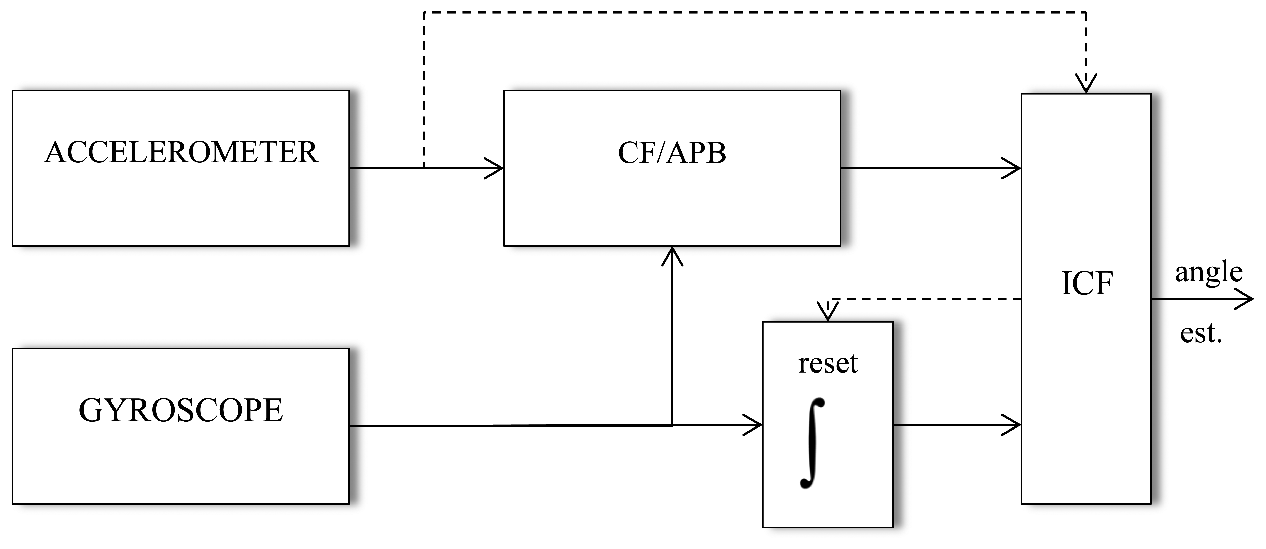
The APB algorithm, as well as the complementary filter method, as is shown in the next section, have an accurate performance in the walking tests, where there are not considerable fast variations of joint angles nor contacts of the foot with the ground, the latter bringing to oscillations of the position estimation for a short time interval due to the second order characteristic of the accelerometer. The proposed intelligent complementary filter (ICF) tries to solve this problem by using complementary filters with a rate limiter and the integrated signal from gyros blended together.
The general idea of the method proposed in this section is based on the fact that during oscillations, due to the contact, the integrated gyroscope signal is accurate enough. Then, the accelerometer signal, bringing oscillations in the time interval right after the contact of the foot with the ground, should not be considered in this circumstance, and the integrated gyroscope signal will be considered instead.
The scheme of the ICF estimation method is shown in the Figure 2. With reference to this Figure, the estimates of the joint angles is normally obtained by means of the CF or APB method. When the rate of estimation exceeds a given maximum value, the integrated gyroscopic signal is used instead. Finally, when the gap is over, the joint angles could be estimated again by means of the CF or APB. Other criteria could be considered in order to detect contact and switch, consequently, between methods. However, the proposed one gives the best experimental result. The value of the rate limiter is chosen as equal to the maximum value of the gyro sensor.
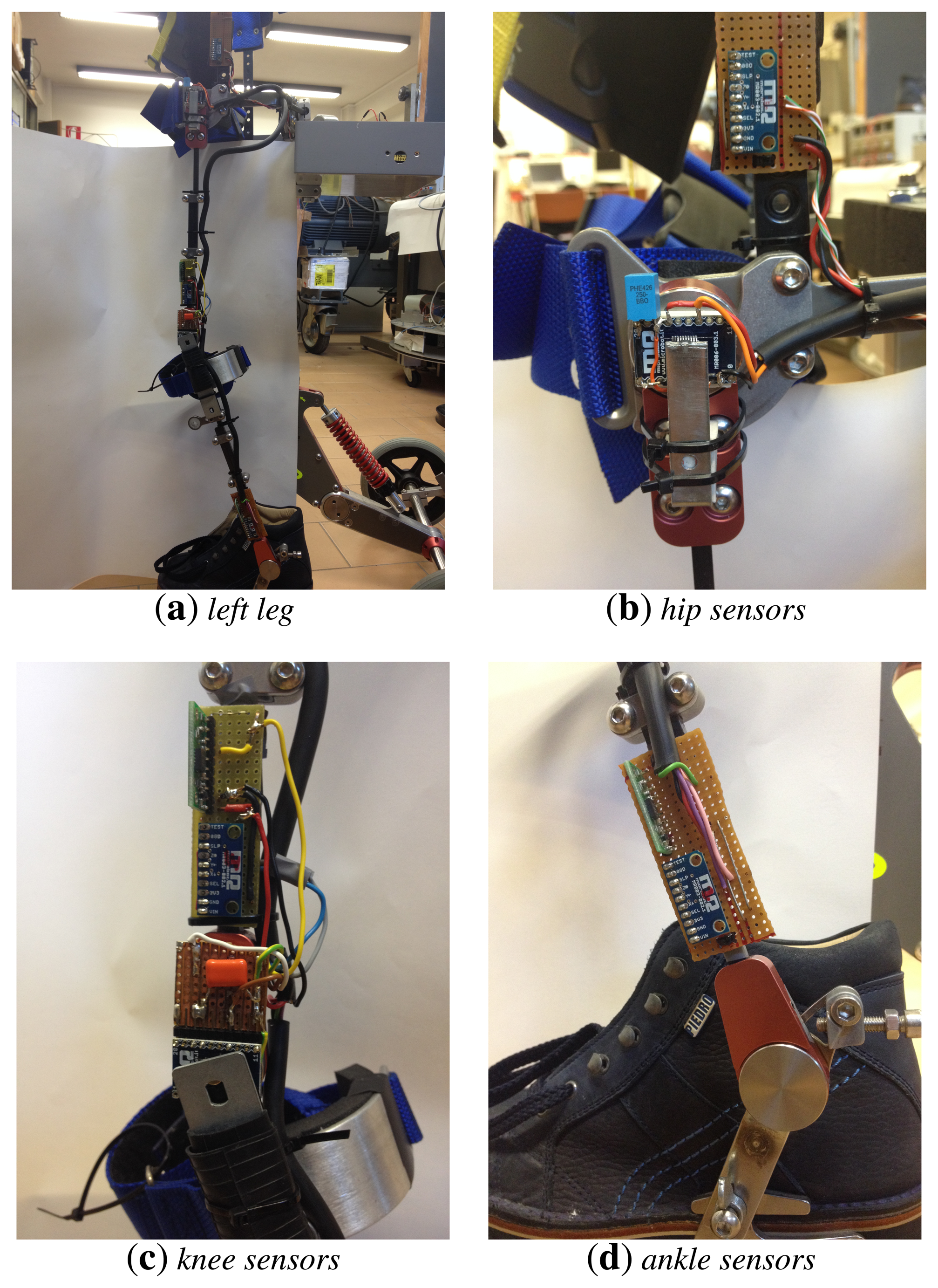
3. Sensor System
The sensor system consists of accelerometers and gyroscopes put near the knee and the ankle (see Figure 3); magnetic encoders were also put on the hip and knee joints in order to compare the results of the estimation algorithms to a reference angular measurement.
The experimental equipment is comprised of:
LPY510Al (ST), an analog, low-power dual-axis micro-machined gyroscope, capable of measuring the angular rate along pitch and yaw axes. It provides excellent temperature stability and high resolution. The gyroscope allows band limiting of the output rate response through the integrated low-pass filter.
MMA7361L (FreeScale), a capacitive low power, three-axis accelerometer, integrating a voltage regulator and a low-pass filter.
ARDUINO DUE, a microcontroller board based on the Atmel SAM3X8E ARM Cortex-M3 CPU, providing 54 digital input/output pins, 12 analog inputs (12 bits of resolution), an 84-MHz clock, 96 KBytes of SRAM, 512 KBytes of Flash memory for code.
AS5045 contactless magnetic rotary sensor for accurate angular measurement over a full turn. It is a system-on-chip, combining integrated hall elements, an analog front end and digital signal processing in a single device.
4. Results and Discussion
The proposed algorithm has been tested on angle measurements of the hip and knee of a commercial device for assisted gait: the NF-Walker [26]. The sensors were attached on the leg, as shown in the previous section.
The experiments performed have the main purpose of comparing the different ways of estimating hip and knee angles with direct angular measurement from encoders.
In addition, these algorithms are evaluated on an over-grounded walking trial. However, due to the limited laboratory size (therefore, the limited walking distance), this kind of measurement was restricted to only a few steps.
4.1. Experiment 1: Evaluation of the CF-APB Method
This experiment is performed to evaluate the performance of the mixed complementary filter-APB (CF-APB) algorithm on an over-ground walking trial.
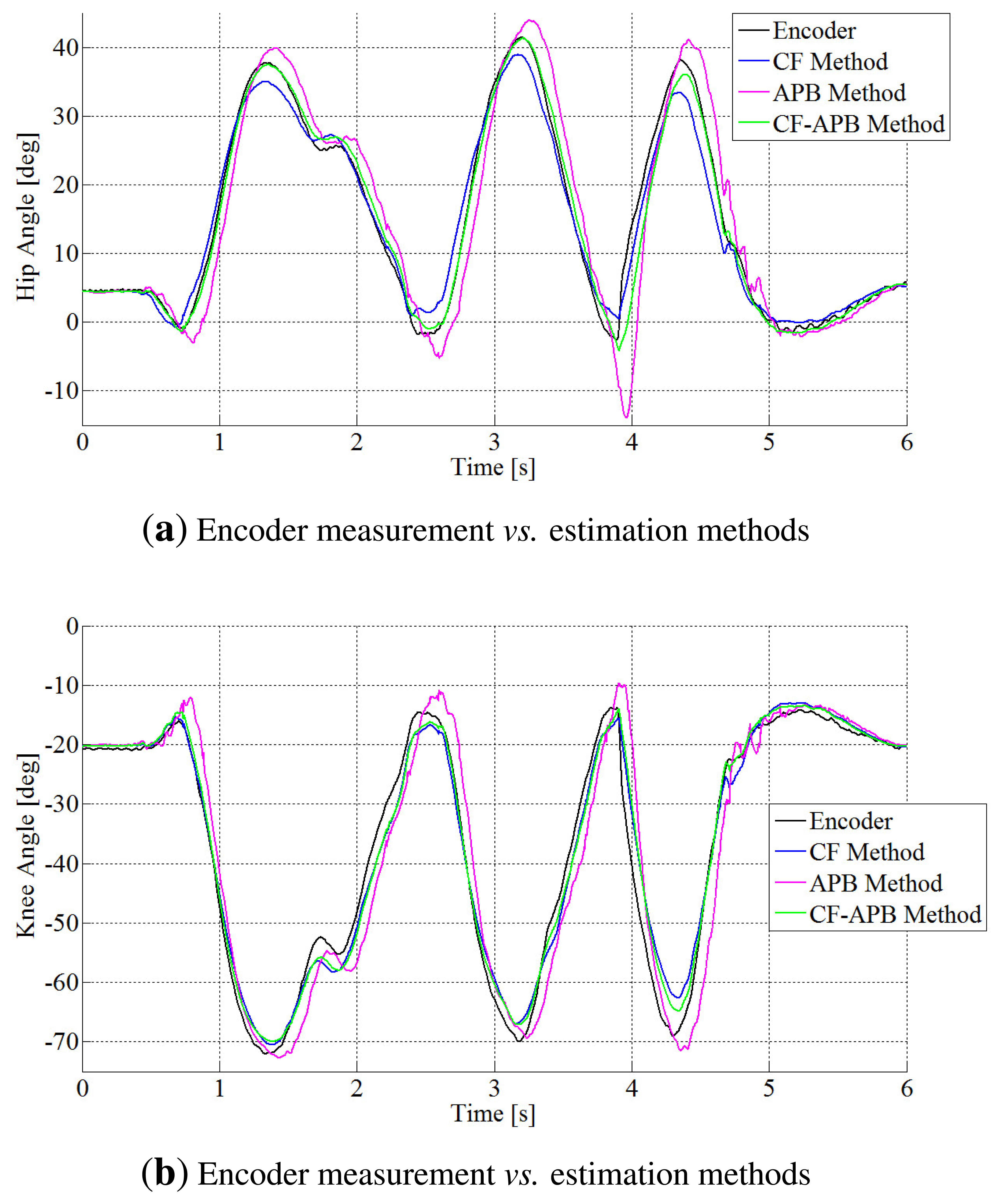
In the Figure 4, a comparison of the performances of the APB method with the classic CF method is shown, and the mixed complementary filtering approach (CF-APB), as well.
From this figure, it is pointed out that the APB algorithm, as well as the complementary filter method show good accuracy for the angle estimation, save for a time interval after the contact, where there are vibrations.
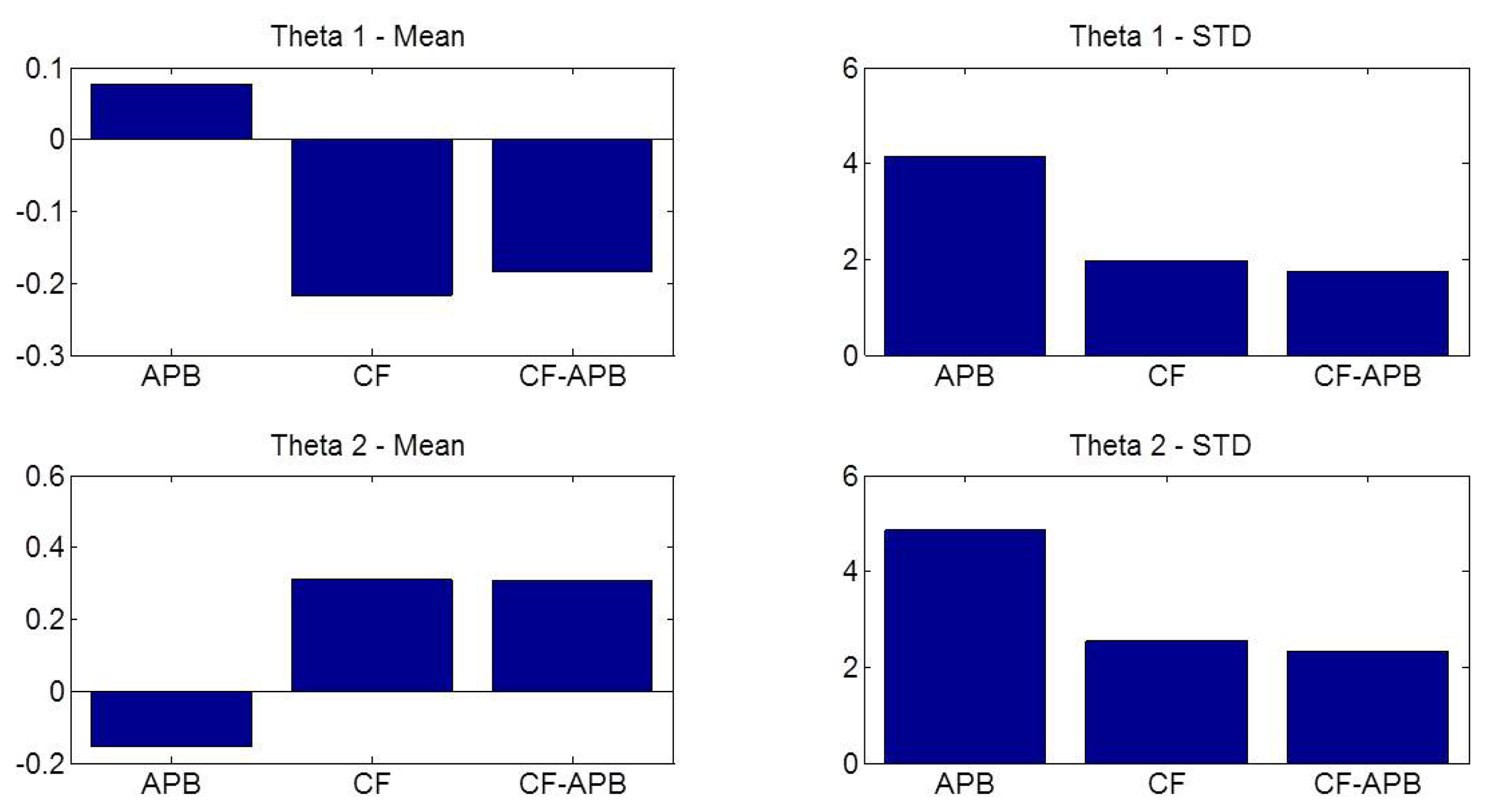
Finally, in Figure 5, it is pointed out, by means of a comparison between means and standard deviations, the improved performance of the CF-APB method for both hip and knee angle estimations. As we can see, comparing the APB and CF methods, the former presents a better value of means, whereas the latter produces a better value of the standard deviation. Therefore, the CF-APB algorithm, that is, both the previous algorithms bound together, presents a mixing of the advantages of both methods.
4.2. Experiment 2: Evaluation of the ICF Method
This experiment is performed to evaluate the performance of the intelligent complementary filter (ICF) algorithm on an over-ground walking trial.
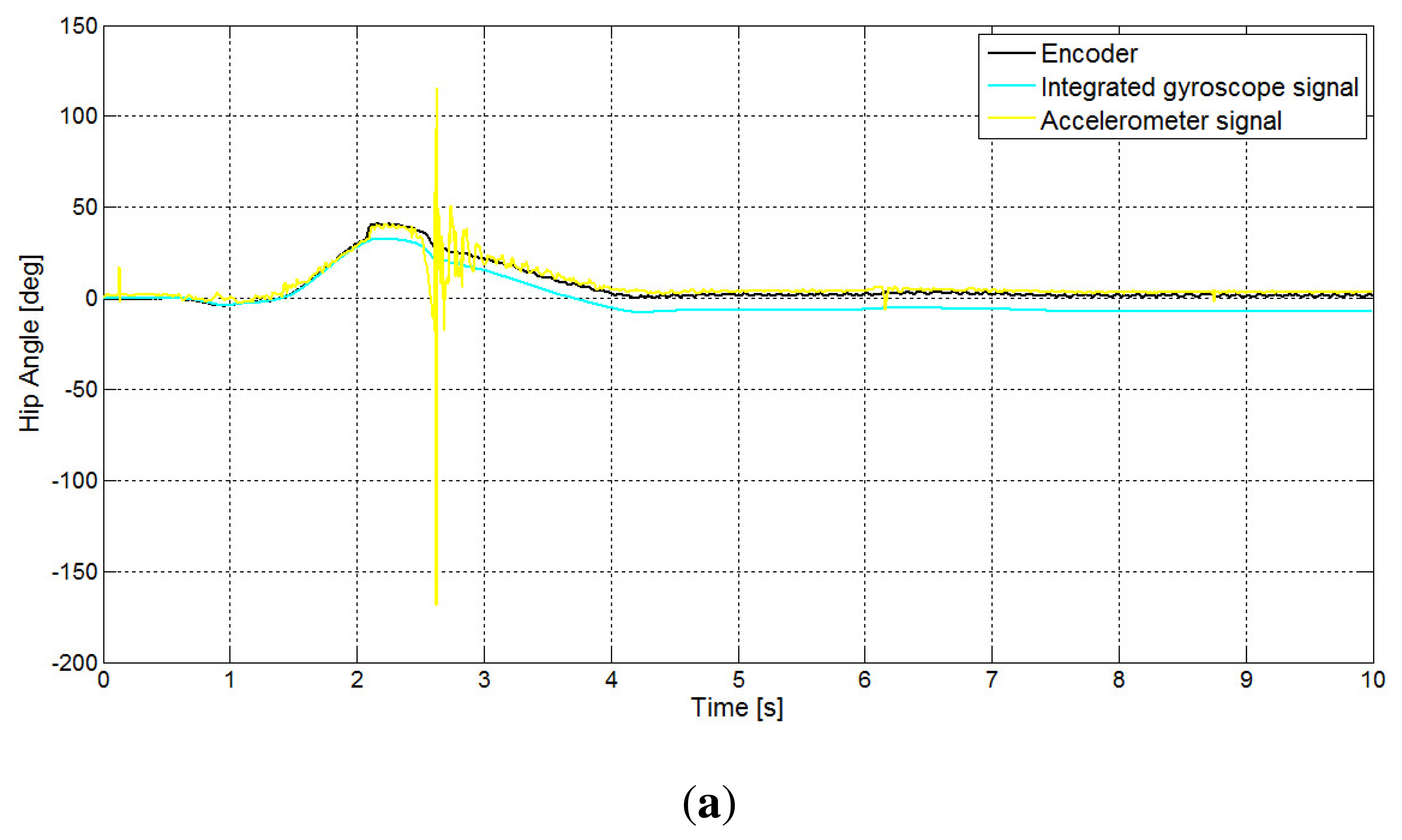
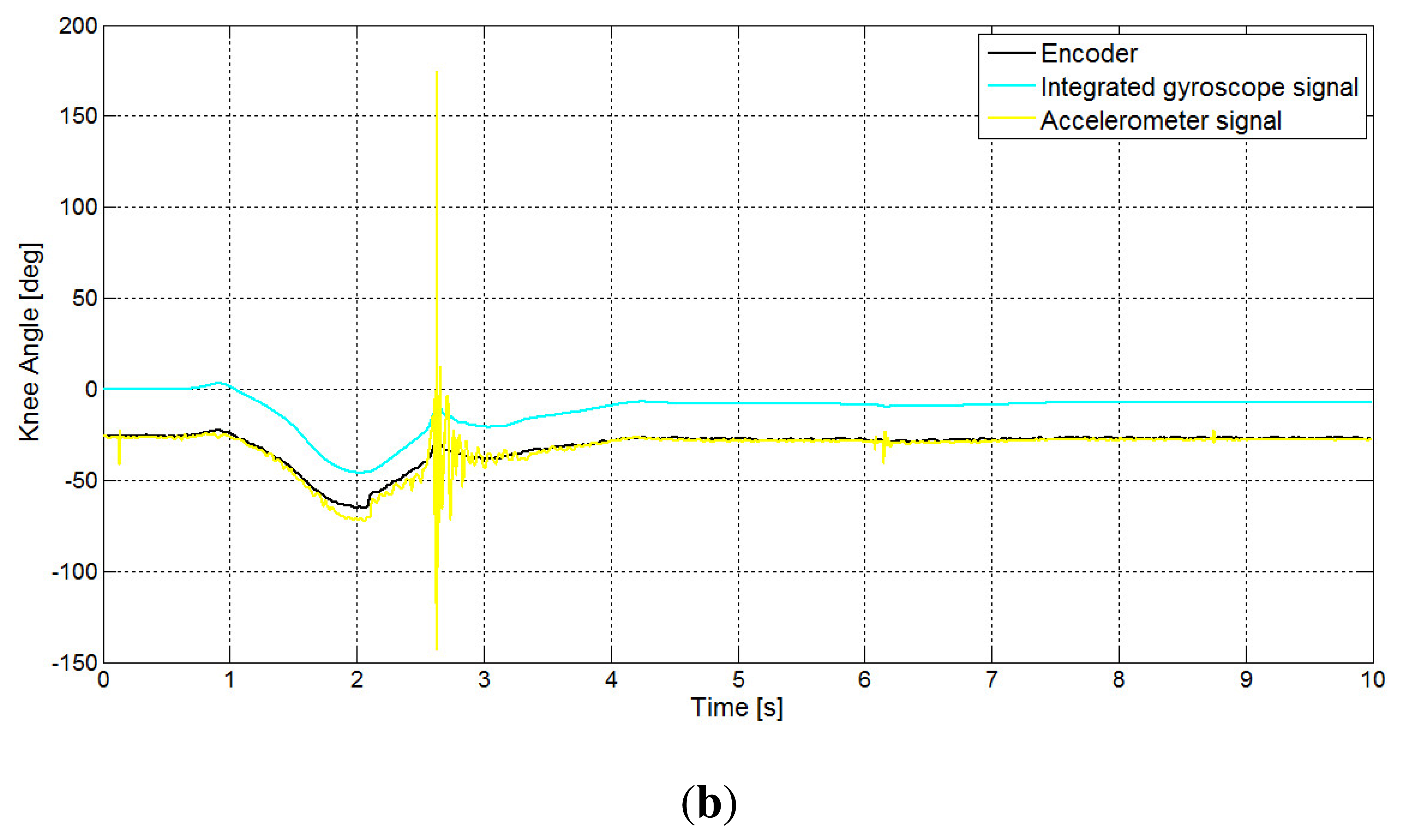
As already said, both the CF and ICF methods get information from a position signal obtained from the accelerometer and a second piece of position information obtained from the integral of the gyros. In Figure 6, these two signals are shown, with reference to the hip and knee angles. As is shown in the figure, the accelerometer-based position estimation signal fails to track the true position when contact of the foot with the ground occurs. On the other side, from the same signal, it is possible to easily detect the beginning of the stance phase, which is the instant where the foot comes into contact with the ground. The integral of the gyroscope, however, is not affected by the contact, but is affected by drift.
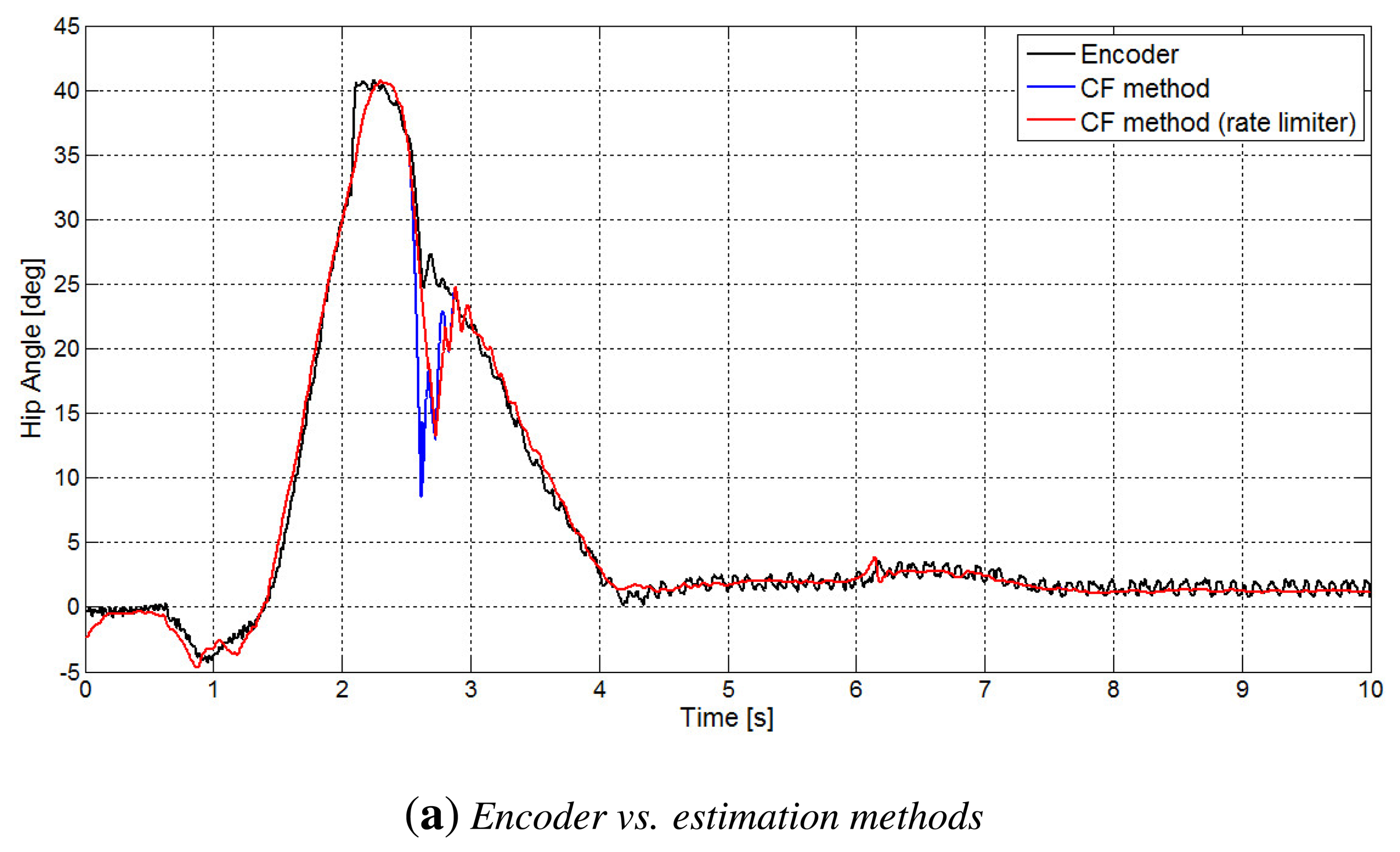
In the Figure 7, the behavior of the CF method for both hip and knee angles is shown. In particular, in Figure 7b–d is pointed out the occurrence of a consistent estimation error during the contact.
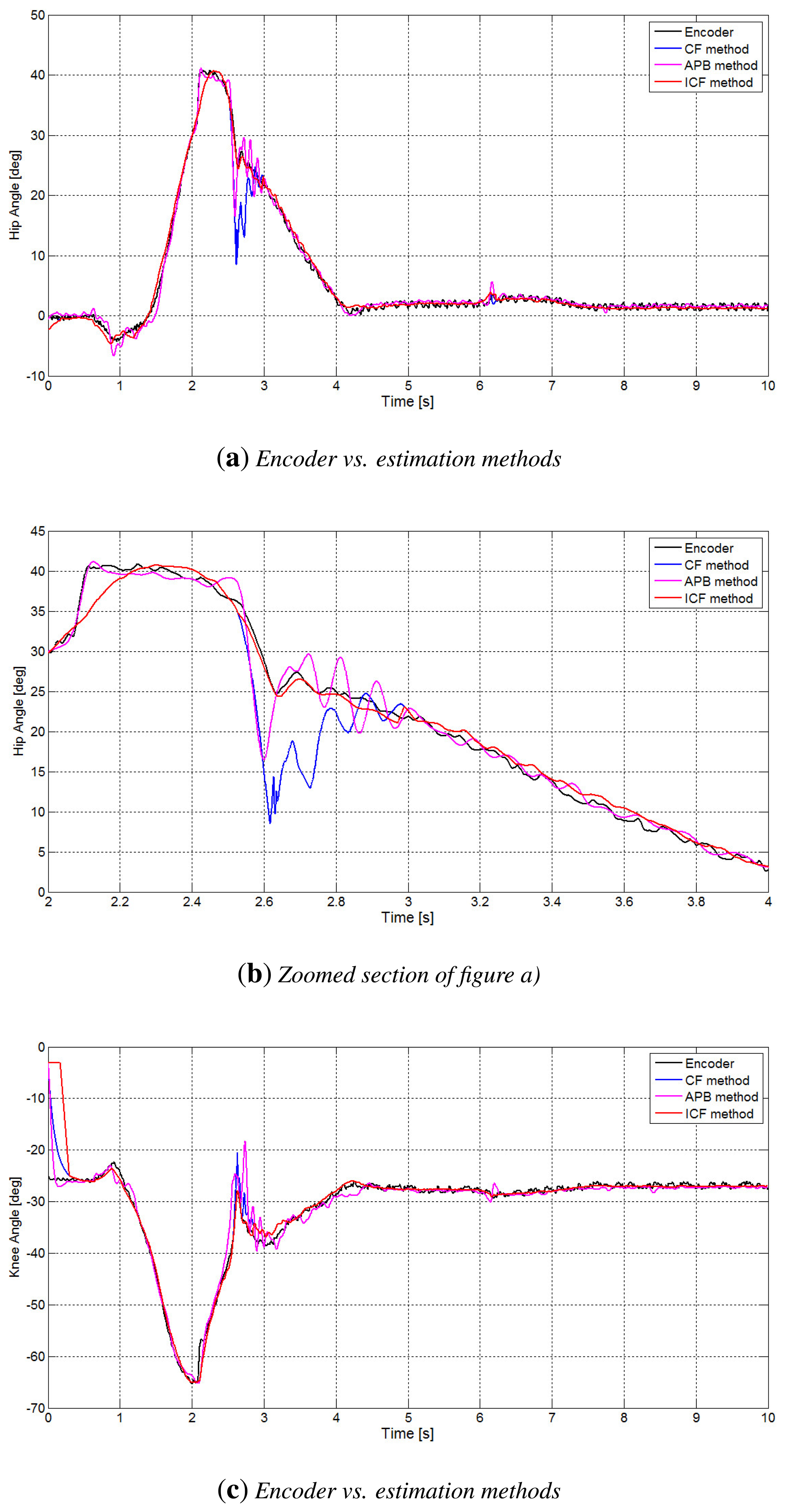
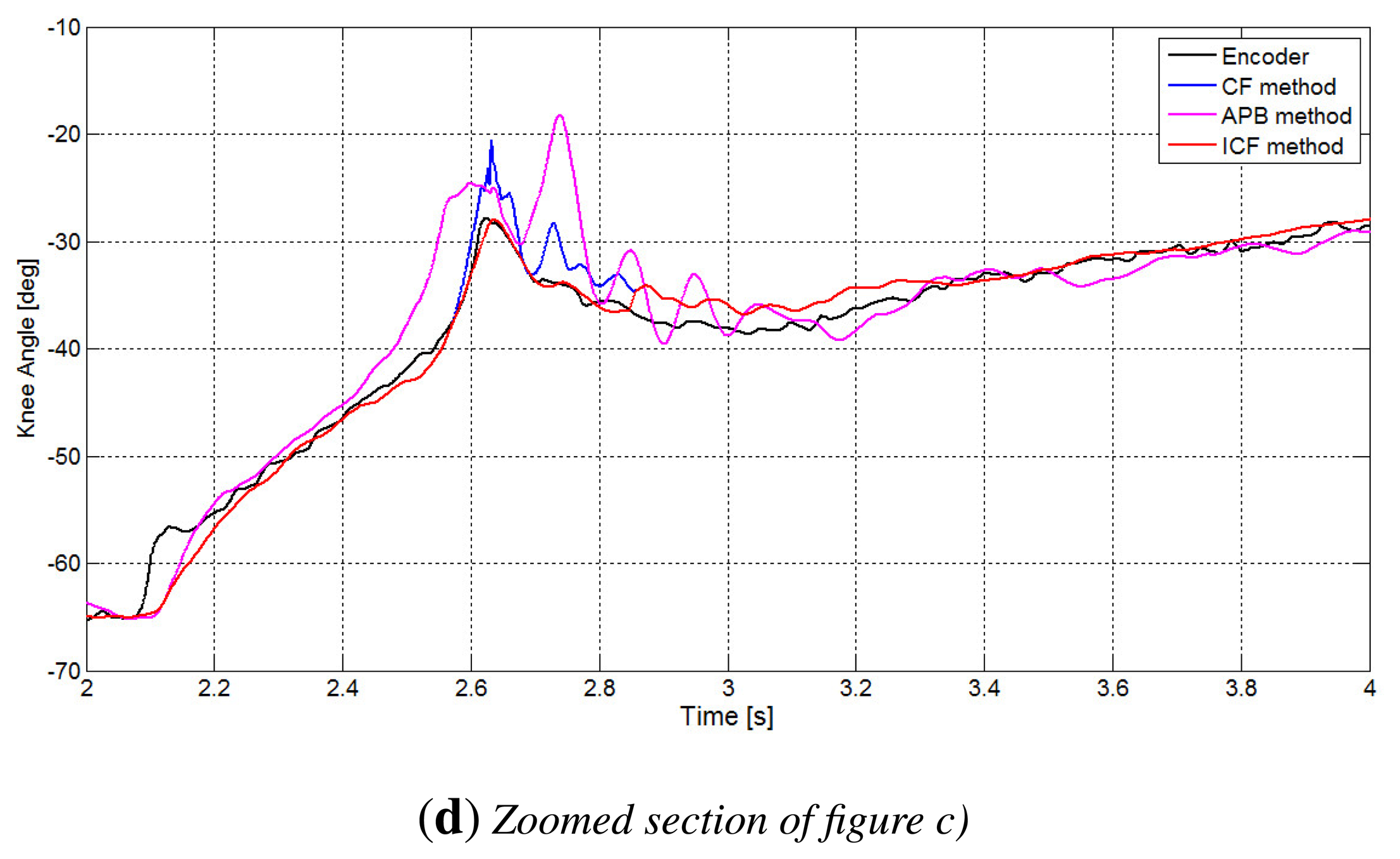
Finally, in Figure 8, there is a comparison of the performances of the APB, CF and ICF methods. In particular, in Figure 8b–d, the improvement of the performance of the ICF method is evident, especially in the time interval concerning the contact issues, where both the APB algorithm and the CF method present oscillations, and the estimation is not really accurate.
5. Conclusions
In this paper, a low-cost sensor system, based on accelerometer and gyroscope measurements, has been studied in order to estimate hip and knee angles during the rehabilitation and monitoring of patients.
The main purpose of the work is to avoid the significant problem of the error accumulation due to the offset drift caused by gyroscopes and the oscillations related to the time interval right after the contact of the foot with the ground, caused by the accelerometer.
In order to solve these problems, some algorithms have been proposed and experimentally evaluated and compared, estimating hip and knee angles during gait. In particular, as we can see from the experimental results, the acceleration propagation-based method (APB) and the complementary filter (CF) method have good performance, save for the time interval where the contact of the foot with the ground occurred. These problems were solved with the mixed complementary filter-ABP method (CF-APB) and the intelligent complementary filter method (ICF).
In addition, it is possible to use the trigger signals of accelerometers in order to detect the beginning of the stance phase, namely the initial contact of the foot with the ground.
The estimated gait parameters could be used in order to detect accurately gait phases, as is shown in [12]. The proposed algorithms have been tested on the angle measurement of the hip and knee of a commercial device for assisted gait, the NF-Walker.
Future developments of this algorithm will be the development of a mechanistic system for the walking assistance of motor-impaired child. In particular, hip and knee angle estimations, with both angular velocity and acceleration measurements and the detection of the beginning of stance phase will be shortly used to detect gait phase in a totally wearable system and, afterwards, to develop a proper control law to activate pneumatic muscles, put on the ortheses, in order to support the rehabilitation gait patterns.
Acknowledgments
This work was supported by the Italian Ministry of Education, University and Research, Research Project of National Interest: Robotics Collaborative and Cooperative (Ro.Co.Co.), 2011–2013.
Conflicts of Interest
The authors declare no conflicts of interest.
References
- Casadio, M.; Morasso, P.G.; Sanguineti, V. Direct measurement of ankle fness during quiet standing: Implications for control modeling and clinical application. Gait Posture 2005, 21, 410–424. [Google Scholar]
- Chacon-Murguia, M.I.; Sandoval-Rodriguez, R.; Arias-Enriquez, O. Human Gait Feature Extraction Including a Kinematic Analysis Toward Robotic Power Assistance. Int. J. Adv. Robot. Syst. 2012, 9, 68–76. [Google Scholar]
- Santhiranayagam, B.K.; Lai, D.; Shilton, A.; Begg, R.; Palaniswami, M. Regression Models for Estimation Gait Parameters Using Inertial Sensors. Proceedings of the 2011 Seventh International Conference on Intelligent Sensors, Sensor Networks & Information Processing (ISSNIP), Adelaide, Australia, 6–9 December 2011; pp. 46–51.
- Hung, T.N.; Suh, Y.S. Inertial Sensor-Based Two Feet Motion Tracking for Gait Analysis. Sensors 2013, 13, 5614–5629. [Google Scholar]
- Morris, J.R.W. Accelerometry—A technique for the measurement of human body movements. J. Biomech. 1973, 6, 729–736. [Google Scholar]
- Sabatini, A.M. Quaternion based attitude estimation algorithm applied to signals from body-mounted gyroscopes. Electron. Lett. 2004, 40, 584–586. [Google Scholar]
- Tadano, S.; Takeda, R.; Miyagawa, H. Three Dimensional Gait Analysis Using Wearable Acceleration and Gyro Sensors Based on Quaternion Calculations. Sensors 2013, 13, 9321–9343. [Google Scholar]
- Tong, K.; Granat, M.H. A practical gait analysis system using gyroscopes. Med. Eng. Phys. 1999, 21, 87–94. [Google Scholar]
- Favre, J.; Jolles, B.M.; Siegrist, O.; Aminian, K. Quaternion-based fusion of gyroscopes and accelerometers to improve 3D angle measurement. Electron. Lett. 2006, 42, 612–614. [Google Scholar]
- Dejnabadi, H.; Jolles, B.M.; Aminian, K. A New Approach to Accurate Measurement of Uniaxial Joint Angles Based on a Combination of Accelerometers and Gyroscopes. IEEE Trans. Biomed. Eng. 2005, 52, 1478–1484. [Google Scholar]
- Dejnabadi, H.; Jolles, B.M.; Casanova, E.; Fua, P.; Aminian, K. Estimation and visualization of sagittal kinematics of lower limbs orientation using body-fixed sensors. IEEE Trans. Biomed. Eng. 2006, 53, 1385–1393. [Google Scholar]
- Liu, T.; Inoue, Y.; Shibata, K. Development of a wearable sensor system for quantitative gait analysis. Measurement 2009, 42, 978–988. [Google Scholar]
- Willemsen, A.T.; van Alste, J.A.; Boom, H.B.K. Real-time gait assessment utilizing a new way of accelerometry. J. Biomech. 1990, 23, 859–863. [Google Scholar]
- Cikajlo, I.; Matjai, Z.; Bajd, T. Efficient FES triggering applying Kalman filter during sensory supported treadmill walking. J. Med. Eng. Technol. 2008, 32, 133–144. [Google Scholar]
- Dong, L.; Wu, J.; Bao, X. A Hybrid HMM/Kalman filter for tracking hip angle in gait cycle. IEICE Trans. Inf. Syst. 2006, 7, 2319–2323. [Google Scholar]
- Zhang, Z.; Huang, Z.; Wu, J. Ambulatory hip angle estimation using Gaussian particle filter. J. Signal Process. Syst. 2009, 58, 341–357. [Google Scholar]
- Findlow, A.; Goulermas, J.Y.; Nester, C.; Howard, D.; Kenney, L.P.J. Predicting lower limb joint kinematics using wearable motion sensors. Gait Posture 2008, 28, 120–126. [Google Scholar]
- Djuric-Jovicic, M.D.; Jovicic, N.S.; Popovic, D. Kinematics of Gait: New Method for Angle Estimation Based on Accelerometers. Sensors 2011, 11, 10571–10585. [Google Scholar]
- Oliveira, P.; Pascoal, A. Navigation Systems Design: An Application of Multi-Rate Flltering Theory. Proceedings of the IEEE OCEANS Conference and Exhibition on Engineering for Sustainable Use of the Oceans, Nice, France, 28 September–1 October 1998; pp. 1348–1353.
- Yang, C.C.; Hsu, Y.L.; Shih, K.S.; Lu, J.M. Real-Time Gait Cycle Parameter Recognition Using a Wearable Accelerometry System. Sensors 2011, 11, 7314–7326. [Google Scholar]
- Watanabe, T.; Saito, H.; Koike, E.; Nitta, K. A preliminary Test of Measurement of Joint Angles and Stride Length with Wireless Inertial Sensors for Wearable Gait Evaluation System. Comput. Intell. Neurosci. 2011. [Google Scholar] [CrossRef]
- Watanabe, T.; Saito, H. Tests of Wireless Wearable Sensor System in Joint Angle Measurement of Lower Limbs. Proceedings of the 2011 Annual International Conference of the IEEE Engineering in Medicine and Biology Society, Boston, MA, USA, 30 August–3 September 2011.
- Saito, H.; Watanabe, T.; Arifin, A. Ankle and Knee Joint Angle Measurements during Gait with Wearable Sensor System for Rehabilitation. IFMBE 2009, 25, 506–509. [Google Scholar]
- Alonge, F.; Cucco, E.; D'Ippolito, F. Use of accelerometers and gyros for hip and knee angle estimation. Proceedings of the IEEE International Conference on Mechatronics and Automation, Takamatsu, Japan, 4–7 August 2013; pp. 939–944.
- Madgwick, S.O.H.; Harrison, A.J.L; Vaidyanathan, R. Estimation of IMU and MARG orientation using a gradient descent algorithm. Proceedings of the 2011 IEEE International Conference on Rehabilitation Robotics (ICORR), Zurich, Switzerland, 29 June–1 July 2011; pp. 1–7.
- NF-Walker. Available online: http://madeformovement.com/products/nf-walker (accessed on 9 May 2014).


© 2014 by the authors; licensee MDPI, Basel, Switzerland. This article is an open access article distributed under the terms and conditions of the Creative Commons Attribution license ( http://creativecommons.org/licenses/by/3.0/).
Share and Cite
Alonge, F.; Cucco, E.; D'Ippolito, F.; Pulizzotto, A. The Use of Accelerometers and Gyroscopes to Estimate Hip and Knee Angles on Gait Analysis. Sensors 2014, 14, 8430-8446. https://doi.org/10.3390/s140508430
Alonge F, Cucco E, D'Ippolito F, Pulizzotto A. The Use of Accelerometers and Gyroscopes to Estimate Hip and Knee Angles on Gait Analysis. Sensors. 2014; 14(5):8430-8446. https://doi.org/10.3390/s140508430
Chicago/Turabian StyleAlonge, Francesco, Elisa Cucco, Filippo D'Ippolito, and Alessio Pulizzotto. 2014. "The Use of Accelerometers and Gyroscopes to Estimate Hip and Knee Angles on Gait Analysis" Sensors 14, no. 5: 8430-8446. https://doi.org/10.3390/s140508430