A CMOS Humidity Sensor for Passive RFID Sensing Applications


Abstract
: This paper presents a low-cost low-power CMOS humidity sensor for passive RFID sensing applications. The humidity sensing element is implemented in standard CMOS technology without any further post-processing, which results in low fabrication costs. The interface of this humidity sensor employs a PLL-based architecture transferring sensor signal processing from the voltage domain to the frequency domain. Therefore this architecture allows the use of a fully digital circuit, which can operate on ultra-low supply voltage and thus achieves low-power consumption. The proposed humidity sensor has been fabricated in the TSMC 0.18 μm CMOS process. The measurements show this humidity sensor exhibits excellent linearity and stability within the relative humidity range. The sensor interface circuit consumes only 1.05 μW at 0.5 V supply voltage and reduces it at least by an order of magnitude compared to previous designs.1. Introduction
Radio Frequency IDentification (RFID), as a wireless automatic identification technology, is widely applied in traffic management, logistics transportation, medicine management, food production, etc. [1]. Passive RFID tags offer several advantages such as battery-less operation, wireless communication, high flexibility, low cost and fast deployment, which all result in their extensive applications in commercial use [2]. The passive RFID tag uses the wireless energy from the RFID reader as its power supply. Hence, the power dissipation of the passive RFID tag, which determines the maximum reading distance of the RFID reader, is crucial for the design of passive RFID tags. Furthermore, limited by the rectifier efficiency, the internal circuits of passive RFID tags have to operate on a supply voltage which is always lower than 1 V. Recently, with the rapid developments of the Internet of Things and sensor technology, research on adding sensing functionality to RFID tags has become a hot topic [3–6]. These smart RFID sensing tags not only extend the fields of application of RFID, but also contribute to reduce the cost of RFID system fabrication. Therefore, the design of these sensors for passive RFID applications has to meet the requirements of low-voltage and low-power.
Humidity measurements are essential for a wide range of applications, including environment monitoring systems, process control systems, pharmaceutical and biomedical applications, food preservation, etc. [7]. Humidity sensors usually measure Relative Humidity (RH) rather than absolute humidity. Relative humidity is the ratio of the moisture level to the saturated moisture level at the same temperature and pressure and expressed as a percentage. Capacitance [8] and resistance [9] are the two main measured parameters and the majority of commercial humidity sensors are of the capacitive type, which can offer low power consumption and wide operating range. Furthermore, they requires less complex interface circuits compared with the resistive type.
Various materials, such as porous ceramics and hygroscopic polymers, are used as humidity-sensitive materials [10]. Because of its good moisture absorption and compatibility with integrated circuit (IC) fabrication technologies, polyimide is a good candidate for moisture sensing films in capacitive humidity sensors for both Micro-Electro-Mechanical System (MEMS) and Complementary-Metal-Oxide Semiconductor (CMOS) technologies [11,12]. The humidity sensor fabricated in CMOS technology can easily be integrated with the readout circuits on a single chip [13,14], which has several advantages including improved accuracy, reduced size and lower fabrication cost. Some capacitive humidity sensors based on CMOS technology have been reported [15–19]. However, the designs [15–18] all require some post-processing steps and the design in [19] uses materials and steps not commonly found in standard fabrication processes. All of these factors will undoubtedly increase the fabrication costs.
CMOS technology has been mainly developed for digital IC. Benefitting from technology scaling, digital IC achieves great improvements on speed, power dissipation, chip area, etc. However, analog IC is less scalable and suffers more when going to nanometer CMOS technology. Apart from the issues of matching and noise, the threshold voltage is reduced less remarkably compared to the power supply, resulting in a reduced voltage headroom for traditional analog amplitude-based sensor interfaces [20]. To cope with this challenge, a novel method transferring sensor signal processing from the traditional voltage domain to the frequency domain has been put forward in recent years [21,22]. This method allows the use of fully digital circuits rather than analog circuits, overcoming the limitation of the decreased voltage headroom. Hence the interface circuit with this approach can work with ultra-low supply voltages and is especially suitable for low power interface design.
The paper aims to present a low-cost low-power humidity sensor for RFID sensing applications. The rest of the paper is organized as follows: Section 2 presents a low-cost humidity sensor which is fabricated in standard CMOS technology without any further post-processing. Section 3 introduces the Phased-Locked Loop (PLL)-based sensor interface theory first and then illustrates the implementation of the fully-digital sensor interface in detail. The measurement results are presented and compared with previous designs in Section 4. Finally, some conclusions are drawn in Section 5.
2. Capacitive Humidity Sensing Element
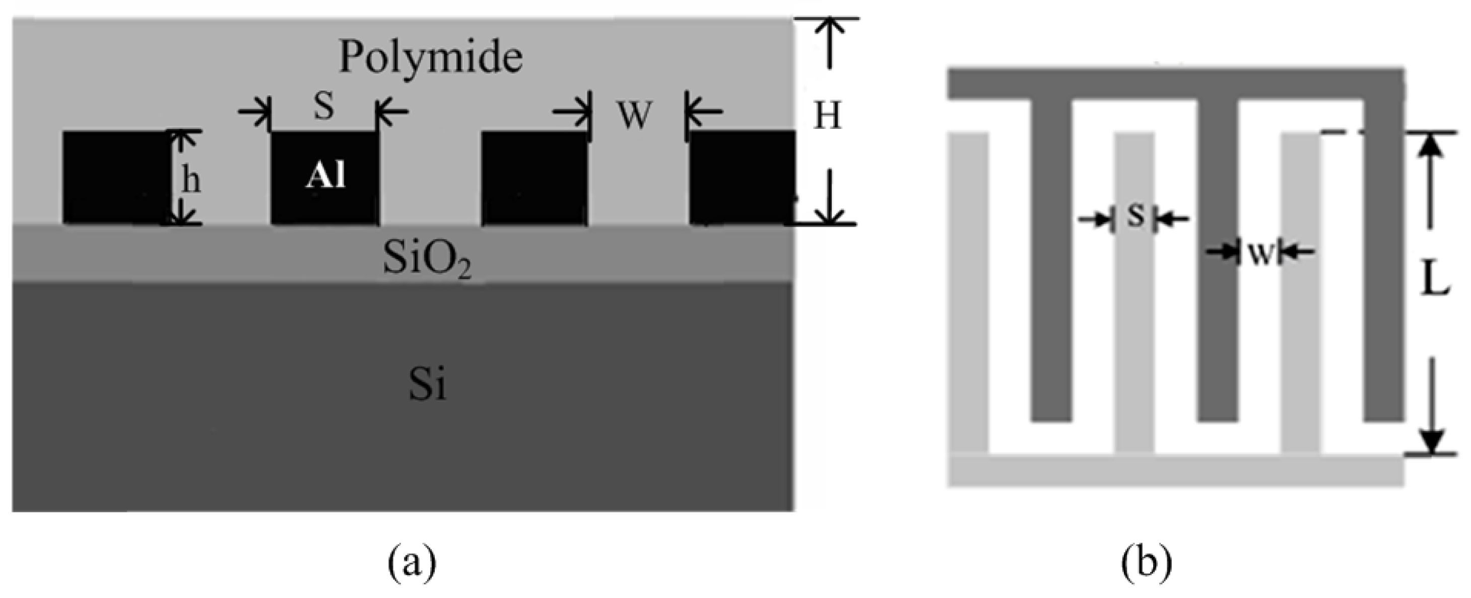
For a CMOS process, interdigitated top metal fingers, with polyimide filled into the finger gaps, can be utilized for capacitive humidity sensing. The line-to-line coupling capacitance of the top metal is sensitive to the dielectric constant of the filling material. Furthermore, due to the high precision of photolithography, such kinds of sensing structures are highly reproducible with less inter-die variations [23]. Figure 1a illustrates the structure of the proposed capacitive humidity sensor. It begins with the thermal growth of a thick SiO2 layer on the Si wafer. A thick aluminum layer is then deposited and patterned with standard optical lithography and wet etching over the SiO2 in order to form the interdigitated structure. The sensing film is polyimide that is coated on the interdigitated electrodes. In order for moist air to access the sensing film, there must be a large area of the polyimide exposed to the air. As is seen from Figure 1b, L is the length of aluminum electrodes, S is the width of each electrode, and W is the distance between adjacent electrodes. The thickness of the polyimide layer is H, which is generally larger than the metal thickness h.
The dielectric constant of the sensing film can be expressed by the Looyenga empirical equation [24] as follows:
For a N finger array sensor, the total sensor capacitance can be expressed as [27]:
The selection of the thickness of polyimide layer H has a great influence on the sensitivity and response time of the sensor. Generally, a humidity sensor with a thicker polyimide layer has better sensitivity and longer response time. Trading off the various factors, including sensitivity, response time, hysteresis performance and chip area, this work chooses N = 40, L = 200 μm, W = 2.5 μm, S = 2.5 μm, h = 1 μm and H ≈ 2 μm. The sensor capacitance can be evaluated in accordance with Equation (3) if the dielectric constant of the polyimide film εwet is given.
3. Humidity Sensor Interface
3.1. PLL-Based Sensor Interface Theory
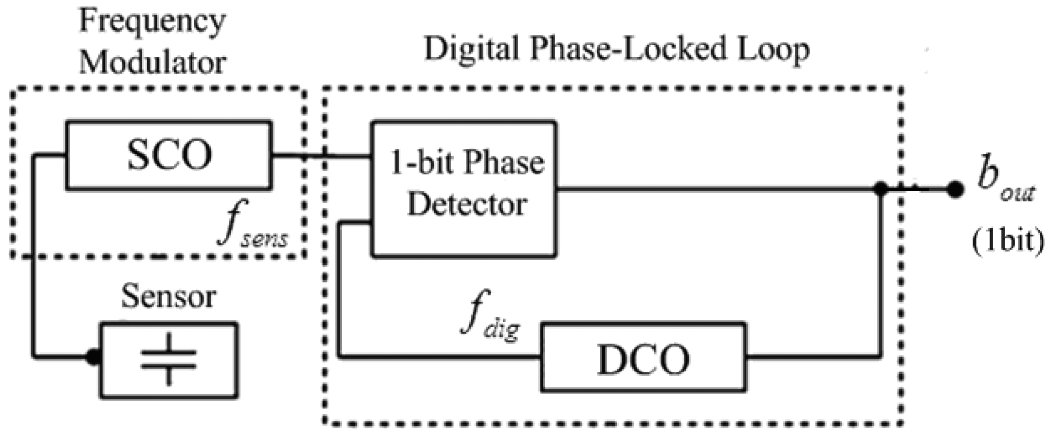
The architecture of PLL-based sensor interface, developed from Danneels [21], is shown in Figure 2. It consists of two main blocks: a frequency-modulating block, which converts the sensor information to the frequency domain, and a frequency-demodulating block, which converts the frequency to the digital domain, resulting in a complete sensor-to-digital flow. The frequency-modulating block consists of a Sensor-Controlled Oscillator (SCO) and directly converts the capacitive value of the sensor to a corresponding frequency fsens. The frequency-demodulating block is a digital first-order Bang-Bang-Phased-Locked-Loop (BBPLL), consisting of a single-bit phase detector and a Digitally-Controlled Oscillator (DCO). This BBPLL measures whether fsens leads or lags fdig (the frequency of the DCO) and hence the DCO is only steered by a single-bit signal bout. When the entire feedback loop is locked, fsens shifts between a maximum and minimum value which corresponds to the maximal and minimal value of the sensor. The average digital frequency fdig will correspond to the sensor frequency fsens. Therefore, the over-sampled output bout represents the digital value of the sensor value.
This architecture employs the BBPLL block, which has advantages ranging from low voltage capabilities, low power consumption, small chip area, and scalability to smaller technologies and robustness to process variation [28,29]. Another significant improvement of this architecture is the direct conversion from capacitive sensor signal to the frequency domain, avoiding any intermediate transformation of the capacitive information to the voltage domain.
3.2. Implementation of Fully-Digital Capacitive Sensor Interface
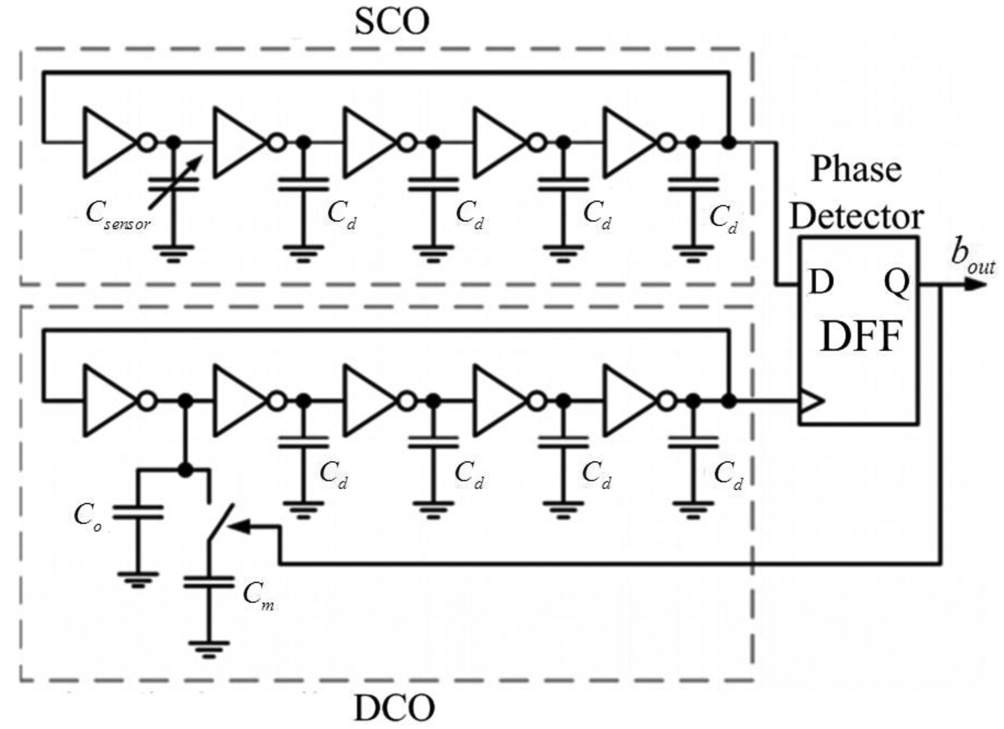
The implementation of the proposed fully-digital capacitive sensor interface is shown in Figure 3. Both the SCO and the DCO are implemented as five-stage inverter-based ring oscillators. The sensor capacitor Csensor acts as the variable load on a single stage of the SCO, thereby generating a sensor-controlled frequency fsens. The variable capacitive load on a single stage of the DCO consists of two capacitors, Co and Cm. The capacitor Co, designed equal to the quiescent value of Csensor, is always connected to the DCO. But the capacitor Cm, designed slightly larger than the maximum variation of Csensor, is swapped in or out of the DCO depending on the feedback from the single-bit phase-detector. Considering the issues of system linearity and process variation, Cm is normally designed as a programmable capacitor. The dummy load capacitor Cd at each stage should be carefully designed to be small enough for high resolution performance.
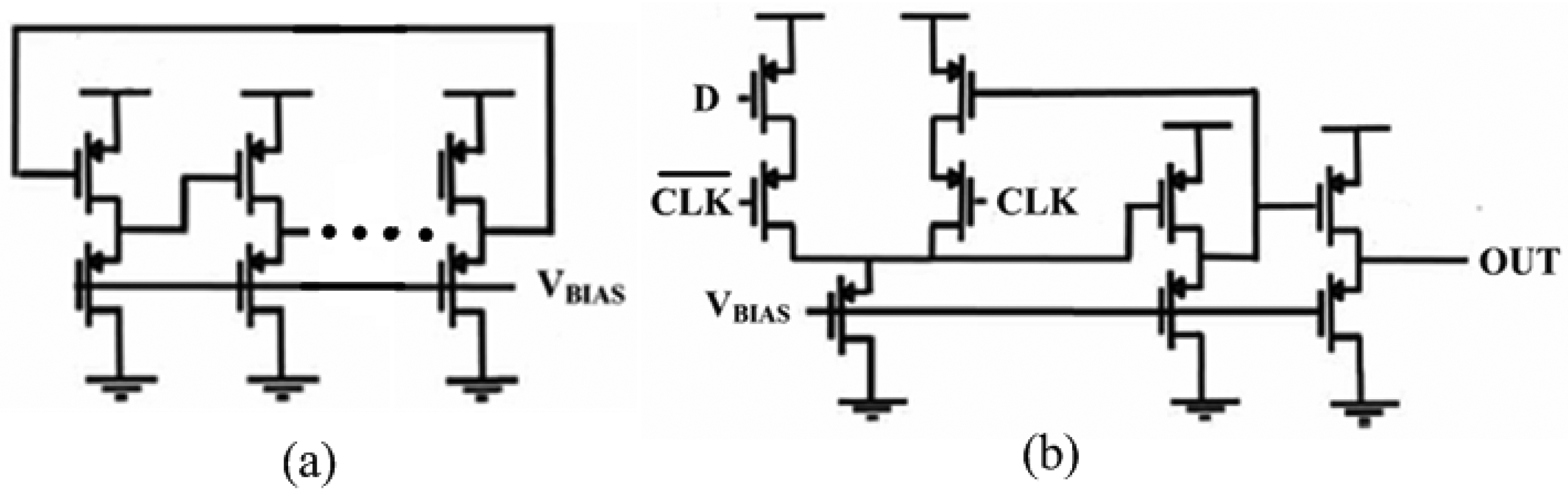
As shown in Figure 4, the ring oscillator employs simple inverters and the phase detector is only a D-Flip-Flop (DFF), which both are implemented in PMOS-only logic for increased gain and swing. As we discussed above, when the entire feedback loop is stable, the average values over time of fsens and fdig are equal, thus the two frequency controls of the SCO and DCO are correlated. Since both oscillators are implemented identically, the control of the SCO, the sensor value, is correlated to the control of the DCO, the single-bit output of the phase detector. Hence the value of the sensor is digitized in this single-bit DCO control signal (bout). In order to increase resolution, bout is over-sampled by taking its average duty cycle overtime [29].
For this work, the humidity sensor's capacitance varies from 5–6.5 pF within the relative humidity range. Hence the capacitors Co and Cm are selected as 5 pF and 2 pF, respectively. The dummy load capacitors (Co) at each stage are chosen to be 1 pF. Due to the fully digital architecture, the power supply of the interface is selected as 0.5 V, which is close to the process threshold voltage.
4. Measurement and Discussion
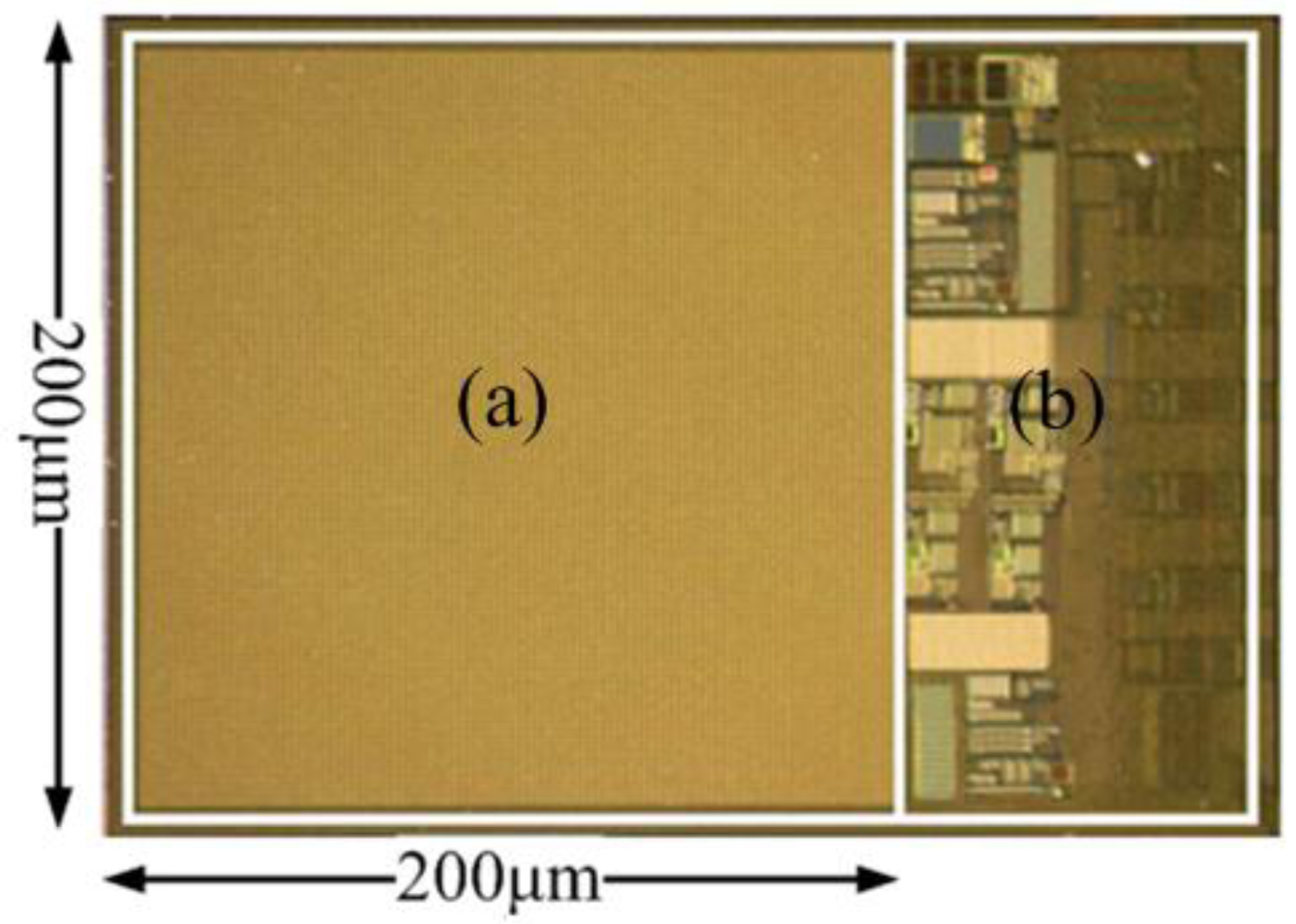
The proposed humidity sensor, fabricated in the Taiwan Semiconductor Manufacturing Company (TSMC) 0.18 μm 1P6M mixed-signal CMOS process, is shown in Figure 5. It includes two parts: the capacitive humidity sensor element (a) and the interface circuit (b), which cover 0.04 mm2 and 0.008 mm2, respectively. Two test humidity sensors, with 1 μm-thick and 2 μm-thick polyimide layers respectively, were measured in a Votsch VCL4003 (Votsch China, Taichang, China) temperature and climate test chamber.
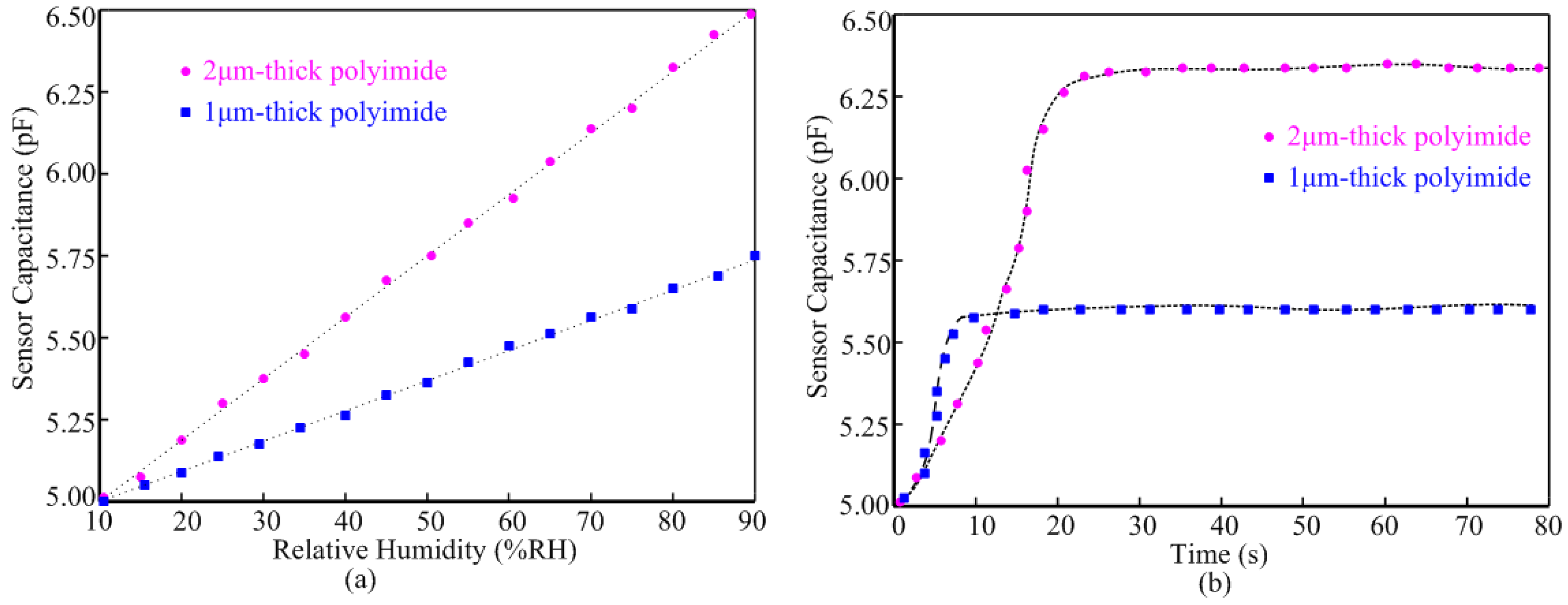
Figure 6 illustrates the polyimide thickness impacts on the performance of the humidity sensor at 25 °C. Figure 6a shows the sensor value with respect to the Relative Humidity (RH). Both sensors exhibit good linearity from 10%RH to 90%RH. The sensor with 2 μm-thick polyimide layer achieves 18.75 fF/%RH sensitivity, which is almost twice the sensitivity of the sensor with 1 μm-thick polyimide. The response time comparison of the two sensors is shown in Figure 6b. It was measured to 90% point of the final steady state capacitance after an abrupt relative humidity change from 10%RH to 80%RH at 25 °C. The response time of the sensor with 2 μm-thick polyimide layer is about 20 s, which is longer than the response time of the sensor with 1 μm-thick polyimide layer. For this work, the 20 s response time is acceptable and hence we coated the humidity sensor with 2 μm-thick polyimide for better sensitivity performance.
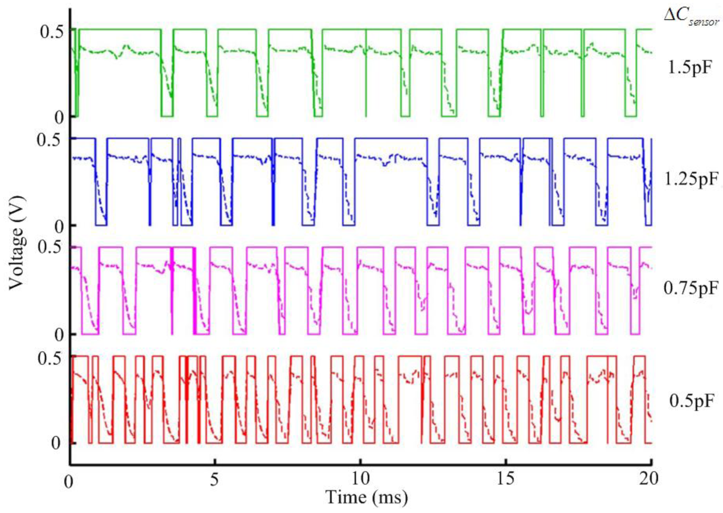
Figure 7 compares the different outputs corresponding to the different value change (ΔCsensor) of the humidity sensor with 2 μm-thick polyimide layer at 25 °C. The measured outputs (dotted line) and the digitized over-sampled outputs (solid line) are shown together. It is obvious that the average duty cycle of the output increases in proportion to the value of ΔCsensor.
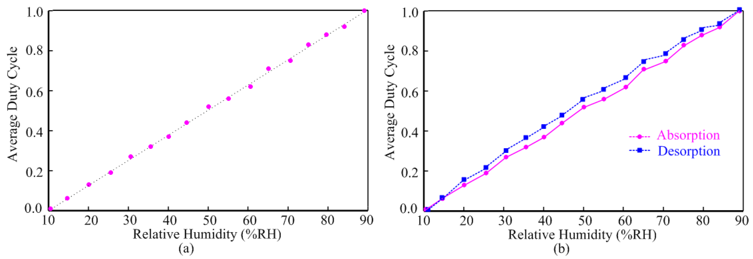
The measured sensitivity of the humidity sensor is shown in Figure 8. Figure 8a illustrates the average duty cycle responses of the output with respect to the relative humidity at 25 °C. Within the relative humidity range, this humidity sensor achieves high linearity performance at 25 °C. As it is shown in Figure 8b, the humidity sensor exhibits a reduced hysteresis. The maximum difference between the moisture absorption and desorption at the point 55%RH is not exceeding 7%.
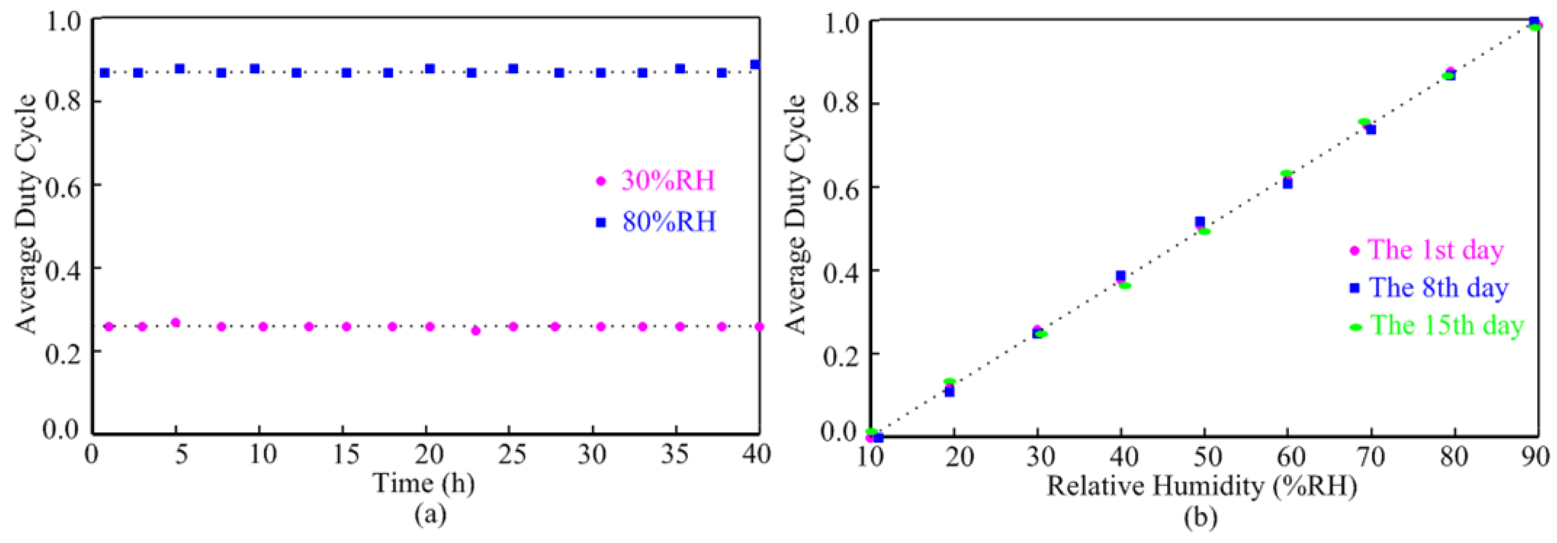
The stability measurement of the humidity sensor is given in Figure 9. The sensor, as shown in Figure 9a, was tested at the humidity of 30%RH and 80%RH for 40 h at 25 °C respectively and no obvious drift was observed. Figure 9b presents the test results of average duty cycle of interface outputs versus relative humidity on the 1st, 8th, 15th day so as to study the repeatability of the humidity sensor with time. It is obviously that the humidity sensor exhibits excellent repeatability.
Table 1 shows a comparison of the performance parameters of the proposed sensor interface with previous interface designs [30–33]. Owing to its simple architecture, the proposed sensor interface covers reduced chip area and can operate on 0.5 V ultra-low supply voltage. Despite the moderate Effective Number Of Bits (ENOB), this interface reduces power consumption at least one order of magnitude in respect with the previous designs.
5. Conclusions
The paper presents a integrated capacitive humidity sensor for RFID sensing applications. The humidity sensor is implemented in a standard CMOS process without any further post-processing, which results in low fabrication costs. The sensor interface, based on PLL architecture, transfers sensor signal processing from the traditional voltage domain to the frequency domain. It employs a fully-digital architecture and therefore can operate on an ultra-low supply voltage, which results in low power dissipation. The measurement results prove its excellent performance in the areas of linearity, stability, chip area and power dissipation. In particular the proposed sensor interface can work with 0.5 V supply voltage and consumes only 1.05 μW. Therefore this humidity sensor is particularly suitable for the mass-production of RFID sensing tags.
Acknowledgments
This work was supported by the National Natural Science Found of China for Distinguished Young Scholars (50925727), the National Defense Science and Technology Project of China (C1120110004, 9140A27020211DZ5102), the Key Grant Project of Chinese Ministry of Education (313018), the Key Science and Technology Project of Anhui Province of China (1301022036), and the Fundamental Research Funds for the Central Universities (2012HGCX0003). The authors would also like to thank TSMC semiconductor for its tape-out support and the RFID group in School of Electrical Engineering and Automation, Hefei University of Technology for their technical supports.
Conflicts of Interest
The authors declare no conflict of interest.
Reference
- Zuo, L.; He, Y.G.; Li, B.; Zhu, Y.Q.; Fang, G.F. Analysis and measurments of path loss effects for ultra high frequency radio-frequency identification in real environments. Acta Phys. Sinica 2013, 62, 4101–4110. [Google Scholar]
- Zuo, L.; He, Y.G.; Li, B.; Zhu, Y.Q.; Fang, G.F. Analysis and improvement for UHF RFID reading region in real enviorments. Acta Phys. Sinica 2012, 61, 4103–4111. [Google Scholar]
- Abad, E.; Palacio, F.; Nuin, M.; Zárate, A.; Juarros, A.; Gómez, J.M.; Marco, S. RFID smart tag for traceability and cold chain monitoring of foods: Demonstration in an intercontinental fresh fish logistic chain. J. Food Eng. 2009, 93, 394–399. [Google Scholar]
- Oprea, A.; Courbat, J.; Bârsan, N.; Briand, D.; de Rooij, N.F.; Weimar, U. Temperature, humidity and gas sensors integrated on plastic foil for low power applications. Sens. Actuators B Chem. 2009, 140, 227–232. [Google Scholar]
- Beriain, A.; Rebollo, I.; Fernandez, I.; Sevillano, J.F.; Berenguer, R. A passive UHF RFID pressure sensor tag with a 7.27 bit and 5.47 pj capacitive sensor interface. Proceedings of the 2012 IEEE International Microwave Symposium Digest (MTT), Montreal, Quebec, Canada, 17–22 June 2012; pp. 1–3.
- Cartasegna, D.; Conso, F.; Donida, A.; Grassi, M.; Picolli, L.; Rescio, G.; Regnicoli, G.F. Integrated microsystem with humidity, temperature and light sensors for monitoring the preservation conditions of food. Proceedings of the 2011 IEEE Sensor, Limerick, Ireland, 28–31 October 2011; pp. 1859–1862.
- Okada, C.T. Humidity Sensor: Types, Nanomaterials and Environmental Monitoring; Nova Science: New York, NY, USA, 2011; pp. 1–3. [Google Scholar]
- Kang, U.; Wise, K.D. A high-speed capacitive humidity sensor with on-chip thermal reset. IEEE Trans. Electron Devices 2000, 47, 702–710. [Google Scholar]
- Li, L.; Vilela, F.; Forgie, J.; Skabara, P.J.; Uttamchandani, D. Miniature humidity micro-sensor based on organic conductive polymer-poly (3, 4-ethylenedioxythiophene). Micro Nano Lett. IET 2009, 4, 84–87. [Google Scholar]
- Chen, Z.; Lu, C. Humidity sensors: A review of materials and mechanisms. Sens. Lett. 2005, 3, 274–295. [Google Scholar]
- Kim, J.H.; Hong, S.M.; Lee, J.S.; Moon, B.M.; Kim, K. High sensitivity capacitive humidity sensor with a novel polyimide design fabricated by MEMS technology. Proceedings of the 4th IEEE International Conference on Nano/Micro Engineered and Molecular Systems (NEMS), Kyoto, Japan, 5–8 January 2009; pp. 703–706.
- Nizhnik, O.; Higuchi, K.; Maenaka, K. A StandardCMOS HumiditySensor without Post-Processing. Sensors 2011, 11, 6197–6202. [Google Scholar]
- Okcan, B.; Akin, T. A low-power robust humidity sensor in a standard CMOS process. IEEE Trans. Electron Devices 2007, 54, 3071–3078. [Google Scholar]
- Boltshauser, T.; Azeredo, L.C.; Baltes, H. High sensitivity CMOS humidity sensors with on-chip absolute capacitance measurement system. Sens. Actuators B Chem. 1993, 15, 75–80. [Google Scholar]
- Gu, L.; Huang, Q.A.; Qin, M. A novel capacitive-type humidity sensor using CMOS fabrication technology. Sens. Actuators B Chem. 2004, 99, 491–498. [Google Scholar]
- Zhao, C.L.; Qin, M.; Huang, Q.A. A fully packaged CMOS interdigital capacitive humidity sensor with polysilicon heaters. IEEE Sens. 2011, 11, 2986–2992. [Google Scholar]
- Zhao, C.L.; Qin, M.; Li, W.H.; Huang, Q.A. Enhanced performance of a CMOS interdigital capacitive humidity sensor by graphene oxide. Proceedings of 16th International Solid-State Sensors, Actuators and Microsystems Conference (TRANSDUCERS), Kyoto, Japan, 5–9 June 2011; pp. 1954–1957.
- Dai, C.L.; Lu, D.H. Fabrication of a micro humidity sensor with polypyrrole using the CMOS process. Proceedings of the 5th IEEE International Conference on Nano/Micro Engineered and Molecular Systems, Nice, France, 20–23 January 2010; pp. 110–113.
- Nizhnik, O.; Higuchi, K.; Maenaka, K. Self-calibrated humidity sensor in CMOS without post-processing. Sensors 2012, 12, 226–232. [Google Scholar]
- Chatterjee, S.; Tsividis, Y.; Kinget, P. 0.5 V analog circuit techniques and their application in OTA and filter design. IEEE J. Solid-State Circuits 2005, 40, 2373–2387. [Google Scholar]
- Danneels, H.; Piette, F.; de Smedt, V.; Dehaene, W.; Gielen, G. A novel PLL-based frequency-to-digital conversion mechanism for sensor interfaces. Sens. Actuators A Phys. 2011, 172, 220–227. [Google Scholar]
- Danneels, H.; Piette, F.; Gielen, G. A novel PLL-based sensor interface for resistive pressure sensors. Procedia Eng. 2010, 5, 62–65. [Google Scholar]
- Laconte, J.; Wilmart, V.; Raskin, J.P.; Flandre, D. Capacitive humidity sensor using a polyimide sensing film. Proceedings of 2003 Symposium on Design, Test, Integration and Packaging of MEMS/MOEMS, Cannes, France, 25–27 April 2003; pp. 223–228.
- Looyenga, H. Dielectric constants of heterogeneous mixtures. Physica 1965, 31, 401–406. [Google Scholar]
- Schubert, P.J.; Nevin, J.H. A polyimide-based capacitive humidity sensor. IEEE Trans. Electron Devices 1985, 32, 1220–1223. [Google Scholar]
- Gevorgian, S.S.; Martinsson, T.; Linner, P.L.; Kollberg, E.L. CAD models for multilayered substrate interdigital capacitors. IEEE Trans. Microw. Theory Tech. 1996, 44, 896–904. [Google Scholar]
- Dai, C.L. A capacitive humidity sensor integrated with micro heater and ring oscillator circuit fabricated by CMOS–MEMS technique. Sens. Actuators B: Chem. 2007, 122, 375–380. [Google Scholar]
- Da Dalt, N. A design-oriented study of the nonlinear dynamics of digital bang-bang PLLs. IEEE Trans. Circuits Syst. I Regul. Pap. 2005, 52, 21–31. [Google Scholar]
- Van Rethy, J.; Danneels, H.; Gielen, G. Performance Analysis of Energy-Efficient BBPLL-Based Sensor-to-Digital Converters. IEEE Trans. Circuits Syst. I Regul. Pap. 2013, 11, 1881–1886. [Google Scholar]
- Bracke, W.; Merken, P.; Puers, R.; van Hoof, C. Ultra-low-power interface chip for autonomous capacitive sensor systems. IEEE Trans. Circuits Syst. I Regul. Pap. 2007, 54, 130–140. [Google Scholar]
- Shin, D.Y; Lee, H.; Kim, S. A delta-sigma interface circuit for capacitive sensors with an automatically calibrated zero point. IEEE Trans. Circuits Syst. II Express Briefs 2011, 58, 90–94. [Google Scholar]
- Tan, Z.; Daamen, R.; Humbert, A.; Ponomarev, Y.V.; Chae, Y.; Pertijs, M.A. A 1.2-V 8.3-nJ CMOS Humidity Sensor for RFID Applications. IEEE J. Solid State Circuits 2013, 48, 2469–2477. [Google Scholar]
- Nizza, N.; Dei, M.; Butti, F.; Bruschi, P. A low-power interface for capacitive sensors with PWM output and intrinsic low pass characteristic. IEEE Trans. Circuits Syst. I Regul. Pap. 2013, 60, 1419–1431. [Google Scholar]


© 2014 by the authors; licensee MDPI, Basel, Switzerland. This article is an open access article distributed under the terms and conditions of the Creative Commons Attribution license ( http://creativecommons.org/licenses/by/3.0/).
Share and Cite
Deng, F.; He, Y.; Zhang, C.; Feng, W. A CMOS Humidity Sensor for Passive RFID Sensing Applications. Sensors 2014, 14, 8728-8739. https://doi.org/10.3390/s140508728
Deng F, He Y, Zhang C, Feng W. A CMOS Humidity Sensor for Passive RFID Sensing Applications. Sensors. 2014; 14(5):8728-8739. https://doi.org/10.3390/s140508728
Chicago/Turabian StyleDeng, Fangming, Yigang He, Chaolong Zhang, and Wei Feng. 2014. "A CMOS Humidity Sensor for Passive RFID Sensing Applications" Sensors 14, no. 5: 8728-8739. https://doi.org/10.3390/s140508728