1. Introduction
The global commercial unmanned aerial vehicle (UAV) market has shown considerable growth [
1], gradually embracing a wide range of applications. Irrespective of the underlying application (media and entertainment, energy, government, agriculture, search and rescue (SAR), environment, etc.), the majority of common UAV operations involve image and video acquisition, maneuvering, navigational attitude, routing to predefined waypoints, landing and failsafe features, which are processed and fulfilled through the standard flight controller systems. Nevertheless, in order to address a broader range of applications, one has to migrate to integrated processing add-ons that would carry out on demand, on-board, collaborative or autonomous functions, towards an intelligent UAV functionality. Increasing the computational potential of the UAV does not solely address computationally demanding tasks, but transforms the UAV into a potential decision operating system that can take control of its own flight and perform optimized missions.
The significance of UAV autonomy and processing power is demonstrated in several applications including technical infrastructure inspection [
2,
3,
4,
5,
6], indoor navigation using simultaneous localization and mapping [
7,
8,
9,
10], obstacle avoidance [
11,
12,
13,
14], terrain reconstruction [
15,
16,
17], and real-time environmental monitoring [
18,
19]. The flexibility, human safety, cost effectiveness and ease of use facilitates the usage of UAVs to support humanitarian actions in disaster situations [
20,
21]. The identification and rescue of potential victims in the shortest possible time constitutes the main objective of search and rescue operations [
22,
23].
In the current study, we address an autonomous operating scenario of a UAV that takes off, performs an area scan, and finally lands onto a moving platform. This concept was partially addressed in an ongoing challenge by DJI (2016 DJI Developer Challenge). More specifically, the overall scenario includes a UAV that takes off from a moving platform to extract, recognize, track and follow possible targets where markers in the form of AprilTags are scattered to represent survivors (true IDs) and non-survivors (false IDs). After real-time geo-location of the survivors through geographic coordinates, the UAV approaches, follows and autonomously lands on the moving platform. Both the UAV and platform are equipped with a Global Navigation Satellite System (GNSS). Landing on a high-speed moving platform constitutes a highly demanding task and is addressed in several studies under varying environments. In [
24], optical flow is used for indoor landing of a vertical takeoff and landing (VTOL) UAV on a moving platform. Apparently, the platform was moving manually at low speeds only in the vertical direction. No details are given about the respective speed, but this optical flow approach was simulated with a speed most certainly under 6 m/s. An algorithm based on robust Kalman filters for vision-based landing of a helicopter on a moving target is given in [
25]. Extended Kalman and Extended H
∞ filters were used in [
26] to fuse visual measurements with inertial data in order to maintain a high sampling rate and cover short-period occlusions of the target. This algorithm assumes that when in hover, the aerial vehicle presents zero roll, pitch and yaw values, along with zero movement in the northing and easting. However, as the authors also recognize, this is almost impossible to achieve in real life. IR light pattern detection is used in [
27], but the landing platform was moving with a speed as low as 40 cm/s. In [
28], a rope is used to link the UAV with a moving platform and sensor fusion is applied to provide the relative position and velocity state estimation. A similar tethering approach is presented in [
29]. More recently, linear programming-based path planning is proposed in [
30], whereas the usage of an omnidirectional camera for outdoor autonomous landing on a moving platform is investigated in [
31].
The velocity and size of the moving platform are determinative parameters on the success of the previous approaches, especially when different types (i.e., car, ship, etc.) of platforms are examined. The size of a UAV landing onboard a ship (i.e., [
32,
33,
34,
35]) is several levels of magnitude smaller than the available landing space. At the same time, to the best of our knowledge, there are only a few studies that propose techniques for automated UAV landing on fast moving (i.e., >20 km/h) cars. For example, in [
36], an unmanned aircraft travelling at 75 km/h lands on the roof of a moving car with the assistance of a relatively large landing pad that seems impractical to be attached in common cars, while the car speed provides a moving air runway that actually facilitates landing for these types of UAVs.
The present work differs from previous studies since the vehicle size is comparable to the landing platform dimensions and the landing platform moves at more than 20 km/h. Furthermore, the main contributions of this work include: (1) improvement of visual marker detection rate to 30 frames per second; (2) accurate target geolocation; (3) implementation of a novel “aggressive” landing approach technique inspired from standard practices of airplane pilots; and (4) implementation of a low-computational landing approach with our “smart-drone” prototype setting, which constitutes a real revolution towards the delivery of a low-cost, small size personalized UAV with enhanced capabilities, not even tackled from large scale commercial UAVs.
The rest of the paper is structured as follows:
Section 2 presents the hardware and software components used in the underlying approaches, followed by
Section 3 where the identification and geo-location methodology is detailed. In
Section 4, the implementation of the follow-up and landing on a high speed moving platform is presented along with the processing capabilities of a UAV smart-phone device system to provide a low-cost, modular alternative to commercial UAV products. Finally, in
Section 5, the main findings of the present study and future plans are discussed.
2. Materials and Methods
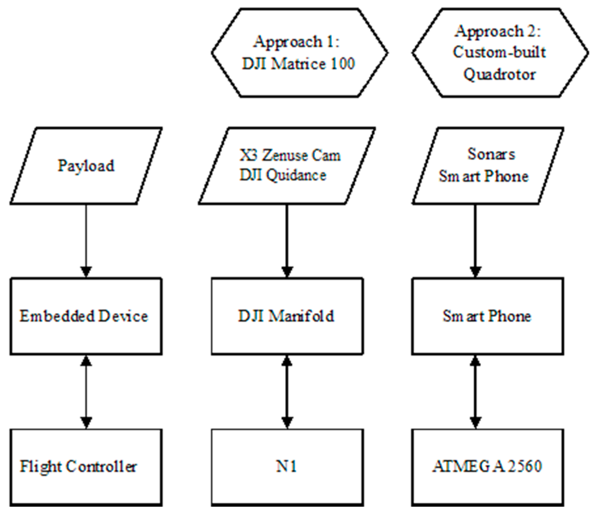
In the subsequently described approaches, we use two different hardware and software settings representing a high and low computational potential of the underlying processing power. Both scenarios are based on the same architectural design (
Figure 1). The flight controller (FC) of the UAV is responsible for the flying attitude and stability of the vehicle. An embedded device interacts with the FC and the peripheral devices (i.e., camera, sonars). The embedded device collects the data from the peripherals, and after processing, it decides about the movement of the UAV (i.e., obstacle avoidance, landing pad detection). The decisions are forwarded to the FC as flight commands (i.e., moving to x, y, z or starting to descend at x m/s).
In the first scenario, the following hardware and software components were used: a DJI Matrice 100 UAV platform (Shenzhen, China), X3 Zenmuse camera (Shenzhen, China) with a gimbal and 4 k @ 30 fps and 1080 p @ 60 fps, a NVIDIA Tegra K1 SOC embedded processor (Santa Clara, CA, USA) (DJI Manifold component), and the DJI Guidance Sensor (Shenzhen, China). In the second scenario, a Quadrotor UAV (Senselab, Chania, Greece), an ATMEGA 2560 flight controller (San Jose, CA, USA) and the processing power of a mobile device are used. The latter constitutes our “smart-drone” implementation [
37], which integrates a standard smart-phone into a custom made UAV carrier. The DJI Matrice 100 comes with the A2 GPS PRO Plus GPS receiver (Shenzhen, China), whereas the custom built “smart-drone” setting is powered by the smart-phone’s GPS receiver. Apparently, custom settings may incorporate more advanced multi-frequency, multi-constellation GNSS boards if sub-centimeter accuracy in AprilTag geolocation is required, yet this implementation is far beyond the scope of the current study.
Various types and sizes of AprilTags are used to denote the survivors and landing targets. The AprilTag markers [
38] are high-contrast, two-dimensional tags designed to be robust to low image resolution, occlusions, rotations, and lighting variation [
38] that have been used in several UAV-related applications [
9,
39,
40] (
Figure 2). Other 2D markers such as ARTag [
41] have been used for UAV localization [
42]; however, in this work, we used AprilTag mainly due to the restrictions set by the aforementioned challenge. However, our approach can be easily adapted to work with other tags.
In both scenarios, the 25h9 AprilTags with dimensions of 6 cm × 6 cm are used to identify the victim, whereas the 16h9 and 36h11 tags with dimensions 40 cm × 40 cm are used to determine the landing platform. In the first scenario, the camera operates in 4 k @ 30 fps and 1080 p @ 60 fps, although in our application, the feed that was retrieved was 720 p @ 60 fps. In the second scenario, the majority of the smart-phone cameras record 1080 p @ 30 fps videos, although several devices support 1080 p @ 60 fps.
The software was developed within the Robotic Operating System (ROS) environment using OpenCV functions. In the first scenario, the DJI libraries for the connection with the drone and camera were utilized, while in the second scenario, the application was implemented on the Android OS.
As described above, the current implementation refers mainly to multi-copters, the majority of which navigate under a tilted fashion, making landing while moving, a non-trivial task. Furthermore, the landing area is considered comparable to the UAV size (i.e., car roof-top), making experimentation and testing quite challenging.
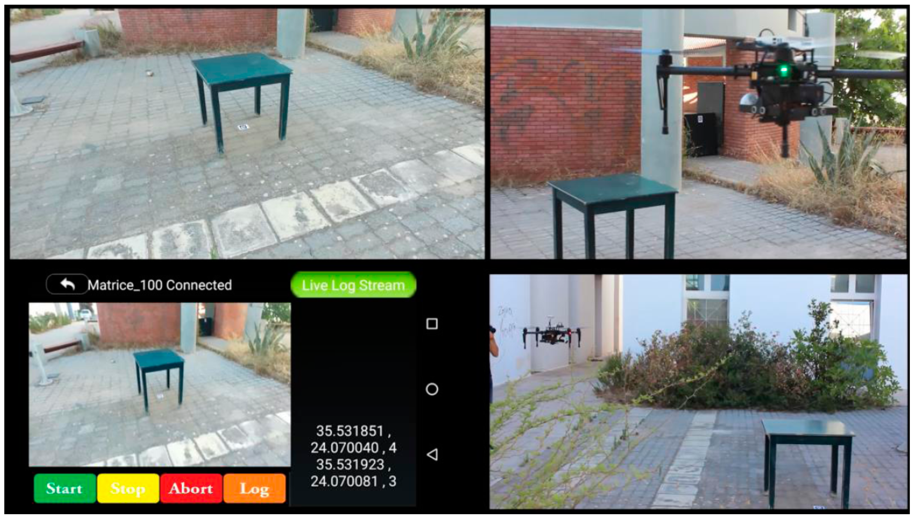
In order for a user to be able to use the described capabilities, an Android application is implemented (
Figure 3, down-left). Through this application, the end user can mark a survey area on a map. The UAV takes off from the moving platform, scans the full area, identifies the required targets; while upon completion, it seeks the landing platform. Using the camera feed, it tries to detect the landing target while approaching the GPS coordinates of the platform. Once the platform has been detected, the drone follows and starts descending towards the platform’s landing pad.
3. Search, Detection and Geo-Location Implementation and Results
3.1. Target Recognition of Survivor AprilTags
As described by the implementation scenario, the UAV, after taking off from the moving platform, navigates towards the search area, where markers in the form of AprilTags are scattered to represent victims (true IDs) and non-victims (false IDs). According to the AprilTag size and placement, flying height, gimbal speed and camera mode (resolution vs. frame rate), the UAV adjusts its speed to accomplish a safe frame acquisition. Each acquired frame by the camera is forwarded to the embedded processor, where the dedicated ROS node processes it in order to detect the AprilTag.
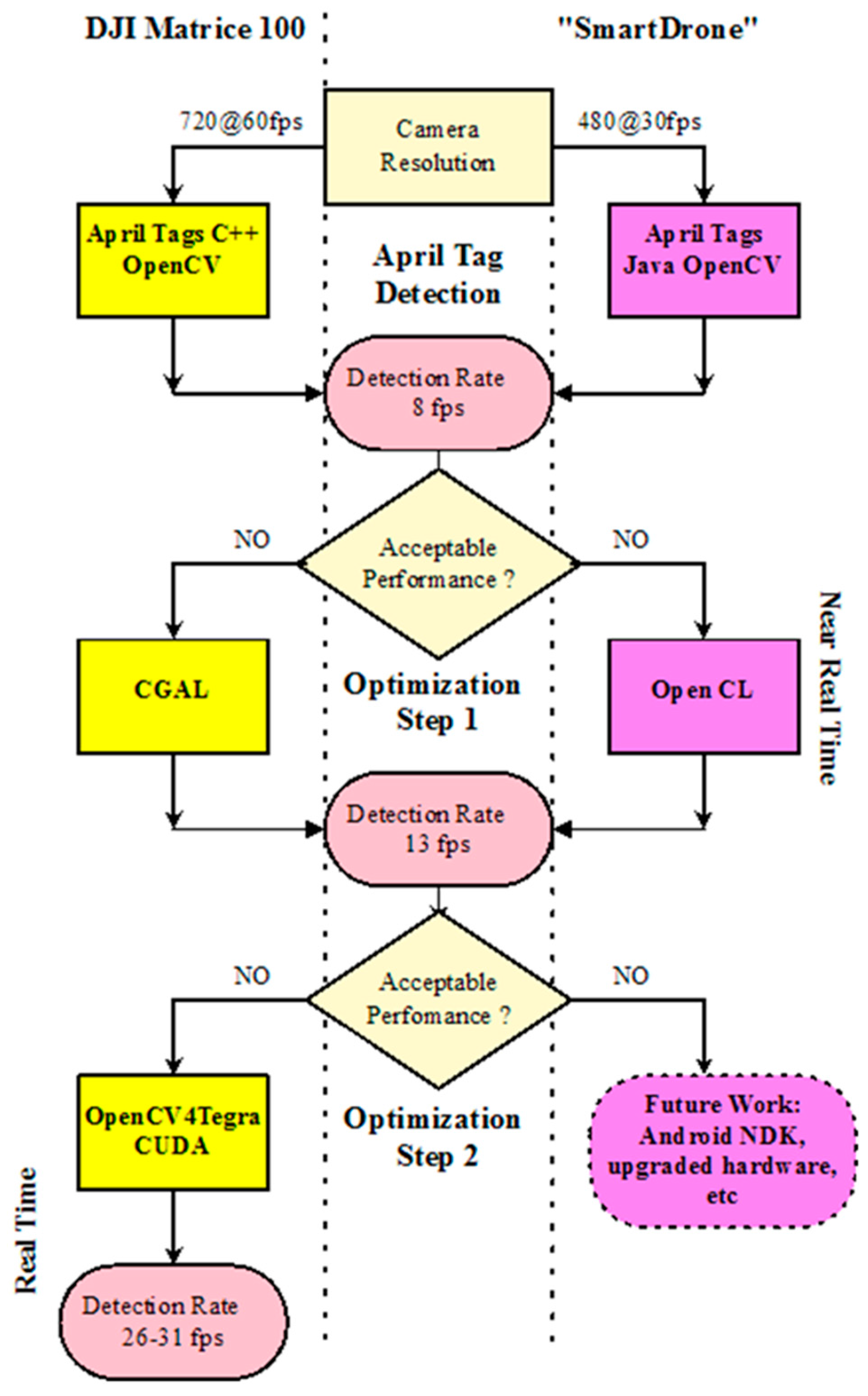
We focused our efforts on implementing a high frame rate detection approach (i.e., ~30 fps), enabling the survivor detection in real-time. Thus, several computational approaches were undertaken (
Figure 4):
Initially, the AprilTags C++ library [
43] that is available in open source under GNU LPGL v2.1 [
44] was employed. This detection approach was successful in identifying and locating the AprilTags but within a low frame rate, mainly due to its poor computational performance.
The second detection approach included the OpenCV implementation based on the solution provided in [
44]. Under this implementation, AprilTag detection and recognition was accomplished under a rate of about eight frames per second.
Although the frame rate was greatly improved, in order to further improve the performance of the algorithm, we used the CGal-based approach available in [
45] to detect quads. This approach gave a great performance upgrade, resulting in 13 frames per second, and the results seemed to be near real-time.
To further enhance the system’s performance, we parallelized the process as Graphics Processing Unit (GPU) functions. This seems to be viable, as the detection process described in [
38] does not involve sophisticated algorithms that demand large local memory [
46]. A similar approach was proposed for QR tags in [
47]. Therefore, we used the OpenCV4Tegra [
48] framework that permits performance of all OpenCV functions in parallel as GPU functions. However, some of the functions described in [
38] are computationally expensive, and, furthermore, they are not available in OpenCV. For example, the “Find Union” function iteratively constructed disjoint subsets inside the initial pixel set of the image, resulting in a processing bottleneck. To overcome such computationally demanding tasks, the CUDA parallel computing platform [
49] was employed along with appropriate modifications to the implementation.
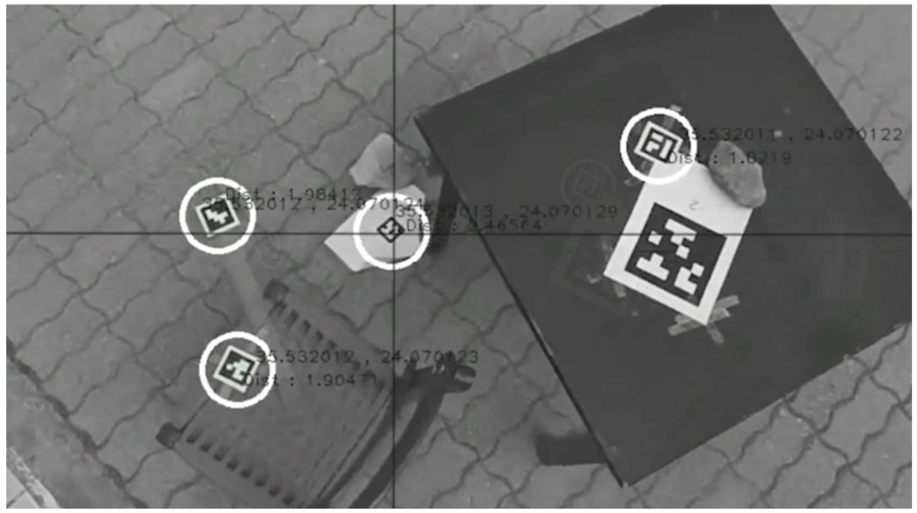
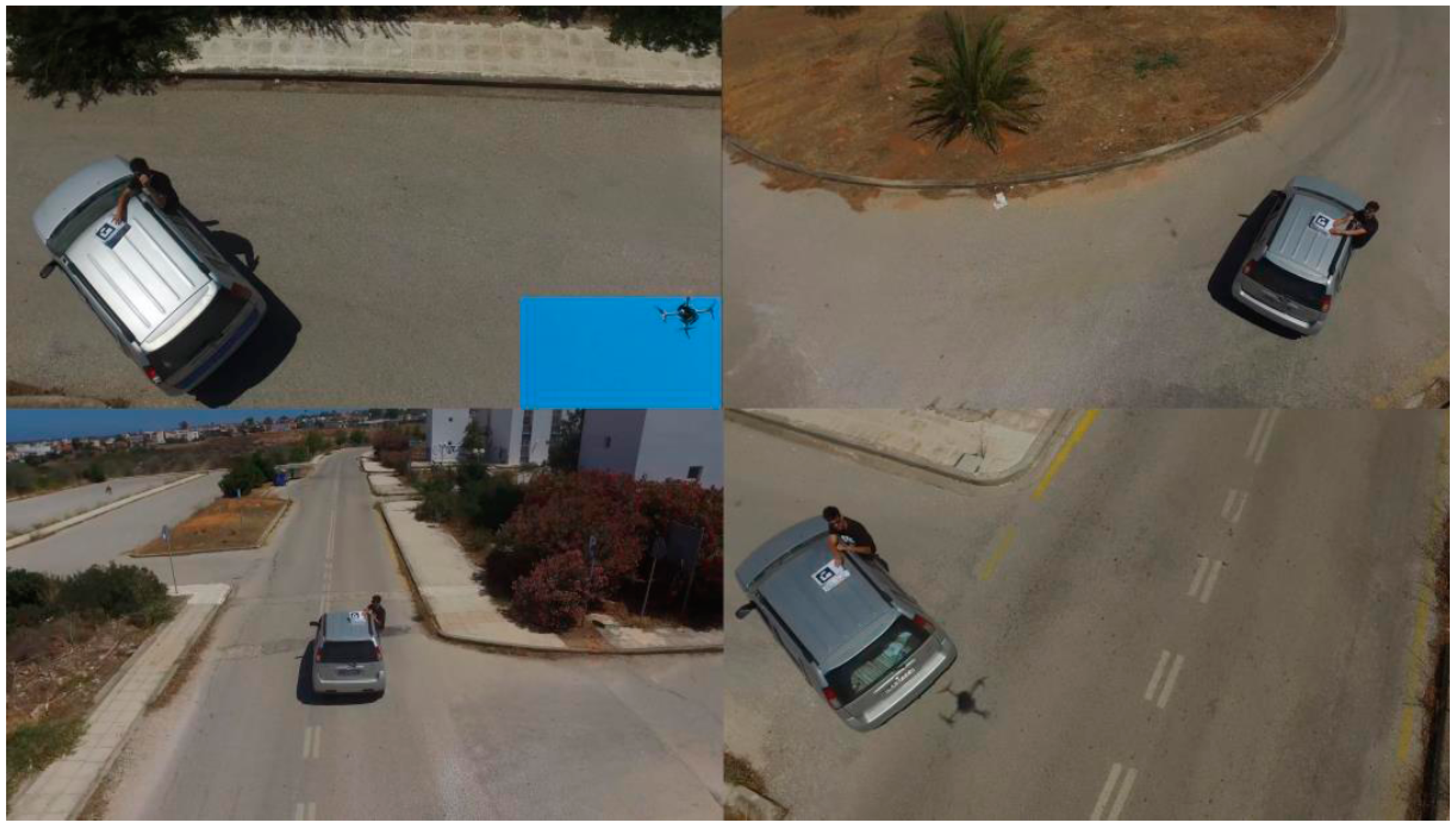
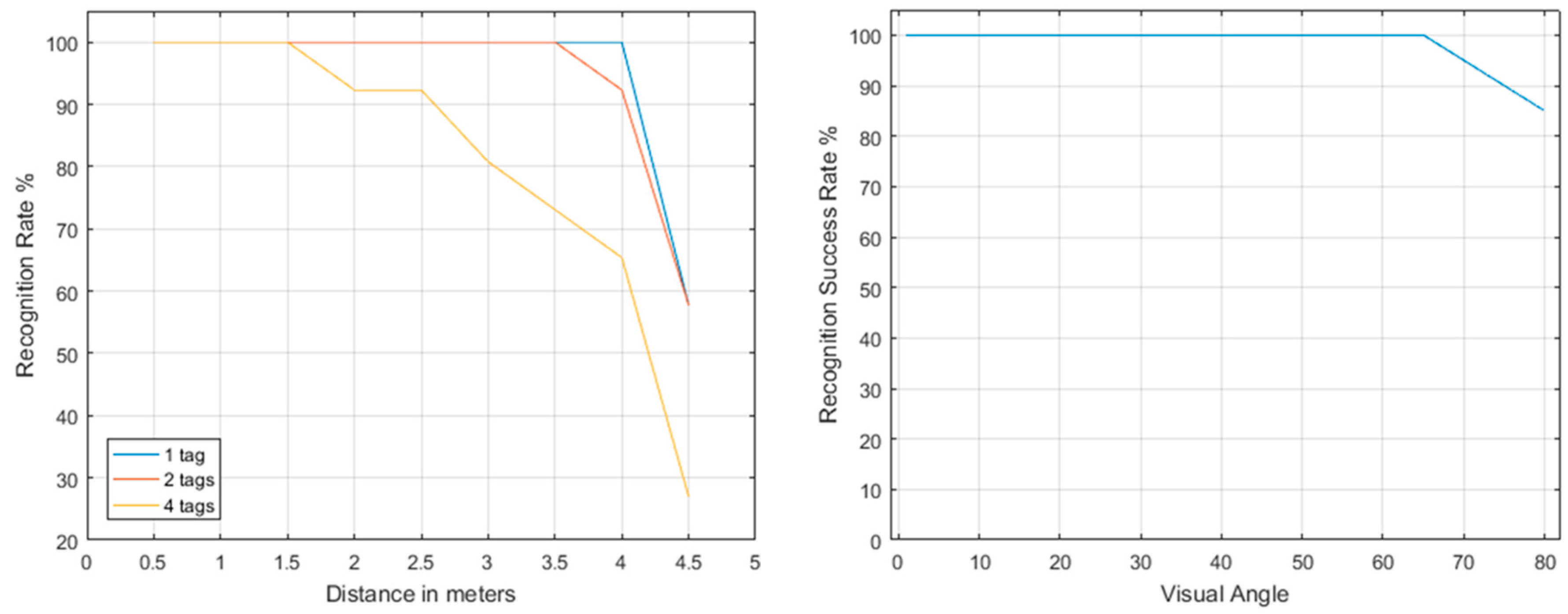
The final AprilTag detection optimization was performed at a rate of 26–31 frames per second. In addition, 6 cm × 6 cm moving AprilTags were detected and identified at a distance of about 4 m, even at extreme visual angles (
Figure 5). Single false positive detections occur rarely, while more than one “true positive” frame recognitions verify the AprilTag ID, making the overall false positive occasions obsolete. When the wind, UAV or survivor movements are considerable, some disruptions in the detection occur, yet they do not contaminate the real-time processing of the implementation. In any case, approaches such as the one presented in [
50] for the control of the UAV velocity and attitude under various disturbances may be further incorporated into the overall system architecture.
3.2. Geo-Location of Survivor AprilTags
The coordinates of the identified AprilTags are determined via the image geometry, gimbal orientation and the UAV GPS readings. However, as an object moves away from the principal point of the frame, large distortions occur in the image geometry. Thus, after the initial identification of the AprilTag, the gimbal moves to position it in the center of the camera’s field-of-view (FOV), the principal point. The detection algorithm uses homography pose estimation to extract the translation and rotation of the AprilTag’s center coordinates with respect to the image center, AprilTag size, and the camera’s intrinsic and extrinsic characteristics. The latter are derived through dedicated camera calibration, performed either offline or even online using: (a) the DJI API (Application Programming Intreface) calls for acquiring camera data; and (b) well known implementations using OpenCV. The AprilTag coordinates are generally calculated relative to the camera center.
In order to provide geographical coordinates to the AprilTag, we have to take into account that three different coordinate systems exist: (1) the 3D UAV system; (2) the gimbal mounted under the frame that houses the camera; and (3) the 2D image coordinates. Thus, the problem is obtaining the world coordinates of the AprilTag marker given its image coordinates. Thus, the following approach was implemented to transform the camera’s to the UAV’s reference system: when a new frame is available for processing, the gimbal and compass values are recorded and their angular distance is calculated. Therefore, the target’s distance and orientation with respect to the UAV can be computed, knowing the geometry of the UAV and its components. As a final step, the UAV’s GPS records are used as inputs into the Vincenty’s Direct Formulae [
51] along with the target’s distance and orientation provided in the previous step. These formulae deliver the target’s GPS coordinates.
Furthermore, in the case of multiple AprilTag detection, the identification and localization initiates by sequentially detecting the closest to the principal point AprilTag, centering it through the camera-gimbal movement and providing its coordinates in real-time (
Figure 2). Then, the specific AprilTag ID is excluded from further searching, and the next one is consecutively centered providing its coordinates. Thus, step by step, all AprilTags are identified only once.
3.3. Area Scanning Approach
The navigation approach in terms of the routing and scanning schedule is a key task that needs to be optimized. A first approach divides the search area in parallel adjacent flying strips, a well-known geometry-based photogrammetric task. Based on the camera’s focal length, flying height, camera’s pixel resolution (x and y), side-lap, angular FOV, target scaling factor, etc., the scan lines can be easily estimated.
The UAV initially retains a constant flight height, determined by the size of the AprilTags with the use of the barometer and sonars onboard. Occlusion and obstacles are undertaken through an obstacle avoidance system (e.g., MB1230 sonar sensor, MaxBotix, Brainerd, MN, USA,) or by determining a height map—elevation model of the area through a sensor system (e.g., DJI Guidance). According to the obstacle avoidance readings, the UAV adjusts its altitude not only to avoid the obstacles but also to lower its elevation and acquire a better view of occluded areas. Under the lowered or elevated positions, a full camera rotation is performed in order to include as many occluded AprilTags as possible for an optimized visibility scan (
Figure 3). The rotation is facilitated by using both gimbal and drone attitude.
4. Takeoff and Landing Approach
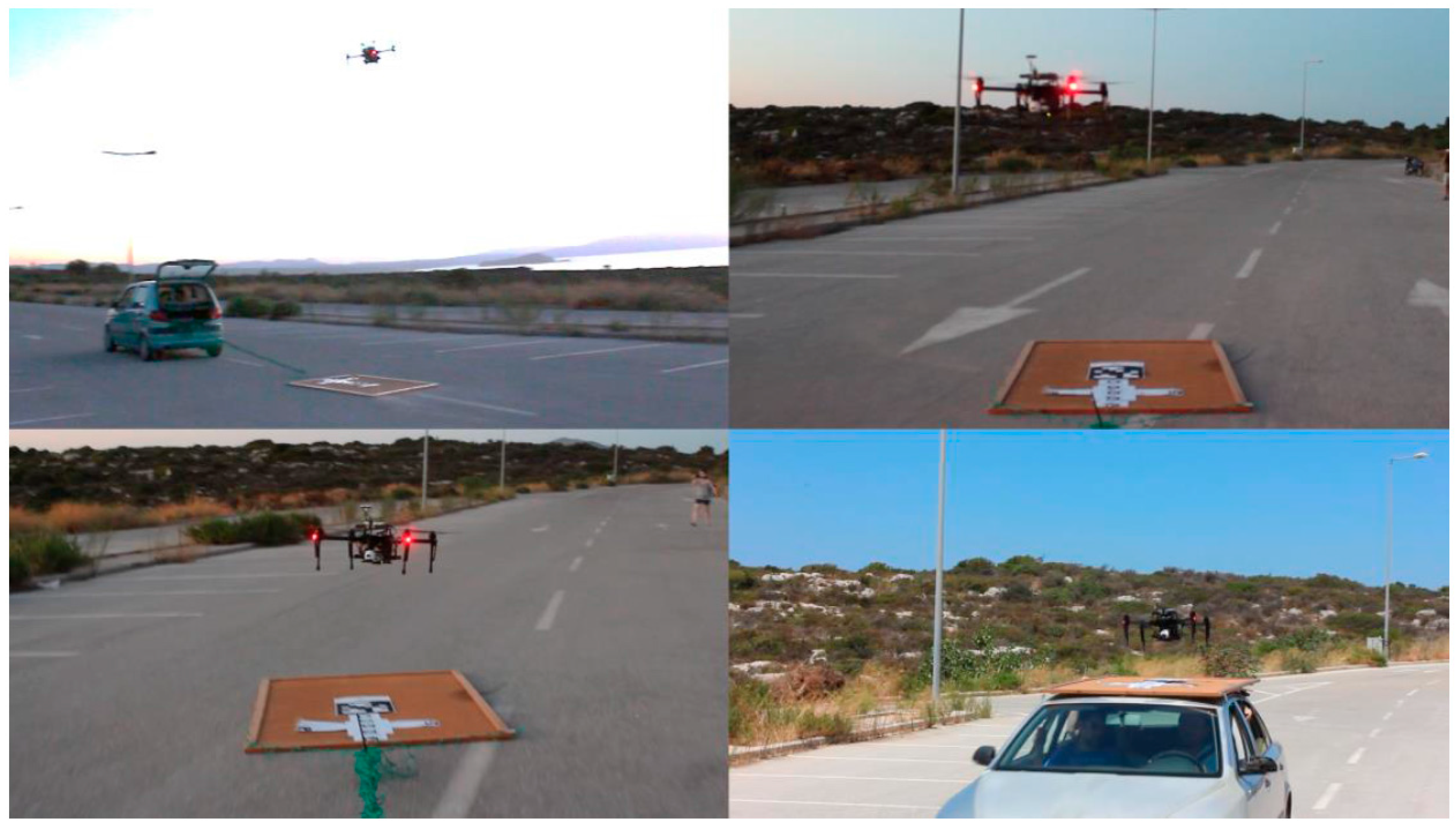
Independent of the UAV setting used (i.e., DJI Matrice 100 or “smart-drone”) takeoff is a straightforward task and no problems were identified since the flight controller, in both settings, is able to manage the stabilization issues that occur when taking off from a moving platform, tested up to 30 km/h (
Figure 6). However, distinct procedures for landing have been taken into consideration.
4.1. High-Computational Processing Setting
In this case, when the landing target is stationary, the actual landing point is within a few centimeters (1–5 cm) from the expected one. When the landing is performed on a moving platform, three distinct approaches were implemented, one based on follow, one on aggressive, and a third on an integrated hybrid mode.
According to the
follow mode, the UAV follows the moving platform from a safe distance and flying height according to the GPS readings of the platform, until the camera locks the AprilTag landing pattern (
Figure 7). The approach of the UAV is gradual, meaning that it lowers its altitude, while the AprilTag remains targeted until it reaches the landing pad. If, for any reason, the AprilTag is lost for a predefined frame number, the UAV rises to retarget the AprilTag.
Under the aggressive approach, the UAV hovers over the area of interest and approximates the platform’s relative angular position moving trajectory through the GPS and then uses the camera to target and lock in the moving platform. This approach uses real-time error correction and trajectory planning, achieved with the use of the OpenCV, ROS API, and DJI API calls. In this approach, the drone detects the vehicle, directly targets the theoretical predicted intersection between their courses, and follows the closest distance approach. The UAV then navigates in a direct approach towards the platform.
The hybrid approach takes advantage of the speed and optimization of the aggressive approach, until the platform is close enough to identify the landing AprilTag. Then, the landing procedure of the follow approach is performed. Thus, the UAV selects the shortest path to the target, and at the final stage of approach, tries to hover above the target and slowly descend into landing.
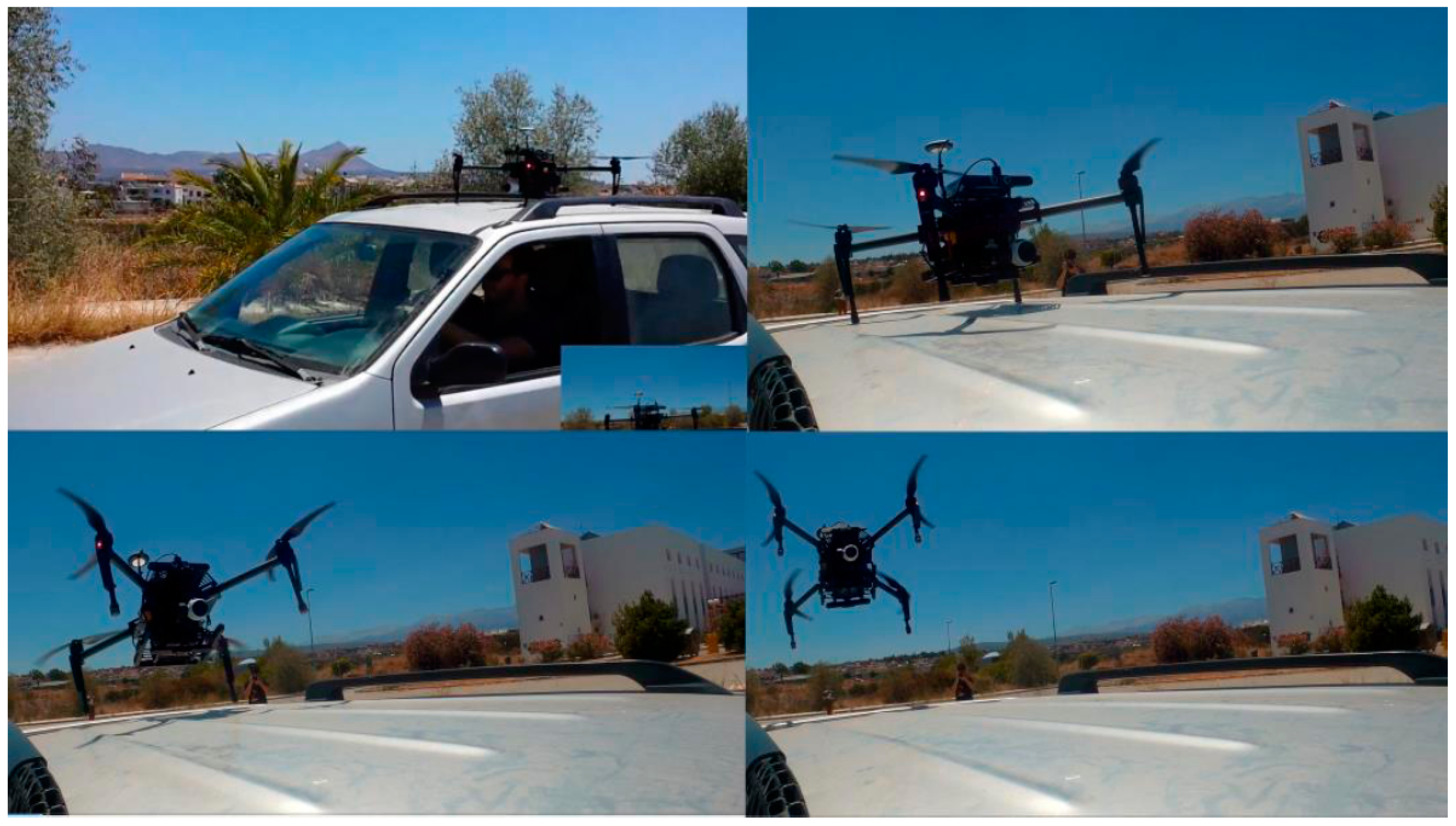
All approaches were tested under various platform speeds and conditions. We had successful touchdowns from stationary targets to moving targets, with speeds reaching 30 km/h. The moving target scenarios tested included both following a target and landing, and also locating a distant target, reaching it and then landing (
Figure 8). In our testing, all landings were successful in approaching the platform; however, at high speeds and wide platform turning angles, the final 25 cm of descent resulted sometimes in less accurate landings and instability.
Therefore, depending on the moving platform type, when its speed reaches more than 20 km/h, a stabilizing practice should be devised in order to alleviate the gradual friction of the UAV landing legs that may lead to unstable landing or even crashing. Such implementations may include reconfigurable perching elements [
52], electromagnets in landing legs or platform, fastening straps, retractable hooks, etc.
4.2. Low-Computational Processing Setting
The previous section detailed the procedures for landing a UAV powered with a high-computational processing unit on a moving platform. In this section, we discuss the case of the smart-drone unit, where the obstacle avoidance and landing procedures need to be revisited.
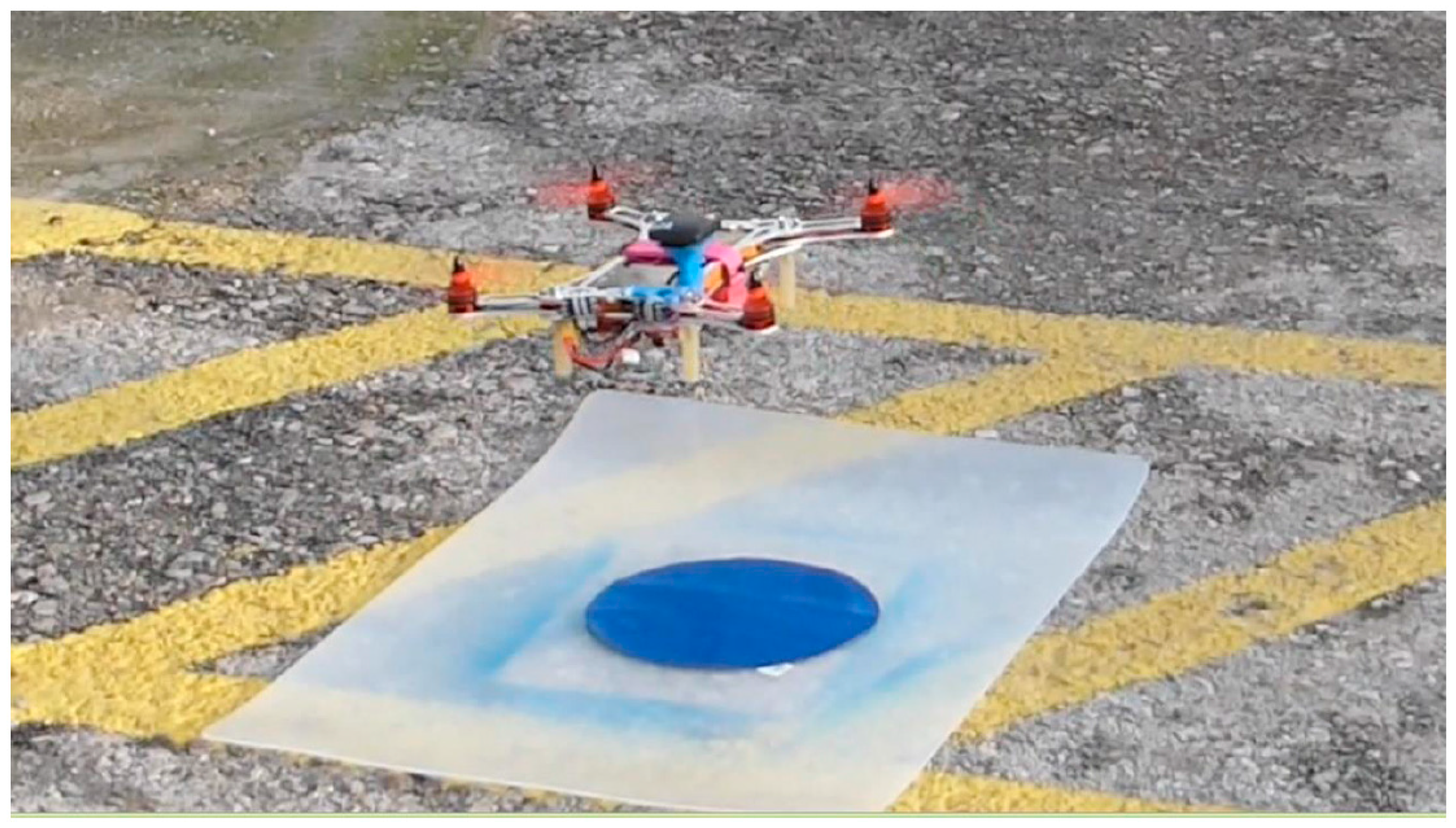
In order to detect the landing base, real-time image processing takes place in the smart-drone’s mobile device (
Figure 9). More specifically, the acquired feed from the smart-phone camera is processed in real-time to detect the landing base. The base is designed as a discrete circle on a homogenous background that is colored in such a way that it can be easily distinguished from the surroundings. From an algorithmic point of view, each acquired still frame from the image stream is transformed to HSV (Hue, Saturation, Value), and the contours that are relative to the target’s specific HSV values are calculated. After this filtering, the circle areas in the image are determined through the Hough circles function, so that that the base can be identified. In order to estimate the UAV distance from the landing base, the pose of the target circle needs to be determined. When facing the target at a 90° angle, the distance is estimated by calculating the target size in pixels and referencing it to its calibrated values. When facing from a different angle, we calculate the homography and extract the rotation and translation of the target. Thus, while the exact position of the object into the 3D space and its projection to a 2D surface are determined, we estimate the distance by considering the pixel area of the target.
The processing is undertaken by the smart-phone processor, and flight correction data are forwarded to the flight controller in order to change its position to new relative (x, y, z) coordinates and descend at a given rate, until the UAV reaches the landing pad.
5. Discussion and Conclusions
In this study, we presented a UAV related scenario representing an abundance of applications characterized by search, detect, geo-locate and automatic landing components. The key function of our approach is the UAV computational autonomy, which adjusts its attitude according to the specific environment. The underlying application adheres to a Search and Rescue paradigm, where the UAV takes off, scans a predefined area, geo-locates possible survivor targets, and, upon completion, returns to land on a moving platform. In order to support computational autonomy and perform “expensive” real-time tasks, we integrated high and relatively low-computational embedded systems.
Both implementations were able to identify the targets and proceeded successfully to the landing platforms. The first approach, however, proved more reliable, as it was able to keep on tracking and approaching in real-time, fast moving landing targets. The low-computational smart-drone approach seems very promising, but still needs improvement in the stabilization system of the phone’s camera. Specifically, a gimbal-like mechanism needs to be constructed specifically for the mobile phone.
The challenging tasks of the described scenario include the real-time target detection and identification, and the follow, approach and landing implementations in the moving platform. Real time target detection was accomplished using a GPU parallelization, in order to achieve 30 fps processing speed. The significance of the processing frame rate is justified due to the high speed landing platforms, under which our implementation succeeded with following and landing upon. In several other studies, either the platform velocity was low, or the size of the moving platform was considerably large in order to enable a safe landing [
32,
33,
34,
35]. To the best of our knowledge, there are only a few studies that propose techniques for automated UAV landing on fast moving (i.e., >20 km/h) cars [
35]. Even then, the platform speed facilitates landing of airplane-like UAVs, since it actually provides a moving air runway.
For multi-copters and relatively small landing areas, our implementation provides a novel approach scheme. Thus, our “aggressive” approach for the multi-copters is used to provide a robust and direct way for the UAV to reach the landing target. Furthermore, the usual “follow” mode used in recreation or most of the commercial follow-me approaches remains dangerous when occluded, and vegetated areas are evident since the UAV will adjust its attitude relative to the moving target under a lagged approach. The “aggressive” approach, when utilized after the landing target camera locking, ensures an obstacle-free corridor towards a safe landing.
Another subtle detail of our approach is the real-time geo-location capability that provides geographic coordinates under an optimized implementation. Since camera distortion may provide inaccurate location estimations, principal point targeting, pose extraction and calibration are used to provide more accurate coordinates. Geo-location is crucial especially in SAR applications in large regions, such as the ocean, where multiple people may be in danger. The exact location of multiple people is not achieved by today’s means, since the common practice involves merely visual inspection, especially when UAVs fly relatively high. Under our approach, the authorities along with the rescue and recovery teams, may receive, in real-time, correct coordinates for multiple moving people, all at once, assisting with precise and timely rescue.
It is also noted that the whole methodology is not limited in SAR applications, but seamlessly reflects other detection scenarios including environmental monitoring and pattern recognition (overgrazing, deforestation, etc.), vegetation identification for endangered species geo-location, animal observation, protection from poaching, etc.
When the moving platform speed is more than 20 km/h, a stabilizing system should be used to protect the UAV from flipping or crashing. Thus, for secure landing, electromagnets in landing legs or platform, suction systems or servo-actuated hooks are some solutions that currently are being tested by our group.
Acknowledgments
We would like to acknowledge DJI who under the DJI–Ford 2016 challenge offered free of charge the equipment of the Matrice 100, Manifold, X3 Zenmuse camera, Guidance, replacement parts and the challenge tasks.
Author Contributions
Sarantis Kyritsis, Angelos Antonopoulos, Theofilos Chanialakis and Emmanouel Stefanakis were the main developers of the implementations, and, along with Achilles Tripolitsiotis, performed the tests. Christos Linardos, as a certified airplane pilot, designed the landing approach scenario, and Achilles Tripolitsiotis, along with Sarantis Kyritsis and Panagiotis Partsinevelos, who served as the coordinator of the research group, wrote the paper.
Conflicts of Interest
The authors declare no conflict of interest. The founding sponsors had no role in the design of the study; in the collection, analyses, or interpretation of data; in the writing of the manuscript, and in the decision to publish the results.
References
- GrandViewResearch. Available online: http://www.grandviewresearch.com/industry-analysis/commercial-uav-market (accessed on 15 August 2016).
- Austin, R. Unmanned Aircraft Systems: UAVs design, development and deployment. In Aerospace Series; Moir, I., Seabridge, A., Langton, R., Eds.; Wiley and Sons: Chichester, UK, 2010. [Google Scholar]
- Ham, Y.; Ham, K.K.; Lin, J.J.; Golparvar-Fard, M. Visual monitoring of civil infrastructure systems via camera-equipped unmanned aerial vehicles (UAVs): A review of related works. Vis. Eng. 2016, 4, 1. [Google Scholar] [CrossRef]
- Chan, B.; Guan, H.; Blumenstein, M. Towards UAV-based bridge inspection systems: A review and an application perspective. Struct. Monit. Maint. 2015, 2, 283–300. [Google Scholar] [CrossRef]
- Eschmann, C.; Kuo, C.M.; Kuo, C.H.; Boller, C. High-resolution multisensor infrastructure inspection with unmanned aircraft systems. ISPRS 2013, XL-1/W2, 125–129. [Google Scholar] [CrossRef]
- Máthé, K.; Busoniu, L. Vision and control for UAVs: A survey of general methods and of inexpensive platforms for infrastructure inspection. Sensors 2015, 15, 14887–14916. [Google Scholar] [CrossRef] [PubMed]
- Bryson, M.; Sukkarieh, S. Inertial sensor-based simultaneous localization and mapping for UAVs. In Handbook of Unmanned Aerial Vehicle; Valavanis, K., Vachtsevanos, G., Eds.; Springer: Dordrecht, The Netherlands, 2015; pp. 401–431. [Google Scholar]
- Dijkshoorn, N. Simultaneous Localization and Mapping with the AR. Drone. Master’s Thesis, Universiteit van Amsterdam: Amsterdam, The Netherlands, 14 July 2012. [Google Scholar]
- Li, C. Simultaneous Localization and Mapping Implementations via Probabilistic Programming with Unmanned Aerial Vehicles; Research Project Report, Massachusetts Institute of Technology: Boston, MA, USA, 28 July 2015. [Google Scholar]
- Dehghan, S.M.M.; Moradi, H. SLAM-inspired simultaneous localization of UAV and RF sources with unknown transmitted power. Trans. Inst. Meas. Control 2016, 38, 895–907. [Google Scholar] [CrossRef]
- Gruz, G.; Encarnação, P. Obstacle avoidance for unmanned aerial vehicles. J. Intell. Robot. Syst. 2012, 65, 203–217. [Google Scholar] [CrossRef]
- Gageik, N.; Benz, P.; Montenegro, S. Obstacle detection and collision avoidance for a UAV with complementary low-cost sensors. IEEE Access 2015, 3, 599–609. [Google Scholar] [CrossRef]
- Call, B. Obstacle Avoidance for Unmanned Air Vehicles. Master’s Thesis, Brigham Young University, Provo, UT, USA, 11 December 2006. [Google Scholar]
- Barry, A. High-Speed Autonomous Obstacle Avoidance with Pushbroom Stereo. Ph.D. Thesis, Massachusetts Institute of Technology, Cambridge, MA, USA, February 2016. [Google Scholar]
- Partsinevelos, P.; Agadakos, I.; Athanasiou, V.; Papaefstathiou, I.; Mertikas, S.; Kyritsis, S.; Tripolitsiotis, A.; Zervos, P. On-board computational efficiency in real-time UAV embedded terrain reconstruction. Geophys. Res. Abstr. 2014, 16, 9837. [Google Scholar]
- Bulatov, D.; Solbrig, P.; Gross, H.; Wernerus, P.; Repasi, E.; Heipke, C. Context-based urban terrain reconstruction from UAV-videos for geoinformation applications. In Proceedings of the Conference on Unmanned Aerial Vehicle in Geomatics, Zurich, Switzerland, 14–16 September 2011.
- Gottlieb, Y.; Shima, T. UAVs task and motion planning in the presence of obstacles and prioritized targets. Sensors 2015, 15, 29734–29764. [Google Scholar] [CrossRef] [PubMed]
- Witayangkurn, A.; Nagai, M.; Honda, K.; Dailey, M.; Shibasaki, R. Real-time monitoring system using unmanned aerial vehicle integrated with sensor observation service. In Proceedings of the Conference on Unmanned Aerial Vehicle in Geomatics, Zurich, Switzerland, 14–16 September 2011.
- Nagai, M.; Witayangkurn, A.; Honda, K.; Shibasaki, R. UAV-based sensor web monitoring system. Int. J. Navig. Obs. 2012, 2012. [Google Scholar] [CrossRef]
- Bravo, R.; Leiras, A. Literature review of the application of UAVs in humanitarian relief. In Proceedings of the XXXV Encontro Nacional de Engenharia de Producao, Fortaleza, Brazil, 13–16 October 2015.
- Baiocchi, V.; Dominici, D.; Milone, M.V.; Mormile, M. Development of a software to plan UAVs stereoscopic flight: An application on post earthquake scenario in L’Aquila city. In Computational Science and its Applications-ICCSA 2013; Murgante, B., Misra, S., Carlini, M., Torre, C.M., Nguyen, H.Q., Taniar, D., Apduhan, B.O., Gervasi, O., Eds.; Springer: Berlin, Germany, 2013; pp. 150–165. [Google Scholar]
- Yeong, S.P.; King, L.M.; Dol, S.S. A review on marine search and rescue operations using unmanned aerial vehicles. Int. J. Mech. Aerosp. Ind. Mech. Manuf. Eng. 2015, 9, 396–399. [Google Scholar]
- Waharte, S.; Trigoni, N. Supporting search and rescue operation with UAVs. In Proceedings of the 2010 International Conference on Emerging Security Technologies (EST), Canterbury, UK, 6–7 September 2010; pp. 142–147.
- Herissé, B.; Hamel, T.; Mahony, R.; Russotto, F.X. Landing a VTOL unmanned aerial vehicle on a moving platform using optical flow. IEEE Trans. Robot. 2012, 28, 1–13. [Google Scholar] [CrossRef]
- Sapiralli, S. Vision-based autonomous landing of an helicopter on a moving target. In Proceedings of the AIAA Guidance, Navigation, and Control Conference, Chicago, IL, USA, 10–13 August 2011.
- Araar, O.; Aouf, N.; Vitanov, I. Vision based autonomous landing of multirotor UAV on moving platform. J. Intell. Robot. Syst. 2016, 1–16. [Google Scholar] [CrossRef]
- Wenzel, K.E.; Masselli, A.; Zell, A. Automatic take off, tracking and landing of a miniature UAV on a moving carrier vehicle. J. Intell. Robot. Syst. 2011, 61, 221–238. [Google Scholar] [CrossRef]
- Alarcon, F.; Santamaria, D.; Viguria, A. UAV helicopter relative state estimation for autonomous landing on platforms in a GPS-denied scenario. IFAC-PapersOnLine 2015, 48, 37–42. [Google Scholar] [CrossRef]
- Oh, S.; Pathak, K.; Agrawal, S. Autonomous helicopter landing on a moving platform using a tether. In Proceedings of the 2005 IEEE International Conference on Robotics and Automation, Barcelona, Spain, 18–22 April 2005; pp. 3960–3965.
- Wu, C.; Song, D.; Qi, J.; Han, J. Autonomous landing of an unmanned helicopter on a moving platform based on LP path planning. In Proceedings of the 8th International Conference on Intelligent Unmanned Systems (ICIUS 2012), Singapore, 22–24 October 2012; pp. 978–981.
- Kim, J.; Jung, Y.; Lee, D.; Shim, D.H. Outdoor autonomous landing on a moving platform for quadrotors using an omnidirectional camera. In Proceedings of the International Conference on Unmanned Aircraft Systems (ICUAS 2014), Orlando, FL, USA, 27–30 May 2014.
- Xu, G.; Zhang, Y.; Ji, S.; Cheng, Y.; Tian, Y. Research on computer vision-based for UAV autonomous landing on a ship. Pattern Recognit. Lett. 2009, 30, 600–605. [Google Scholar] [CrossRef]
- Sanchez-Lopez, J.L.; Pestana, J.; Saripalli, S.; Campoy, P. An approach toward visual autonomous ship board landing of a VTOL UAV. J. Intell. Robot. Syst. 2014, 74, 113–127. [Google Scholar] [CrossRef]
- Fourie, K.C. The Autonomous Landing of an Unmanned Helicopter on a Moving Platform. Master’s Thesis, Stellenbosch University, Stellenbosch, South Africa, December 2015. [Google Scholar]
- Frølich, M. Automatic Ship Landing System for Fixed-Wing UAV. Master’s Thesis, Norwegian University of Science and Technology, Trondheim, Norway, June 2015. [Google Scholar]
- DLR. Available online: http://www.dlr.de/dlr/en/desktopdefault.aspx/tabid-10081/151_read-16413/#/gallery/21679 (accessed on 20 March 2016).
- Robotic Trends. Available online: http://www.roboticstrends.com/photo/meet_the_6_finalists_of_the_drones_for_good_award/2 (accessed on 25 February 2016).
- Olson, E. AprilTag: A robust and flexible visual fiducial system. In Proceedings of the 2011 IEEE International Conference on Robotics and Automation, Shanghai, China, 9–13 May 2011; pp. 3400–3407.
- Chaves, S.M.; Wolcott, R.W.; Eustice, R.M. NEEC Research: Toward GPS-denied landing of unmanned aerial vehicles on ships at sea. Naval Eng. J. 2015, 127, 23–35. [Google Scholar]
- Ling, K. Precision Landing of a Quadrotor UAV on a Moving Target Using Low-Cost Sensors. Master’s Thesis, University of Waterloo, Waterloo, ON, Canada, 16 September 2014. [Google Scholar]
- Fiala, M. ARTag, a fiducial marker system using digital techniques. In Proceedings of the 2005 IEEE Computer Society Conference on Computer Vision and Pattern Recognition (CVPR ‘05), Washington, DC, USA, 20–25 June 2005; Volume 2, pp. 590–596.
- Jayatilleke, L.; Zhang, N. Landmark-based localization for unmanned aerial vehicles. In Proceedings of the 2013 IEEE International Systems Conference (SysCon 2013), Orlando, FL, USA, 15–18 April 2013.
- Kaess, M. AprilTags C++ Library. Available online: http://people.csail.mit.edu/kaess/apriltags/ (accessed on 10 April 2016).
- GNU Operating System. Available online: https://www.gnu.org/licenses/old-licenses/lgpl-2.1.en.html (accessed on 10 April 2016).
- Swatbotics. Available online: https://github.com/swatbotics/apriltags-cpp (accessed on 10 April 2016).
- Asano, S.; Maruyama, T.; Yamaguchi, Y. Performance comparison of FPGA, GPU and CPU in image processing. In Proceedings of the 2009 Field Programmable Logic and Applications (FPL 2009), Prague, Czech Republic, 31 August–2 September 2009; pp. 126–131.
- Sörös, G. GPU-Accelerated Joint 1D and 2D Barcode Localization on Smartphones. In Proceedings of the 39th International Conference on Acoustics, Speech, and Signal Processing (ICASSP 2014), Florence, Italy, 4–9 May 2014; pp. 5095–5099.
- NVIDIA. Linux for Tegra R24.2. Available online: https://developer.nvidia.com/embedded/linux-tegra (accessed on 10 April 2016).
- NVIDIA. CUDA. Available online: http://www.nvidia.com/object/cuda_home_new.html (accessed on 10 April 2016).
- Xiong, H.; Yuan, R.; Yi, J.; Fan, G.; Jing, F. Disturbance rejection in UAV’s velocity and attitude control: Problems and Solutions. In Proceedings of the 30th Chinese Control Conference, Yantai, China, 22–24 July 2011; pp. 6293–6298.
- Vincenty, T. Direct and inverse solutions of geodesics on the ellipsoid with application of nested equations. Surv. Rev. 1975, 23, 88–93. [Google Scholar] [CrossRef]
- Erbil, M.A.; Prior, S.D.; Keane, A.J. Design optimisation of a reconfigurable perching element for vertical take-off and landing unmanned aerial vehicles. Int. J. Micro Air Veh. 2013, 53, 207–228. [Google Scholar] [CrossRef]
© 2016 by the authors; licensee MDPI, Basel, Switzerland. This article is an open access article distributed under the terms and conditions of the Creative Commons Attribution (CC-BY) license (http://creativecommons.org/licenses/by/4.0/).


