
Fabrication of a Miniaturized ZnO Nanowire Accelerometer and Its Performance Tests


Abstract
:1. Introduction
2. Design
3. Experiments
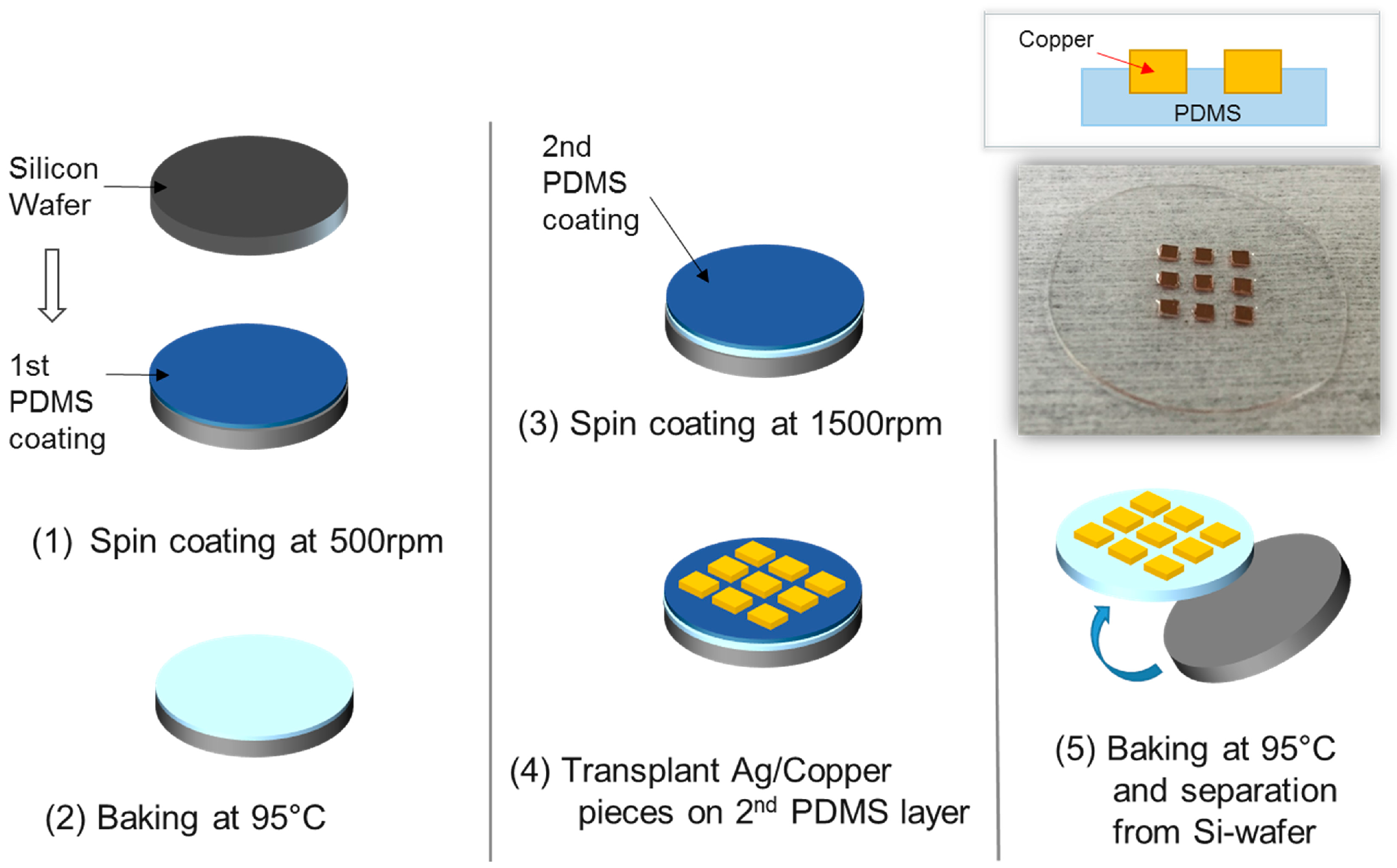
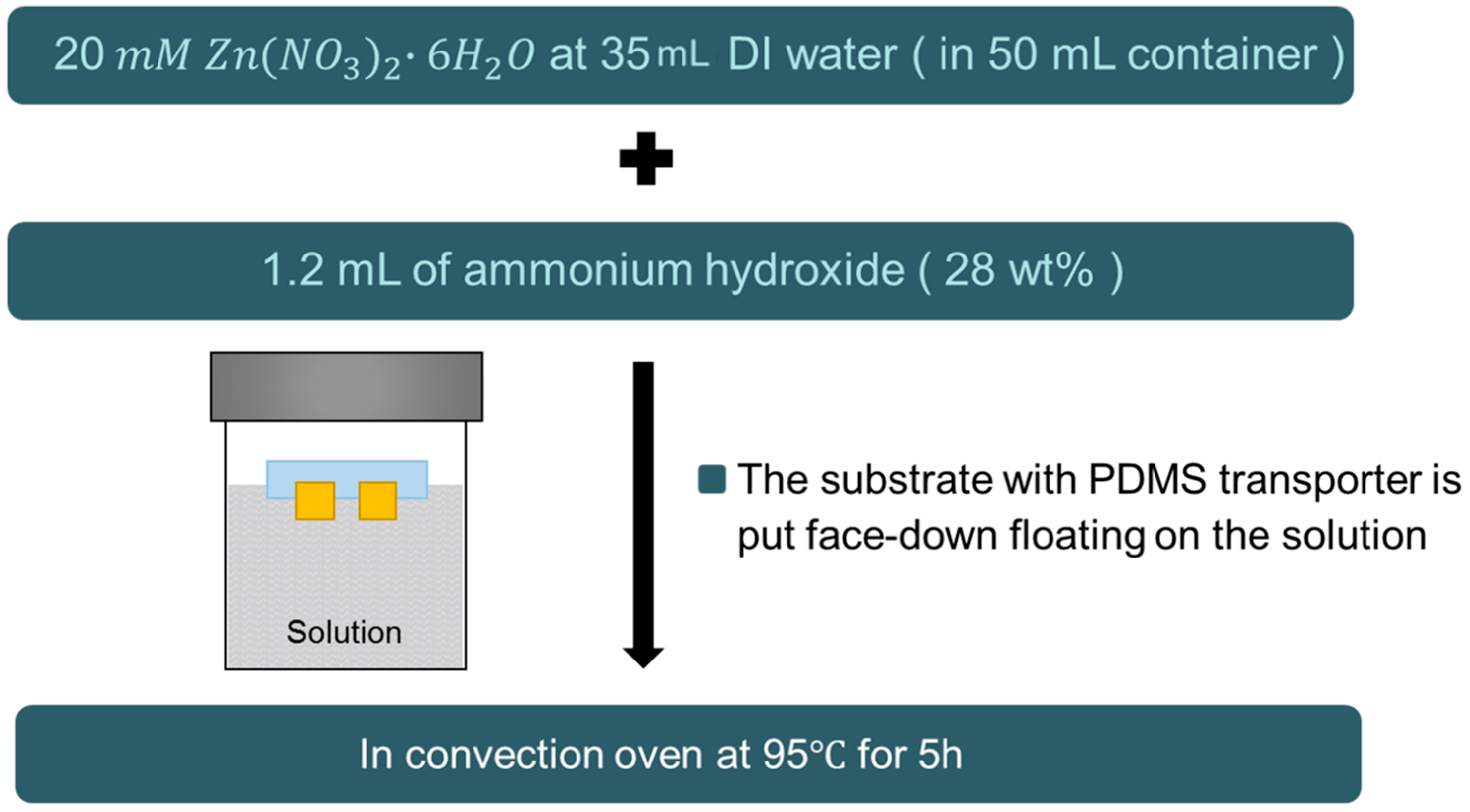
3.1. Fabrication
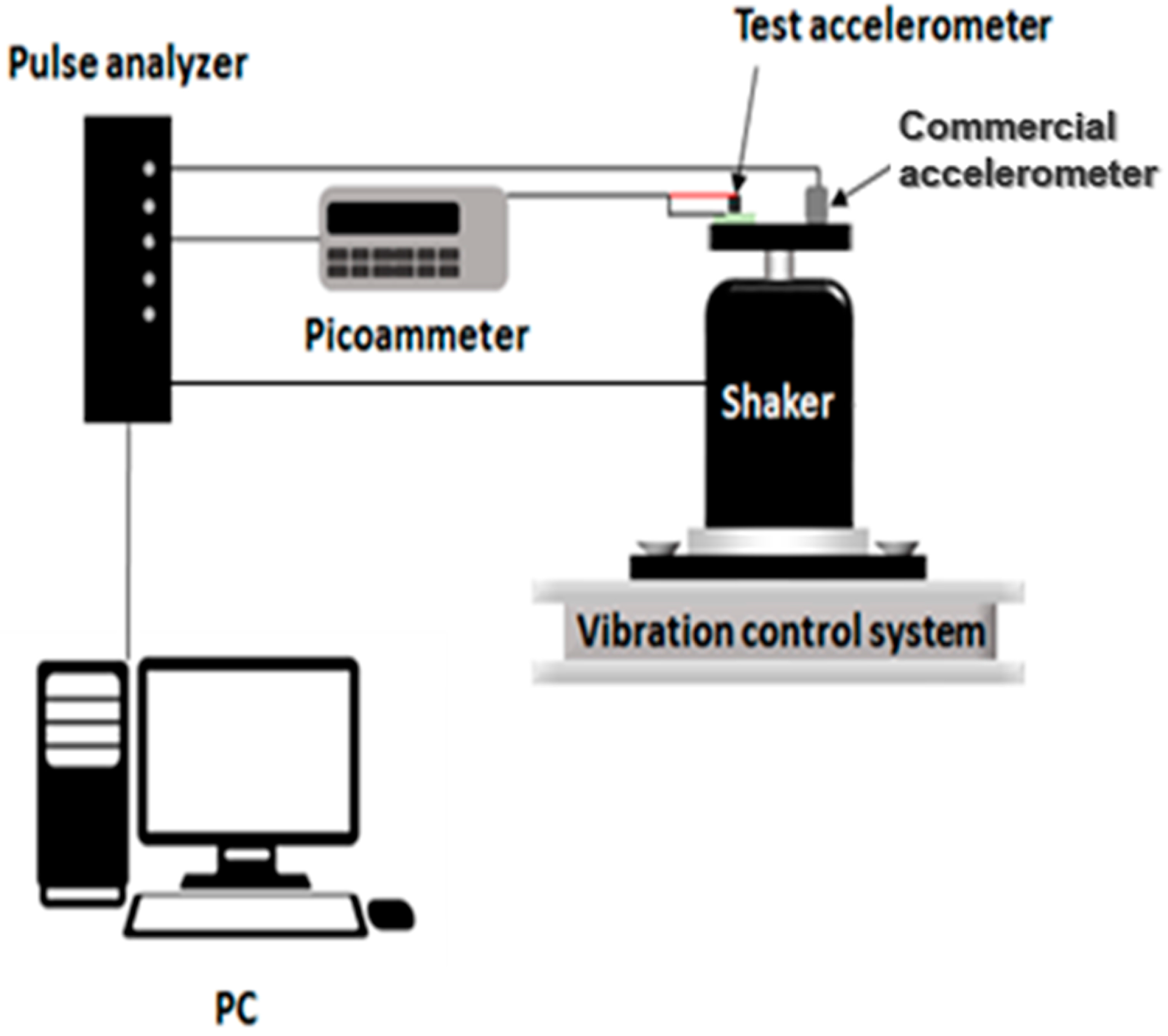
3.2. Performance Test
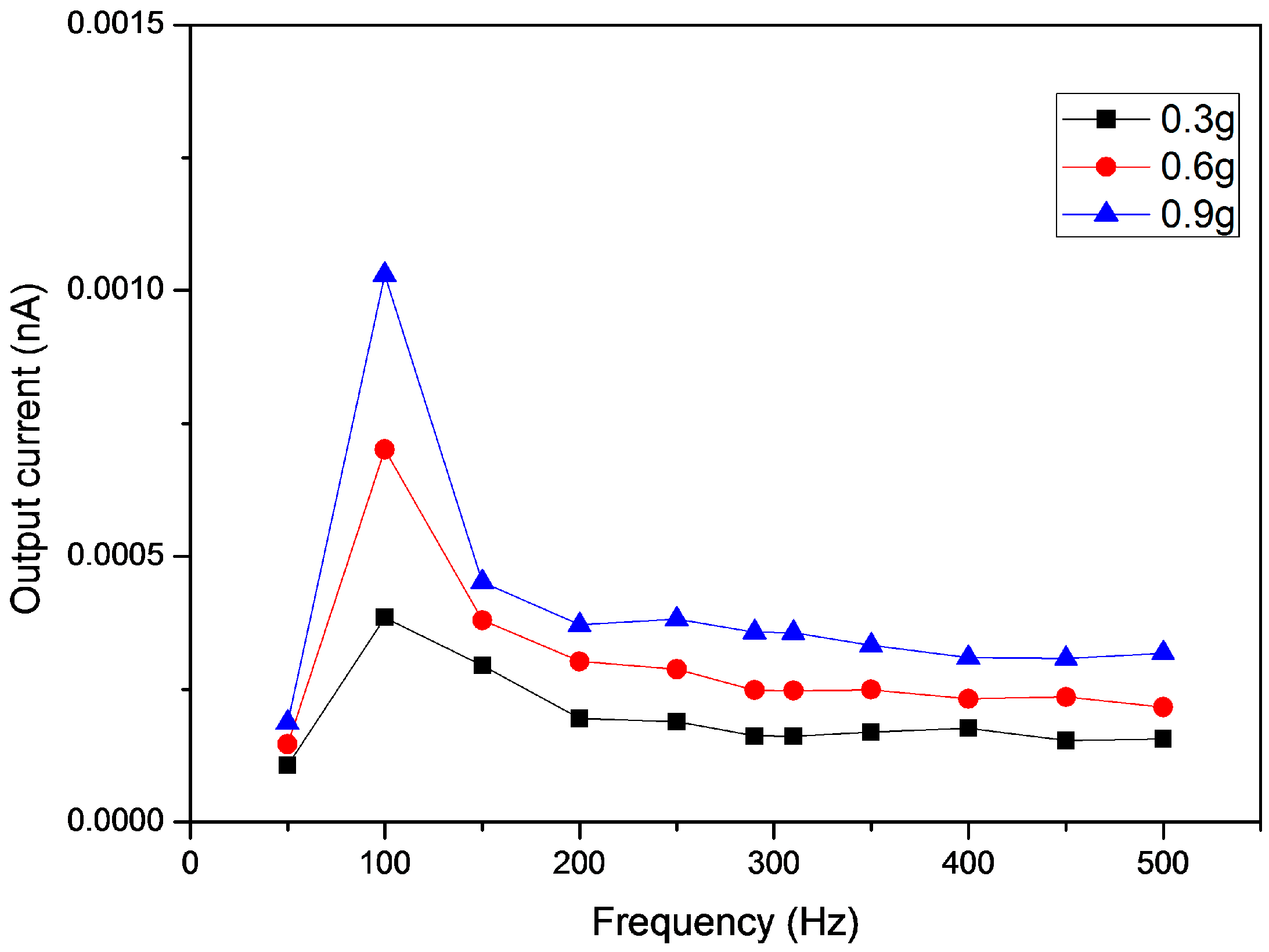
4. Results and Discussion
5. Conclusions
Acknowledgments
Author Contributions
Conflicts of Interest
References
- Ullah, F.; Park, K. Development of a surface-based virtual dental sculpting simulator with multimodal feedback. Int. J. Precis. Eng. Manuf. 2013, 14, 577–587. [Google Scholar] [CrossRef]
- Ko, H.U.; Kim, H.C.; Kim, J.; Kim, S.Y. Miniaturized 3 × 3 array film vibrotactile actuator made with cellulose acetate for virtual reality simulators. Smart Mater. Struct. 2015, 24, 055018. [Google Scholar] [CrossRef]
- Johnson, K.O. The roles and functions of cutaneous mechanoreceptors. Curr. Opin. Neurobiol. 2001, 11, 455–461. [Google Scholar] [CrossRef]
- Kang, D.W.; Choi, J.S.; Lee, J.W.; Tack, G.R. Prediction of energy consumption according to physical activity intensity in daily life using accelerometer. Int. J. Precis. Eng. Manuf. 2012, 13, 617–621. [Google Scholar] [CrossRef]
- Vijaya, M.S. Piezoelectric Materials and Devices: Applications in Engineering and Medical Sciences; CRC Press: Boca Raton, FL, USA, 2012; pp. 60–64. [Google Scholar]
- De Silva, C.W. Sensors and Actuators: Engineering System Instrumentation, 2nd ed.; CRC Press: Boca Raton, FL, USA, 2015; pp. 355–357. [Google Scholar]
- Wang, Z.L.; Song, J. Piezoelectric nanogenerators based on zinc oxide nanowire arrays. Science 2006, 312, 242–246. [Google Scholar] [CrossRef]
- Ko, H.U.; Mun, S.; Min, S.K.; Kim, G.W.; Kim, J. Fabrication of cellulose ZnO hybrid nanocomposite and its strain sensing behavior. Materials 2014, 7, 7000–7009. [Google Scholar] [CrossRef]
- Kumar, B.; Kim, S.W. Energy harvesting based on semiconducting piezoelectric ZnO nanostructures. Nano Energy 2012, 1, 342–355. [Google Scholar] [CrossRef]
- Malakooti, M.H.; Patterson, B.A.; Hwang, H.S.; Sodano, H.A. ZnO nanowire interfaces for high strength multifunctional composites with embedded energy harvesting. Energy Environ. Sci. 2016, 9, 634–643. [Google Scholar] [CrossRef]
- Lin, C.H.; Chang, S.J.; Chen, W.S.; Hsueh, T.J. Transparent ZnO-nanowire-based device for UV light detection and ethanol gas sensing on c-Si solar cell. RSC Adv. 2016, 6, 11146–11150. [Google Scholar] [CrossRef]
- Nour, E.S.; Bondarevs, A.; Huss, P.; Sandberg, M.; Gong, S.; Willander, M.; Nur, O. Low-Frequency Self-Powered Footstep Sensor Based on ZnO Nanowires on Paper Substrate. Nanoscale Res. Lett. 2016, 11, 1–7. [Google Scholar] [CrossRef] [PubMed]
- Zhang, B.P.; Binh, N.T.; Segawa, Y.; Wakatsuki, K.; Usami, N. Optical properties of ZnO rods formed by metalorganic chemical vapor deposition. Appl. Phys. Lett. 2003, 83, 1635–1637. [Google Scholar] [CrossRef]
- Tien, L.C.; Pearton, S.J.; Norton, D.P.; Ren, F. Synthesis and microstructure of vertically aligned ZnO nanowires grown by high-pressure-assisted pulsed-laser deposition. J. Mater. Sci. 2008, 43, 6925–6932. [Google Scholar] [CrossRef]
- Kong, Y.C.; Yu, D.P.; Zhang, B.; Fang, W.; Feng, S.Q. Ultraviolet-emitting ZnO nanowires synthesized by a physical vapor deposition approach. Appl. Phys. Lett. 2001, 78, 407–409. [Google Scholar] [CrossRef]
- Elias, J.; Tena-Zaera, R.; Lévy-Clément, C. Effect of the chemical nature of the anions on the electrodeposition of ZnO nanowire arrays. J. Phys. Chem. C 2008, 112, 5736–5741. [Google Scholar] [CrossRef]
- Wen, X.; Wu, W.; Ding, Y.; Wang, Z.L. Seedless synthesis of patterned ZnO nanowire arrays on metal thin films (Au, Ag, Cu, Sn) and their application for flexible electromechanical sensing. J. Mater. Chem. 2012, 22, 9469–9476. [Google Scholar] [CrossRef]
- Xu, C.; Shin, P.; Cao, L.; Gao, D. Preferential growth of long ZnO nanowire array and its application in dye-sensitized solar cells. J. Phys. Chem. C 2009, 114, 125–129. [Google Scholar] [CrossRef]
- Tian, J.H.; Hu, J.; Li, S.S.; Zhang, F.; Liu, J.; Shi, J.; Chen, Y. Improved seedless hydrothermal synthesis of dense and ultralong ZnO nanowires. Nanotechnology 2011, 22, 245601. [Google Scholar] [CrossRef] [PubMed]
- Royster, L.H.; Royster, J.D. The Noise-Vibration Problem-Solution Workbook, 1st ed.; AIHA: Falls Church, VA, USA, 2002. [Google Scholar]
- Desai, A.V.; Haque, M.A. Mechanical properties of ZnO nanowires. Sens. Actuator A Phys. 2007, 134, 169–176. [Google Scholar] [CrossRef]


© 2016 by the authors; licensee MDPI, Basel, Switzerland. This article is an open access article distributed under the terms and conditions of the Creative Commons Attribution (CC-BY) license (http://creativecommons.org/licenses/by/4.0/).
Share and Cite
Kim, H.C.; Song, S.; Kim, J. Fabrication of a Miniaturized ZnO Nanowire Accelerometer and Its Performance Tests. Sensors 2016, 16, 1499. https://doi.org/10.3390/s16091499
Kim HC, Song S, Kim J. Fabrication of a Miniaturized ZnO Nanowire Accelerometer and Its Performance Tests. Sensors. 2016; 16(9):1499. https://doi.org/10.3390/s16091499
Chicago/Turabian StyleKim, Hyun Chan, Sangho Song, and Jaehwan Kim. 2016. "Fabrication of a Miniaturized ZnO Nanowire Accelerometer and Its Performance Tests" Sensors 16, no. 9: 1499. https://doi.org/10.3390/s16091499