
Network Allocation Vector (NAV) Optimization for Underwater Handshaking-Based Protocols


Abstract
:1. Introduction
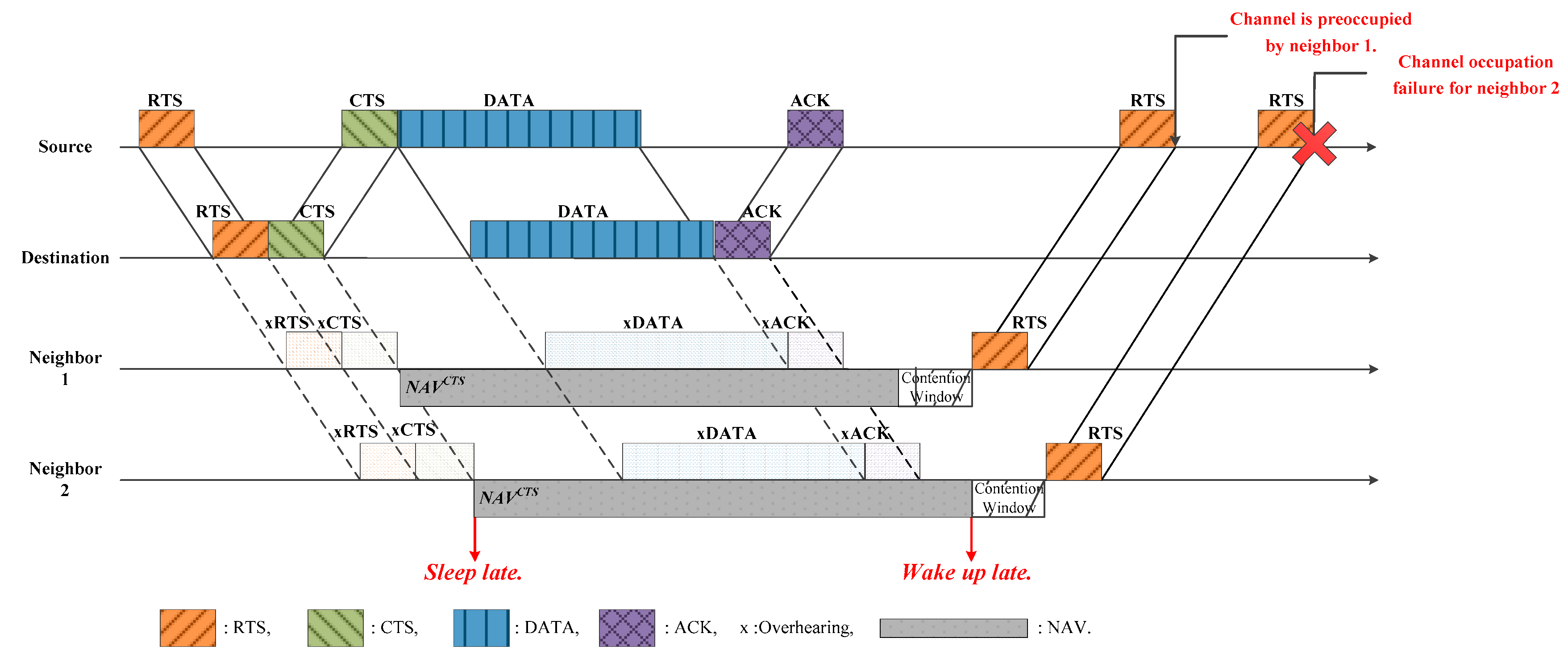
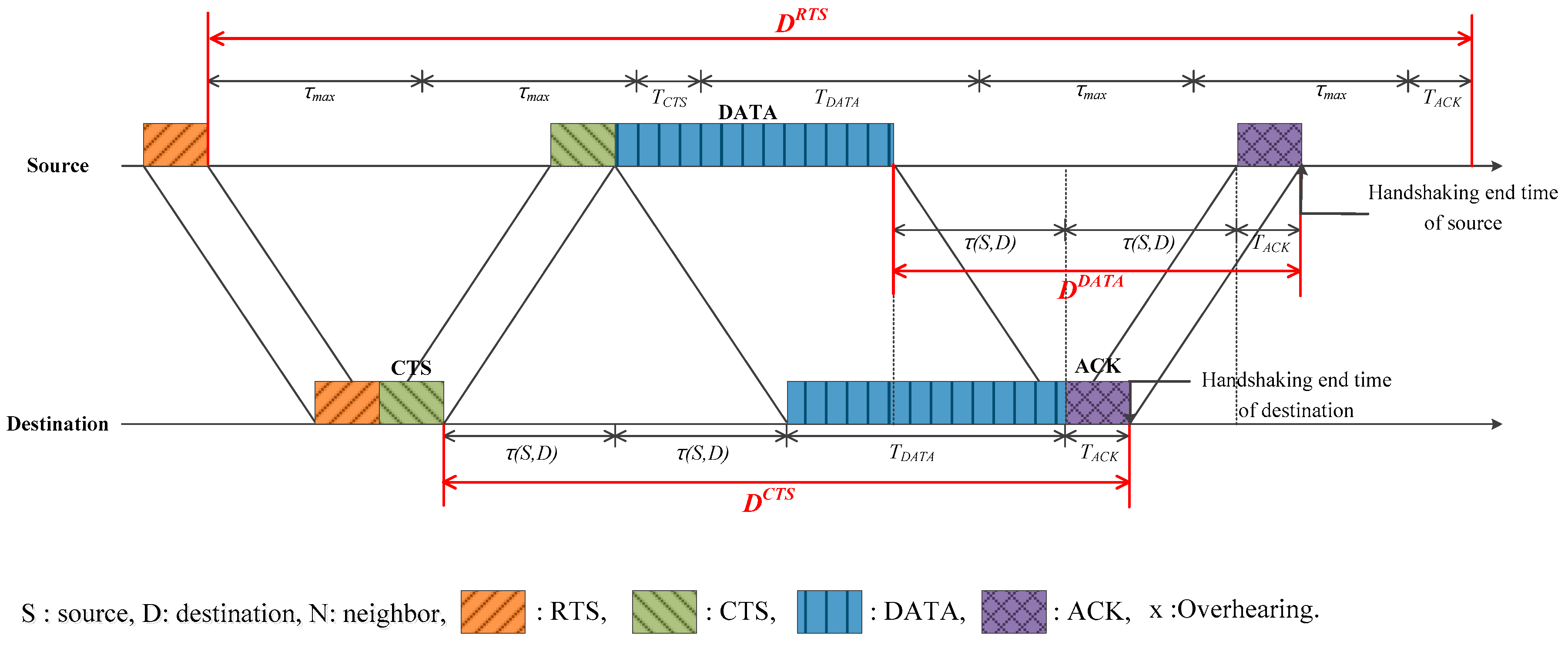
2. Problem Statement
3. Optimization of NAV
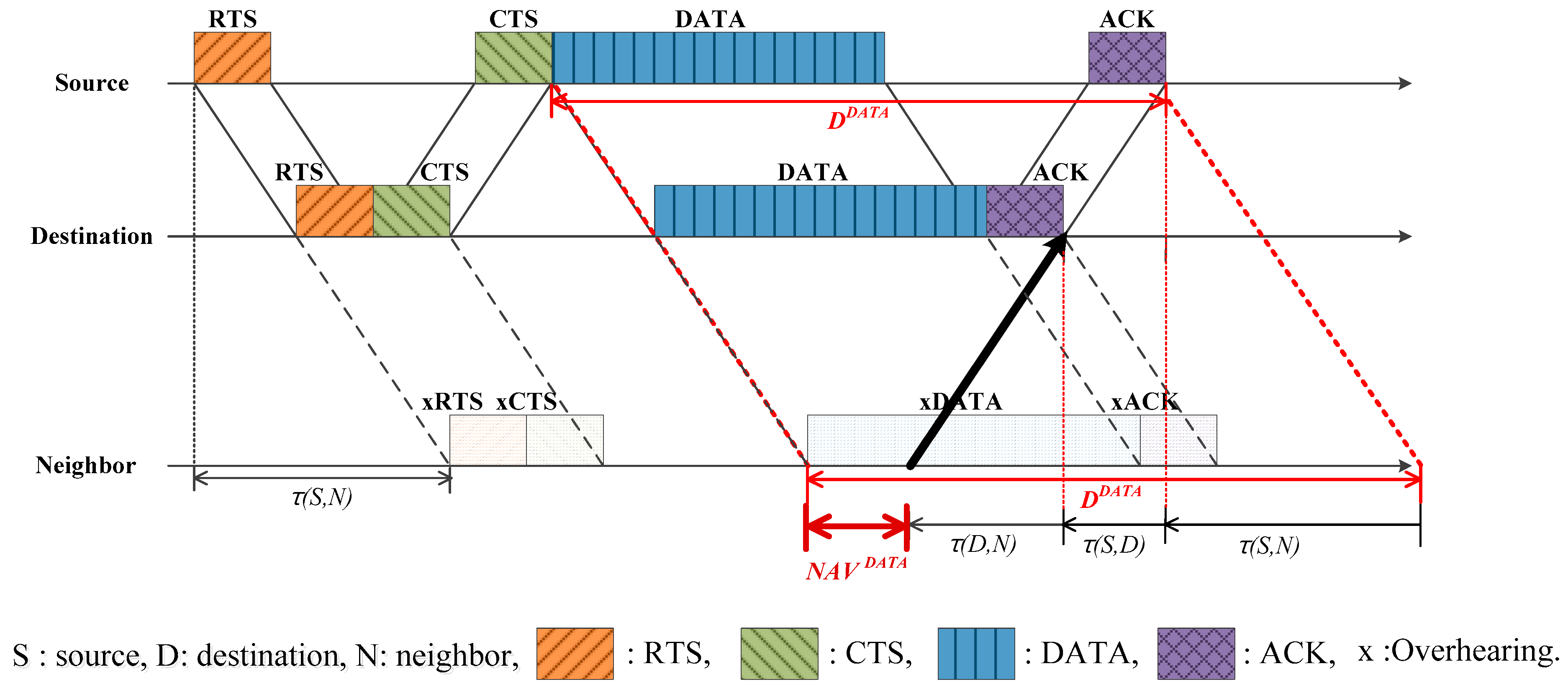
3.1. Trying to Communicate with Source
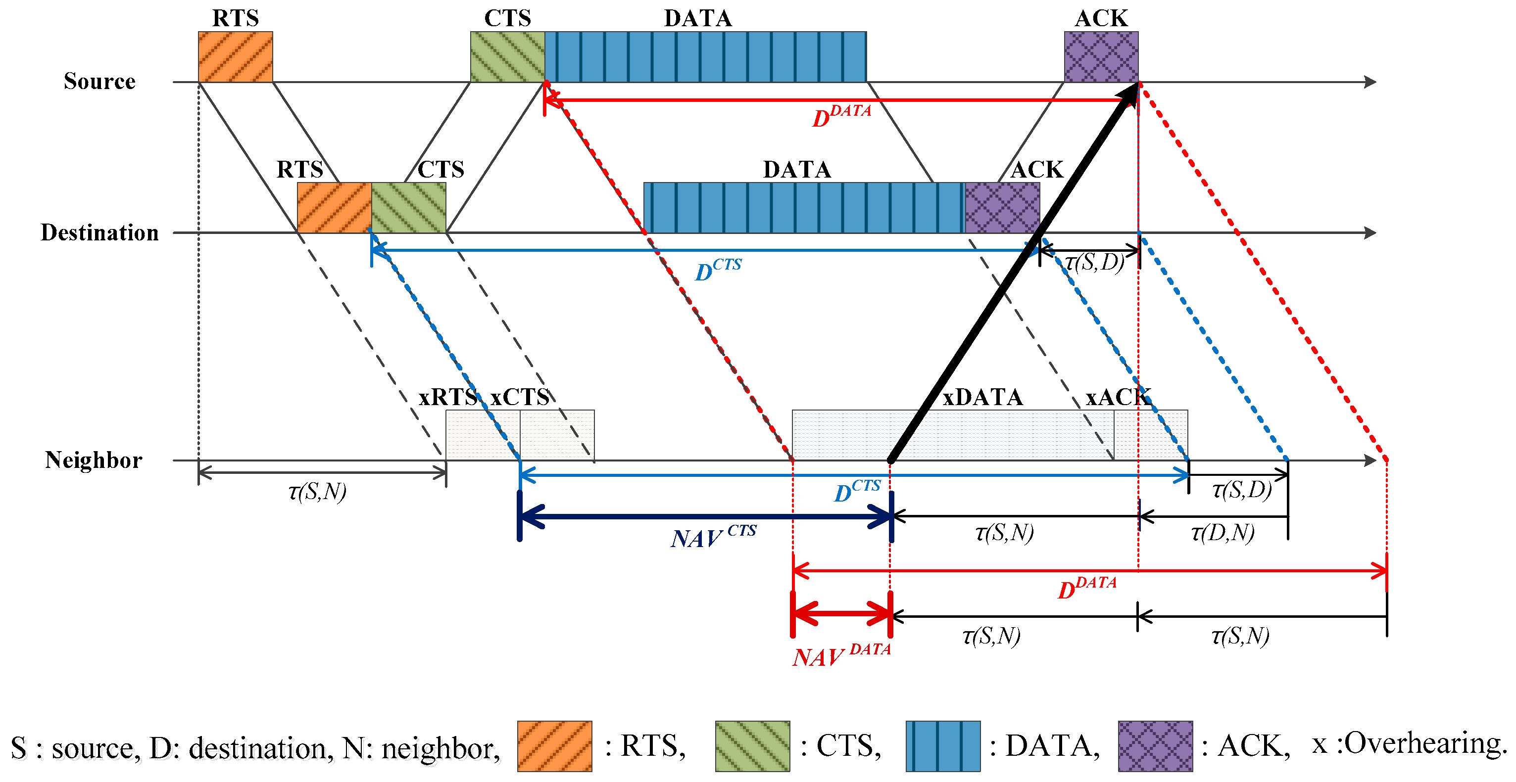
3.2. Trying to Communicate with the Destination
3.3. Trying to Communicate with Another Neighbor
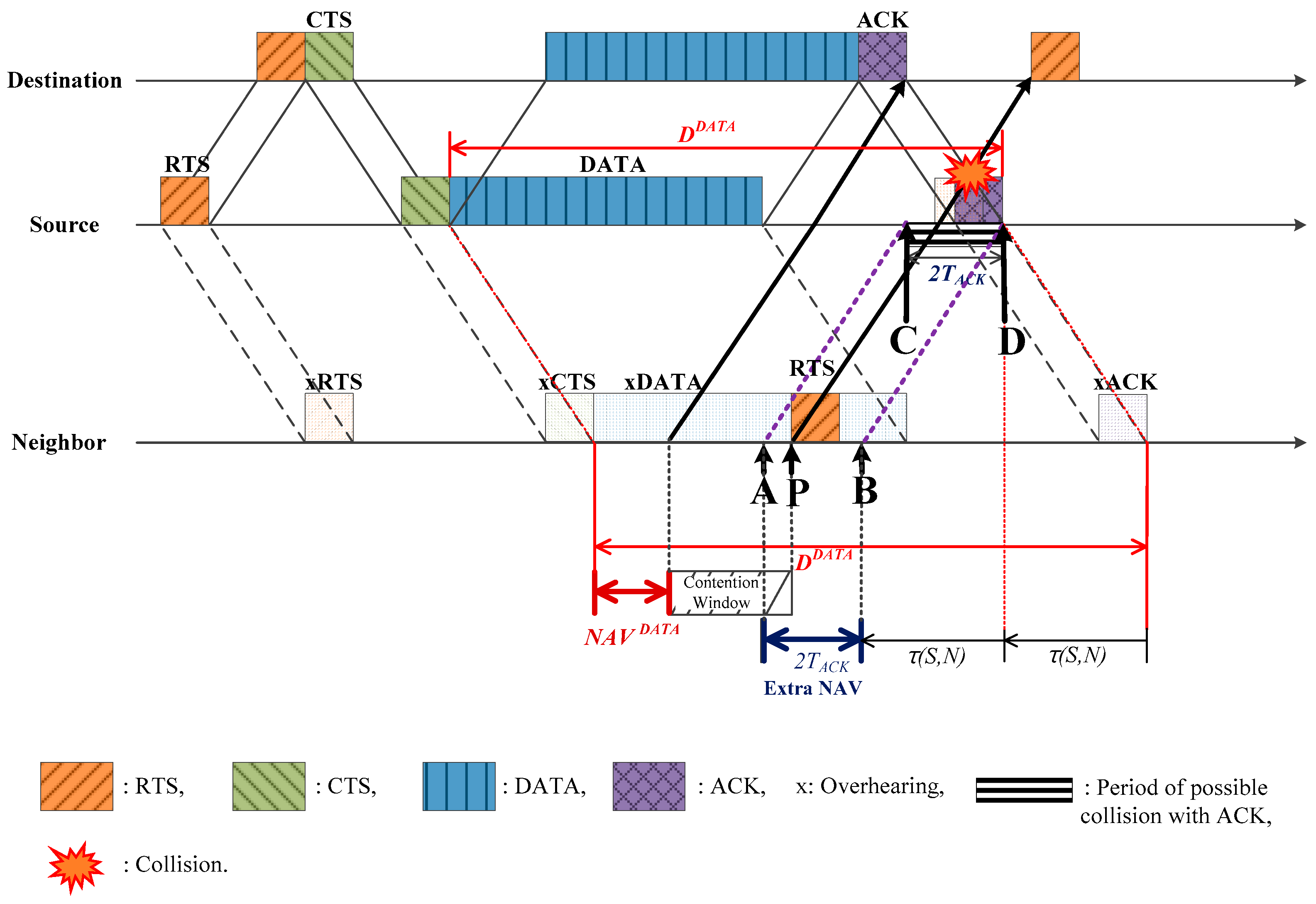
3.4. Extra NAV
4. Performance Analysis
4.1. Simulation Conditions
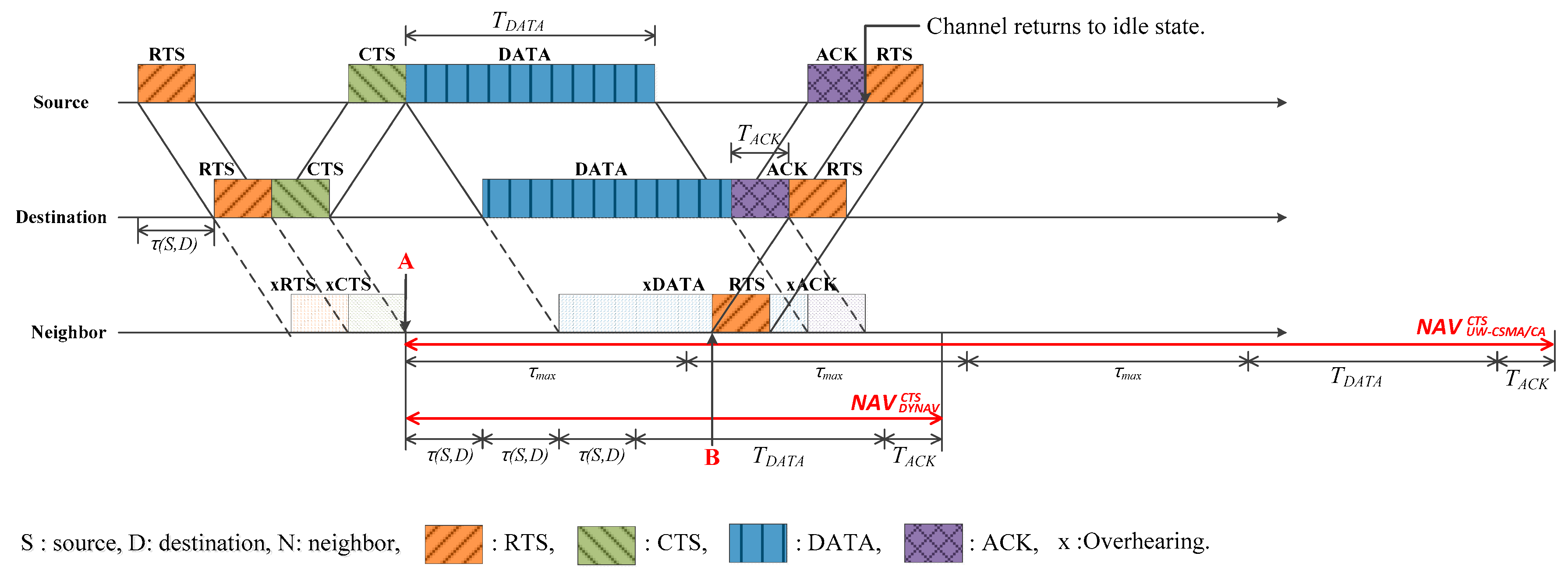
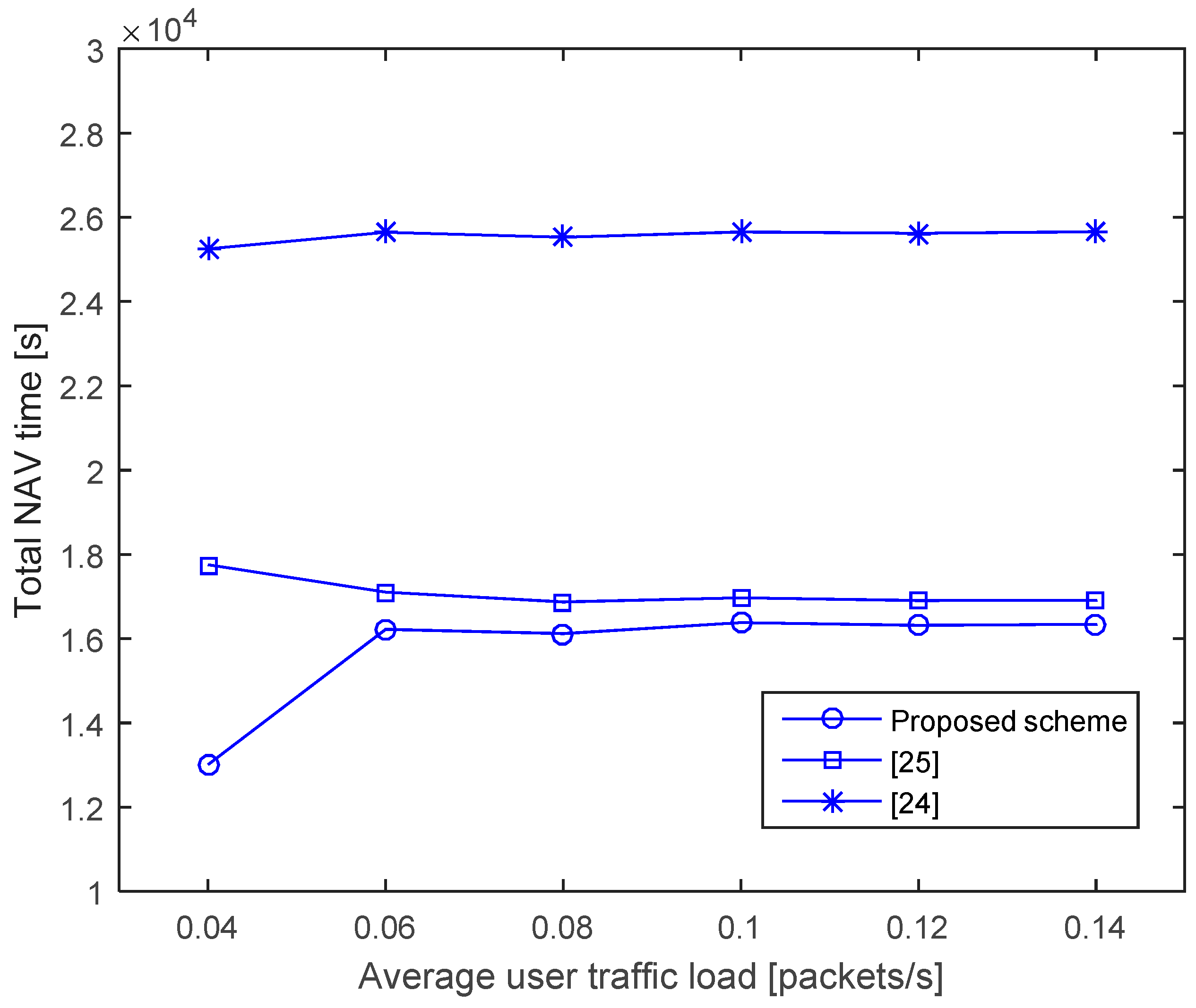
4.1.1. NAV Time
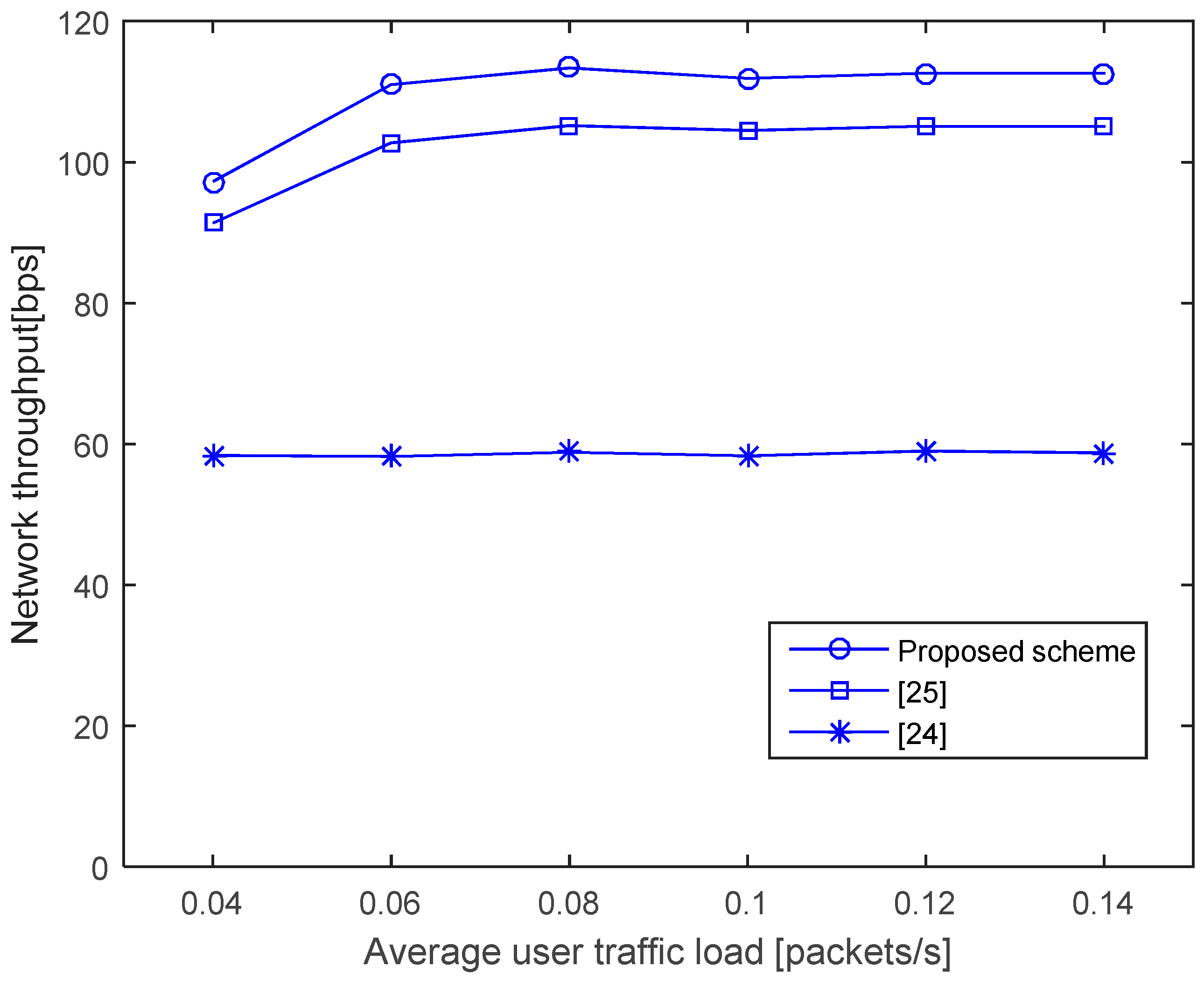
4.1.2. Throughput
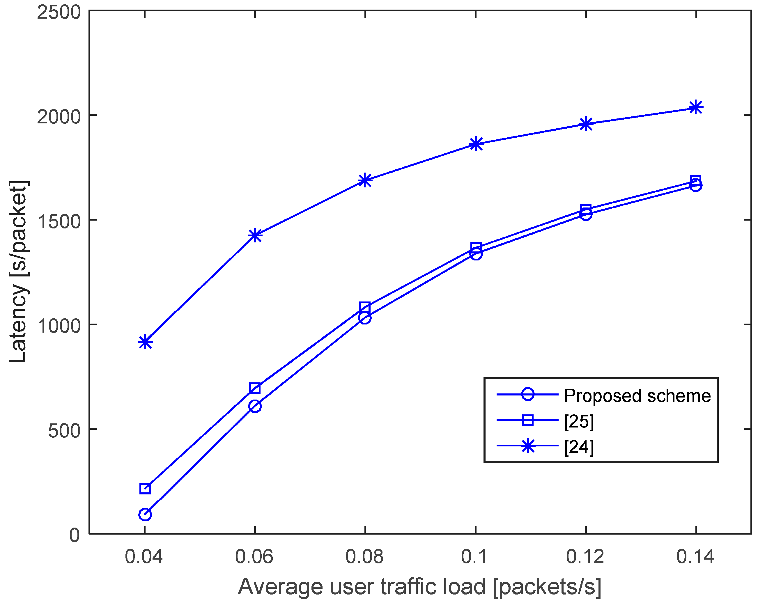
4.1.3. Latency
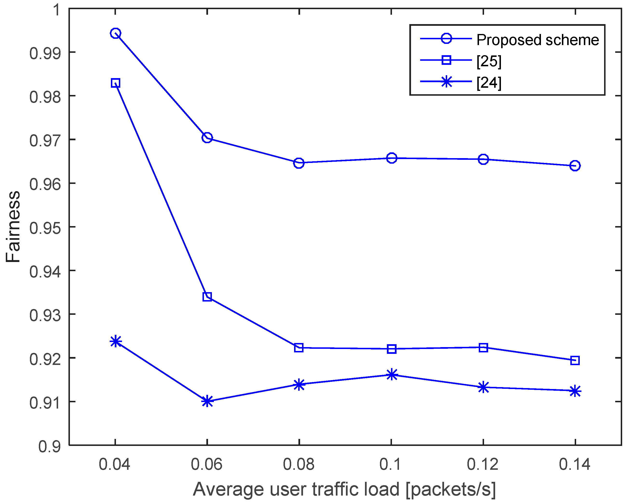
4.1.4. Fairness
5. Conclusions
Acknowledgments
Author Contributions
Conflicts of Interest
References
- Akyildiz, I.F.; Pompili, D.; Melodia, T. Underwater acoustic sensor networks: Research challenges. Ad Hoc Netw. 2005, 3, 257–279. [Google Scholar] [CrossRef]
- Stojanovic, M.; Preisig, J. Underwater acoustic communication channels: Propagation models and statistical characterization. IEEE Commun. Mag. 2009, 47, 84–89. [Google Scholar] [CrossRef]
- Stojanovic, M. On the Relationship between Capacity and Distance in an Underwater Acoustic Communication Channel. In Proceedings of the 1st ACM International Workshop on Underwater Networks, Los Angeles, CA, USA, 25 September 2006; pp. 41–47.
- Lurton, X. An Introduction to Underwater Acoustics: Principles and Applications; Springer-Praxis: London, UK, 2002. [Google Scholar]
- Casari, P.; Zorzi, M. Protocol design issues in underwater acoustic networks. Comput. Commun. 2011, 34, 2013–2025. [Google Scholar] [CrossRef]
- Vieira, L.F.M.; Kong, J.; Lee, U.; Gerla, M. Analysis of Aloha Protocols for Underwater Acoustic Sensor Networks. In Proceedings of the Aloha and Slot-ted Aloha Protocols for Underwater Sensor Networks, Los Angeles, CA, USA, 14 September 2006.
- Chirdchoo, N.; Soh, W.S.; Chua, K.C. ALOHA-based MAC Protocols with Collision Avoidance for Underwater Acoustic Networks. In Proceedings of the 26th IEEE International Conference on Computer Communications (INFOCOM), Anchorage, AK, USA, 6–12 May 2007; pp. 2271–2275.
- Park, M.K.; Rodoplu, V. UWAN-MAC: An energy-efficient mac protocol for underwater acoustic wireless sensor networks. IEEE J. Ocean. Eng. 2007, 32, 710–720. [Google Scholar] [CrossRef]
- Syed, A.A.; Ye, W.; Heidemann, J. T-Lohi: A New Class of MAC Protocols for Underwater Acoustic Sensor Networks. In Proceedings of the 27th Conference on Computer Communications INFOCOM 2008, Phoenix, AZ, USA, 13–18 April 2008; pp. 789–797.
- Climent, S.; Sanchez, A.; Capella, J.V.; Meratnia, N.; Serrano, J.J. Underwater acoustic wireless sensor networks: Advances and future trends in physical, MAC and routing layers. Sensors 2014, 14, 795–833. [Google Scholar] [CrossRef] [PubMed]
- Ng, H.-H.; Soh, W.-S.; Motani, M. MACA-U: A Media Access Protocol for Underwater Acoustic Networks. In Proceedings of the 2008 IEEE Global Telecommunication Globecom, New Orleans, LA, USA, 30 November–4 December 2008; pp. 1–5.
- Guo, X.; Frater, M.; Ryan, M. A Propagation-delay-tolerant Collision Avoidance Protocol for Underwater Acoustic Sensor Networks. In Proceedings of the OCEANS’06 Asia Pacific, Singapore, 16–19 May 2006; pp. 1–6.
- Guo, X.; Frater, M.R.; Ryan, M.J. Design of a propagation delay-tolerant MAC protocol for underwater acoustic sensor networks. IEEE J. Ocean. Eng. 2009, 34, 170–180. [Google Scholar]
- Chirdchoo, N.; Soh, W.-S.; Chua, K.-C. RIPT: A Receiver-initiated Reservation- based Protocol for Underwater Acoustic Networks. IEEE J. Sel. Areas Commun. 2008, 26, 1744–1753. [Google Scholar] [CrossRef]
- Noh, Y.; Wang, P.; Uichin, L.; Torres, D.; Gerla, M. DOTS: A Propagation Delay-aware Opportunistic MAC Protocol for Underwater Sensor Networks. In Proceedings of the 2010 18th IEEE International Conference on Network Protocols (ICNP), Kyoto, Japan, 5–8 October 2010; pp. 183–192.
- Chen, Y.-D.; Liu, S.-S.; Chang, C.-M.; Shih, K.-P. CS-MAC: A Channel Stealing MAC Protocol for Improving Bandwidth Utilization in Underwater Wireless Acoustic Networks. In Proceedings of the OCEANS 2011, Kona, HI, USA, 19–22 September 2011; pp. 1–5.
- Xie, P.; Cui, J.H. R-MAC: An Energy-Efficient MAC Protocol for Underwater Sensor Networks. In Proceedings of the International Conference on Wireless Algorithms, Systems and Applications IEEE WASA’07, Chicago, IL, USA, 1–3 August 2011; pp. 187–198.
- Ng, H.-H.; Soh, W.-S.; Motani, M. ROPA: A MAC Protocol for Underwater Acoustic Networks with Reverse Opportunistic Packet Appending. In Proceedings of the 2010 Wireless Communications and Networking Conference (WCNC), Sydney, Australia, 18–21 April 2010; pp. 1–6.
- Liao, W.H.; Huang, C.C. SF-MAC: A spatially fair mac protocol for underwater acoustic sensor networks. IEEE Sens. J. 2012, 12, 1686–1694. [Google Scholar] [CrossRef]
- Fullmer, C.L.; Garcia-Luna-Aceves, J.J. Floor acquisition multiple access (FAMA) for packet-radio networks. SIGCOMM Comput. Commun. Rev. 1995, 25, 262–273. [Google Scholar] [CrossRef]
- Peng, Z.; Zhou, Z.; Guo, Z.; Cui, J.H. COPE-MAC: A Contention-Based Medium Access Control Protocol with Parallel Reservation for Underwater Acoustic Networks. In Proceedings of the OCEANS 2010, Sydney, Australia, 24–27 May 2010; pp. 1–10.
- Lee, J.-W.; Cho, H.-S. Cascading multi-hop reservation and transmission in underwater acoustic sensor networks. Sensors 2014, 14, 18390–18409. [Google Scholar] [CrossRef] [PubMed]
- Lee, J.-W.; Cho, H.-S. A hybrid sender- and receiver-initiated protocol scheme in underwater acoustic sensor networks. Sensors 2015, 15, 28052–28069. [Google Scholar] [CrossRef] [PubMed]
- Shin, D.-S.; Kim, D.-K. A dynamic NAV determination protocol in 802. In 11 based underwater networks. In Proceedings of the IEEE International Symposium on Wireless Communication Systems, Reykjavik, Iceland, 21–24 October 2008; pp. 401–405.
- Fang, D.; Li, Y.; Huang, H.; Yin, L. A CSMA/CA-Based MAC Protocol for Underwater Acoustic Networks. In Proceedings of the 6th International Conference on Wireless Communications Networking and Mobile Computing (WiCOM), Chengdu, China, 23–25 September 2010; pp. 1–4.
- LAN/MAN (IEEE 802) Standards Committee. Wireless LAN Media Access Control (MAC) and Physical Layer (PHY) Specifications; IEEE: New York, NY, USA, 1999. [Google Scholar]
- Heidemann, J.; Stojanovic, M.; Zorzi, M. Underwater sensor networks: Applications, advances and challenges. Philos. Trans. R. Soc. A 2012, 370, 158–175. [Google Scholar] [CrossRef] [PubMed]
- Ahn, J.; Syed, A.; Krishnamachari, B.; Heidemann, J. Design and analysis of a propagation delay tolerant ALOHA protocol for underwater networks. Ad Hoc Netw. 2011, 9, 752–766. [Google Scholar] [CrossRef]
- Lee, J.-W.; Kim, J.-P.; Lee, J.-H.; Jang, Y.S.; Dho, K.C.; Son, K.; Cho, H.-S. An Improved ARQ Scheme in Underwater Acoustic Sensor Networks. In Proceedings of the MTS/IEEE Kobe Techno-Ocean—OCEANS’08, Kobe, Japan, 8–11 April 2008; pp. 1–5.
- Lee, J.-W.; Cheon, J.; Cho, H.-S. A Cooperative ARQ Scheme in Underwater Acoustic Sensor Networks. In Proceedings of the OCEANS 2010, Sydney, Australia, 24–27 May 2010; pp. 1–5.
- Kwon, J.K.; Seo, B.-M.; Yun, K.; Cho, H.-S. Time-efficient high-rate data flooding in one-dimensional acoustic underwater sensor networks. Sensors 2015, 15, 27671–27691. [Google Scholar] [CrossRef] [PubMed]
- Khan, J.U.; Cho, H.-S. A distributed data-gathering protocol using AUV in underwater sensor networks. Sensors 2015, 15, 19331–19350. [Google Scholar] [CrossRef] [PubMed]
- Ghosh, A.; Lee, J.-W.; Cho, H.-S. Throughput and energy efficiency of a cooperative hybrid ARQ protocol for underwater acoustic sensor networks. Sensors 2013, 13, 15385–15408. [Google Scholar] [CrossRef] [PubMed]
- Khan, J.U.; Cho, H.-S. Data-gathering scheme using AUVS in large-scale underwater sensor networks: A multihop approach. Sensors 2016, 16, 1626. [Google Scholar] [CrossRef] [PubMed]
- Brekhovskikh, L.M.; Lysanov, Y.P. Fundamentals of Ocean Acoustics, 3rd ed.; Springer: New York, NY, USA, 2003. [Google Scholar]
- Sozer, E.M.; Stojanovic, M.; Proakis, J.G. Underwater acoustic networks. IEEE J. Ocean. Eng. 2000, 25, 72–83. [Google Scholar] [CrossRef]
- Jain, R.; Chiu, D.; Hawe, W. A Quantitative Measure of Fairness and Discrimination for Resource Allocation in Shared Computer Systems; Eastern Research Laboratory, Digital Equipment Corporation: Hudson, MA, USA, 1984. [Google Scholar]


| Parameters | Value |
|---|---|
| Network dimensions | 3 km × 3 km |
| Propagation speed | 1500 m/s |
| Node transmission range | 500 m |
| Data rate | 1 kbps |
| Contention window size | 15–1023 (binary exponential back-off) |
© 2016 by the authors; licensee MDPI, Basel, Switzerland. This article is an open access article distributed under the terms and conditions of the Creative Commons Attribution (CC-BY) license (http://creativecommons.org/licenses/by/4.0/).
Share and Cite
Cho, J.; Shitiri, E.; Cho, H.-S. Network Allocation Vector (NAV) Optimization for Underwater Handshaking-Based Protocols. Sensors 2017, 17, 32. https://doi.org/10.3390/s17010032
Cho J, Shitiri E, Cho H-S. Network Allocation Vector (NAV) Optimization for Underwater Handshaking-Based Protocols. Sensors. 2017; 17(1):32. https://doi.org/10.3390/s17010032
Chicago/Turabian StyleCho, Junho, Ethungshan Shitiri, and Ho-Shin Cho. 2017. "Network Allocation Vector (NAV) Optimization for Underwater Handshaking-Based Protocols" Sensors 17, no. 1: 32. https://doi.org/10.3390/s17010032