
Easy Handling of Sensors and Actuators over TCP/IP Networks by Open Source Hardware/Software

 , and
, and 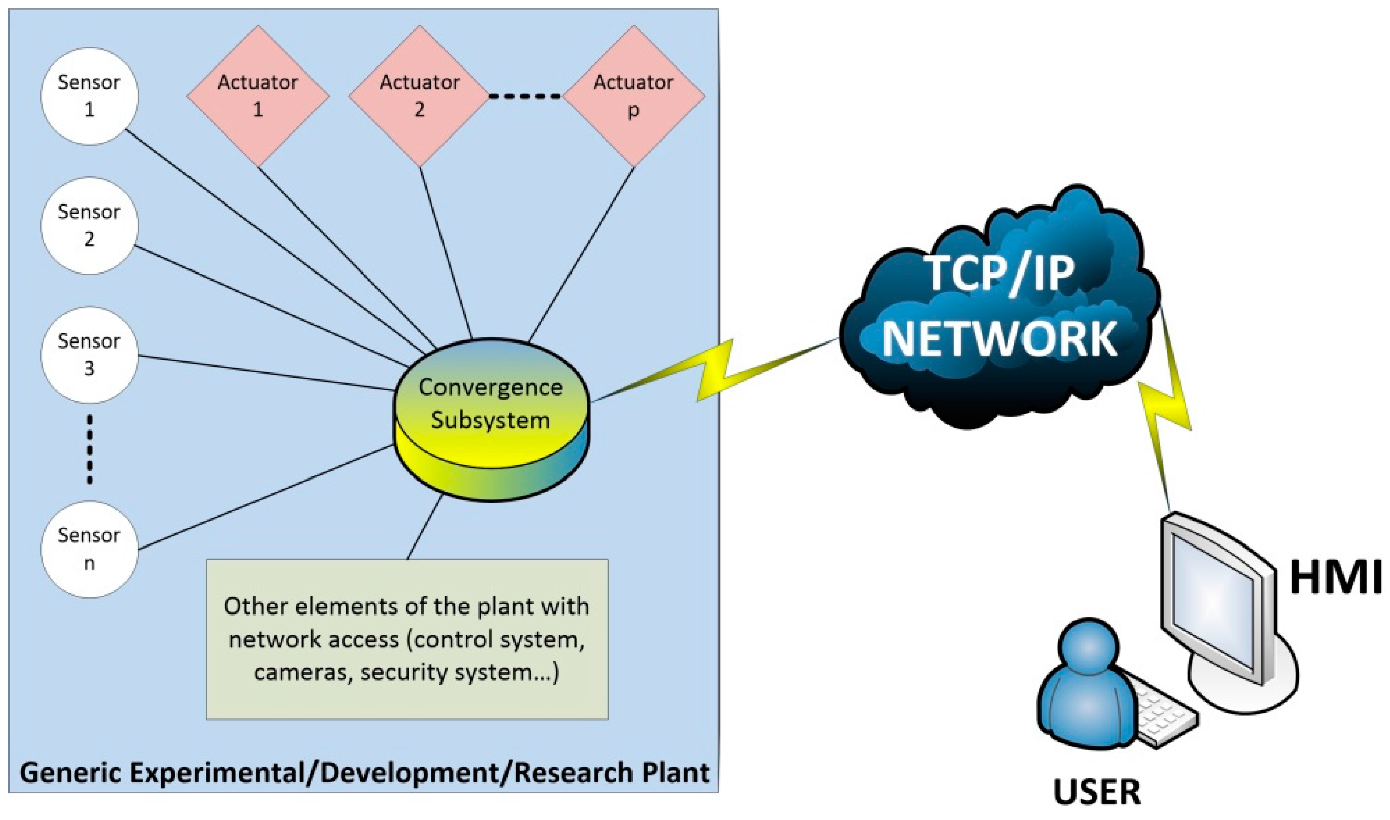
Abstract
:1. Introduction
2. System Overview
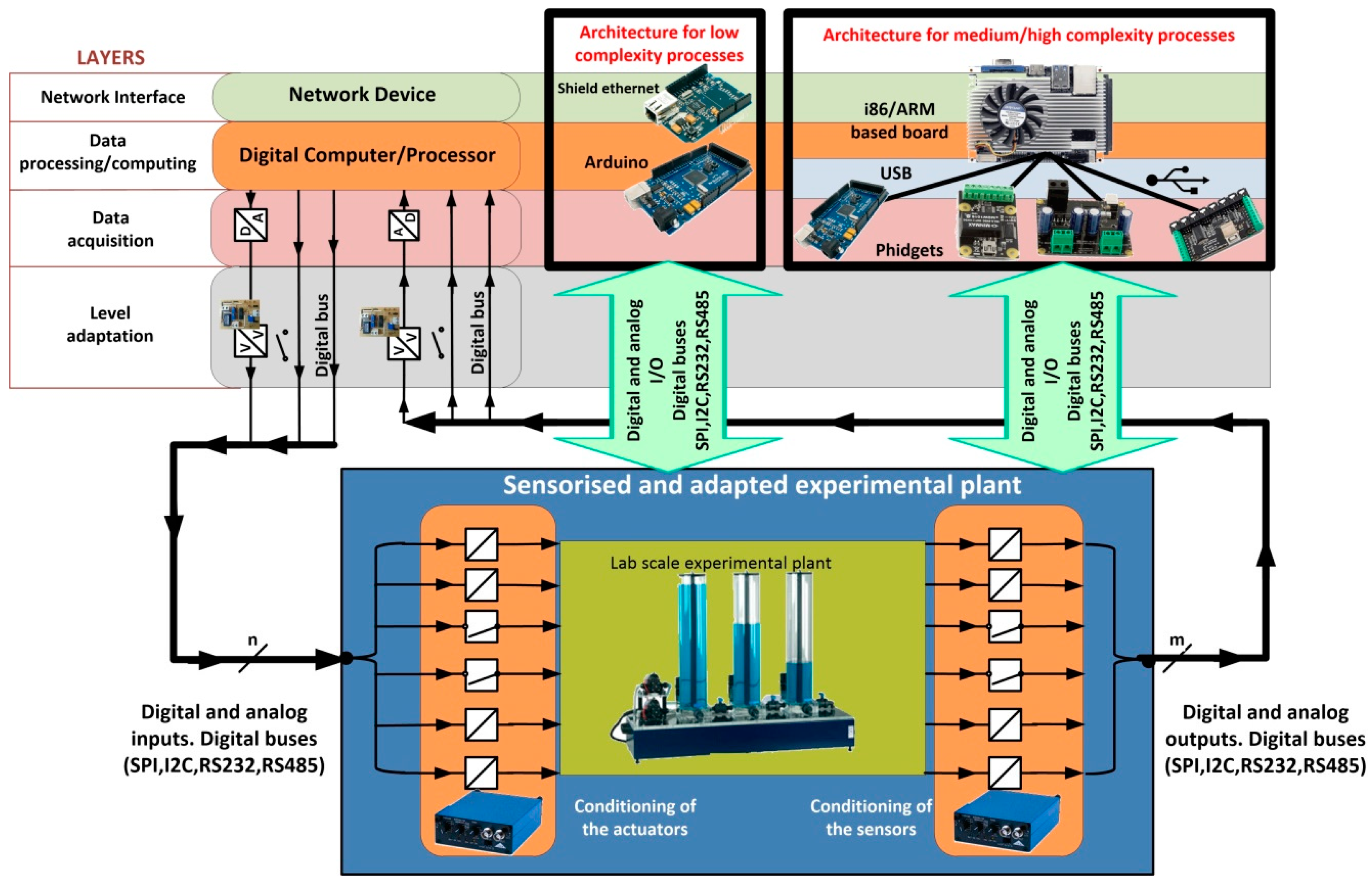
3. The Convergence Subsystem
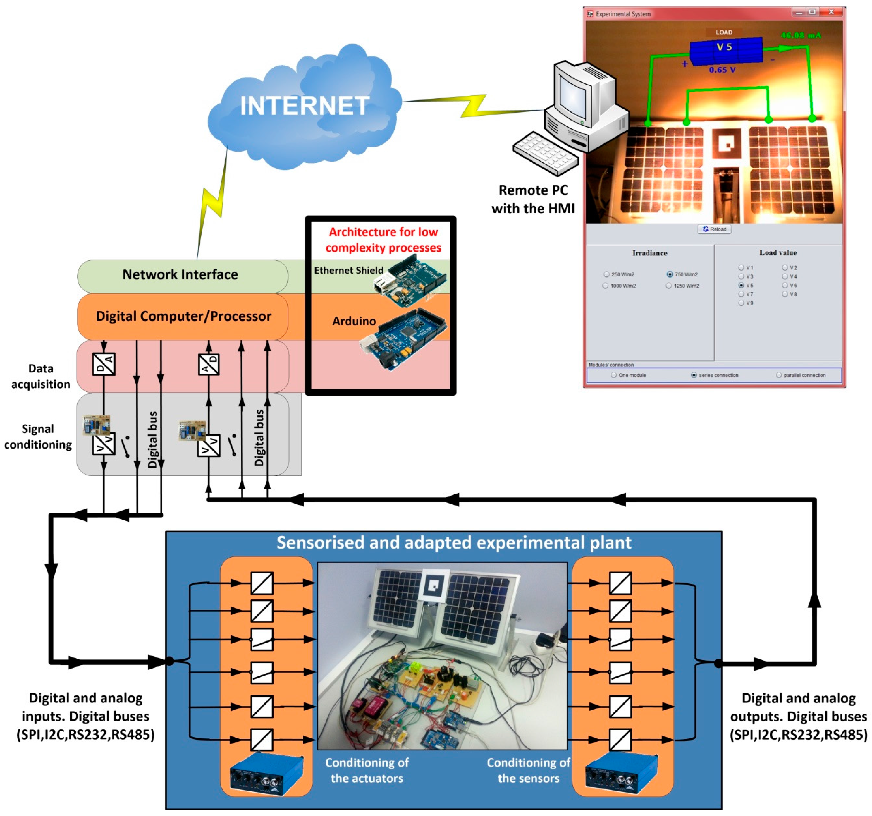
- The network interface, that is, the layer that provides access to a TCP/IP network.
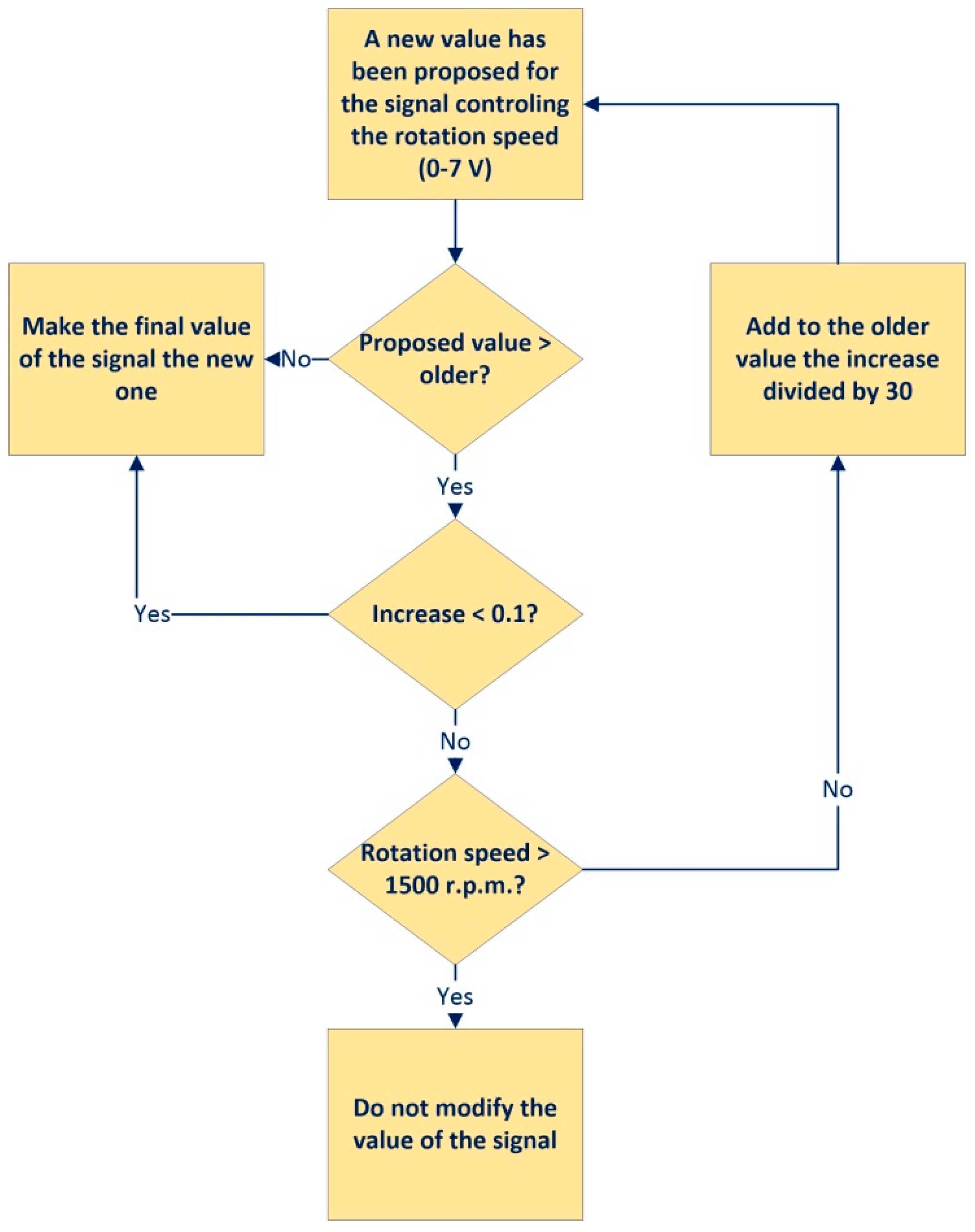
- The layer of data processing/computing. It provides: TPC/IP protocol, the capability of processing to allow the establishment of network communications, and the capability of data computing. This layer also establishes the indispensable safety actions. An example of a safety action is to prevent overspeeding of an electric machine or its overheating.
- The data acquisition layer. This one provides the interface which allows the layer of data processing/computing to receive and send the information required for following the process evolution. In fact, input and output signals should be adapted according to the characteristics of the Data Acquisition System (DAQ), which should enable the processing of signals with the most common values. In addition, the DAQ usually allows digital inputs and outputs buses, such as RS232, I2C, SPI and DALLAS, among others.
- Finally, the layer of level adaptation has been introduced. Indeed, the digital and analog outputs to be processed from the plant by the DAQ need to be properly conditioned—amplification, filtering, linearization, optocoupling. This is the mission of this layer.
- Generality. It consists of using components with scalability and modularity. Thus, the proposed solution is adapted to plants with different data processing needs.
- Economic viability. It consists of using open hardware platforms and open source software.
- Easy design. The designer does not have to be trained on advanced knowledge in communications and electronics neither programming expertise.
- Rapid development and deployment. Due to the previous features, the time devoted to develop and implement the convergence subsystem is reduced.
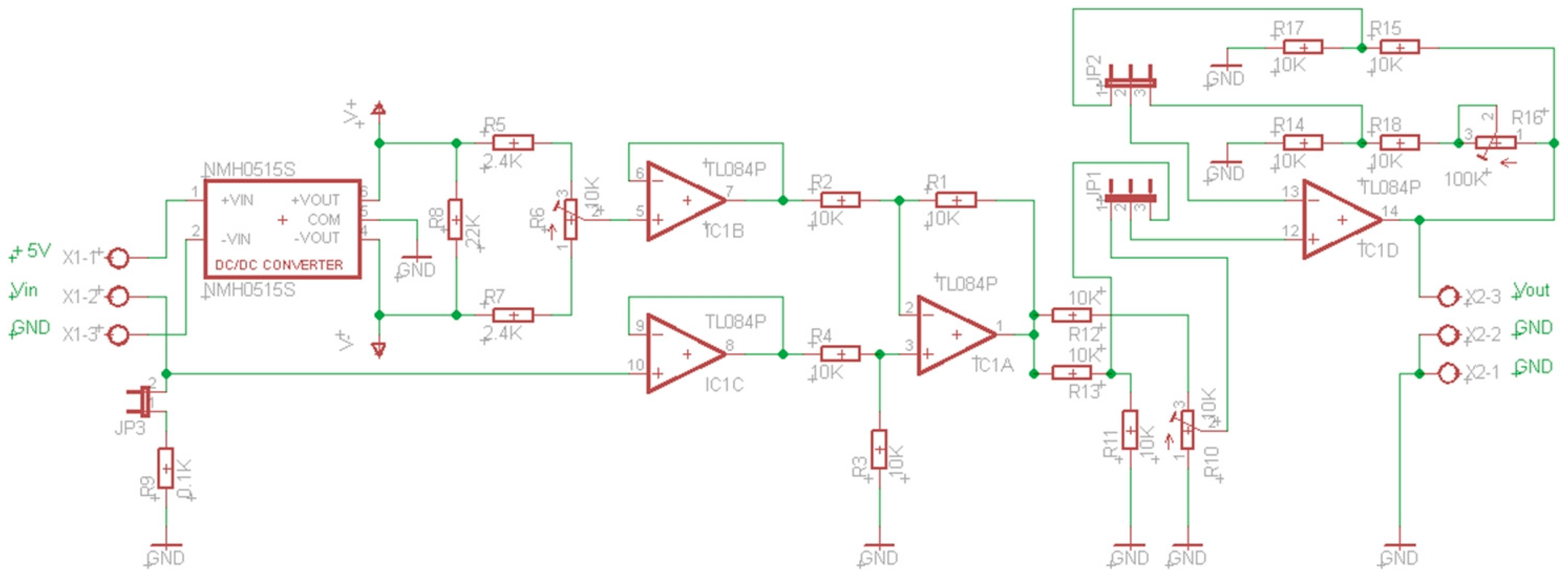
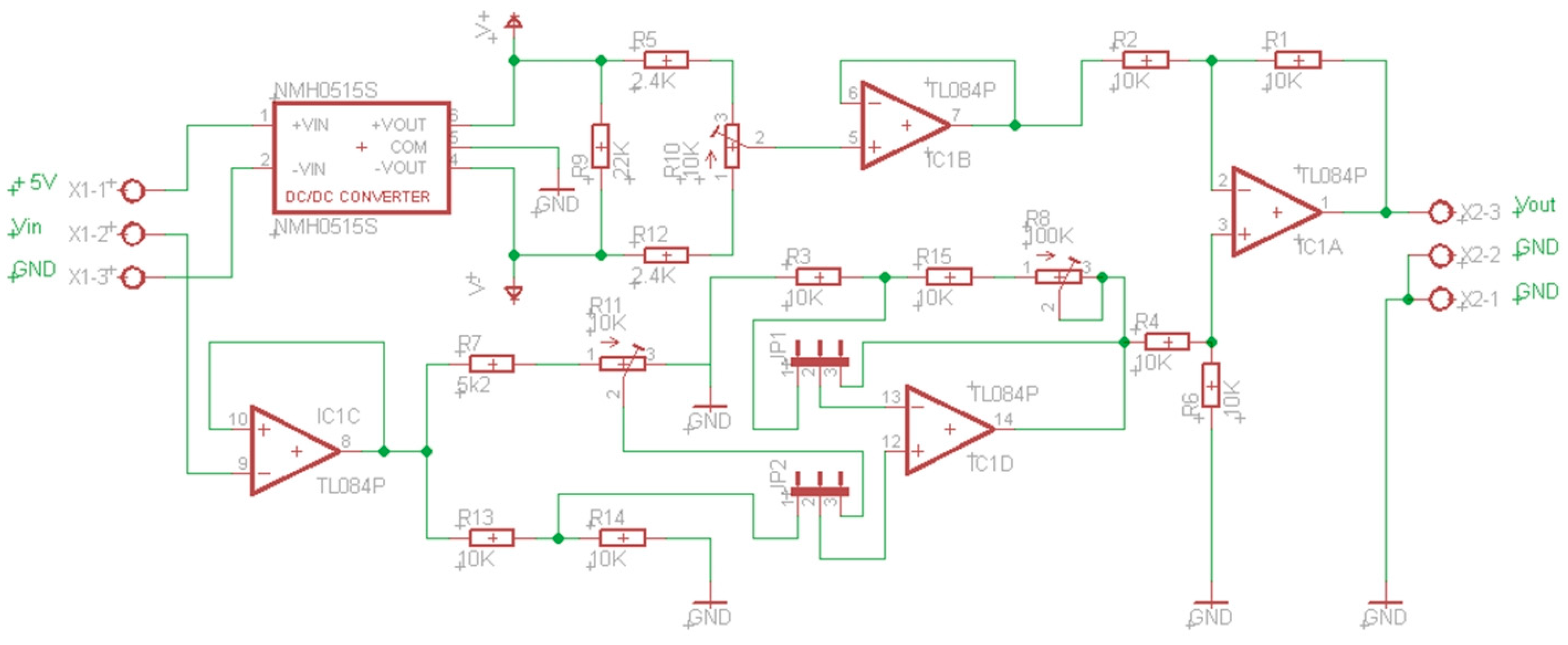
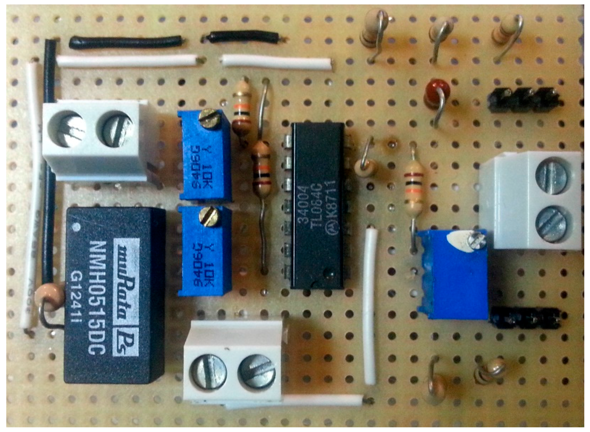
3.1. Layer of Level Adaptation
3.2. Architecture for Processes with Low Complexity
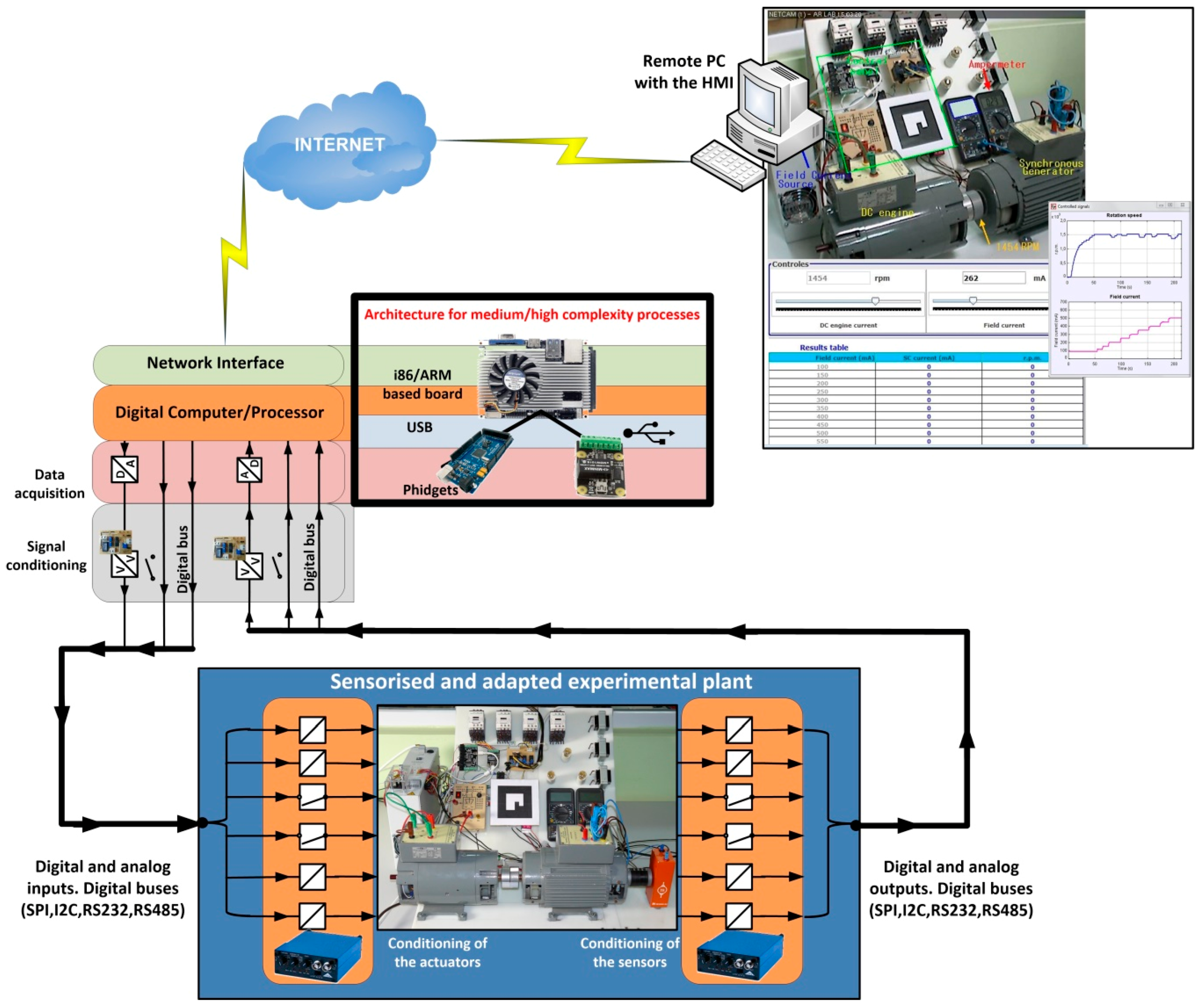
3.3. Architecture for Processes with Medium/High Complexity
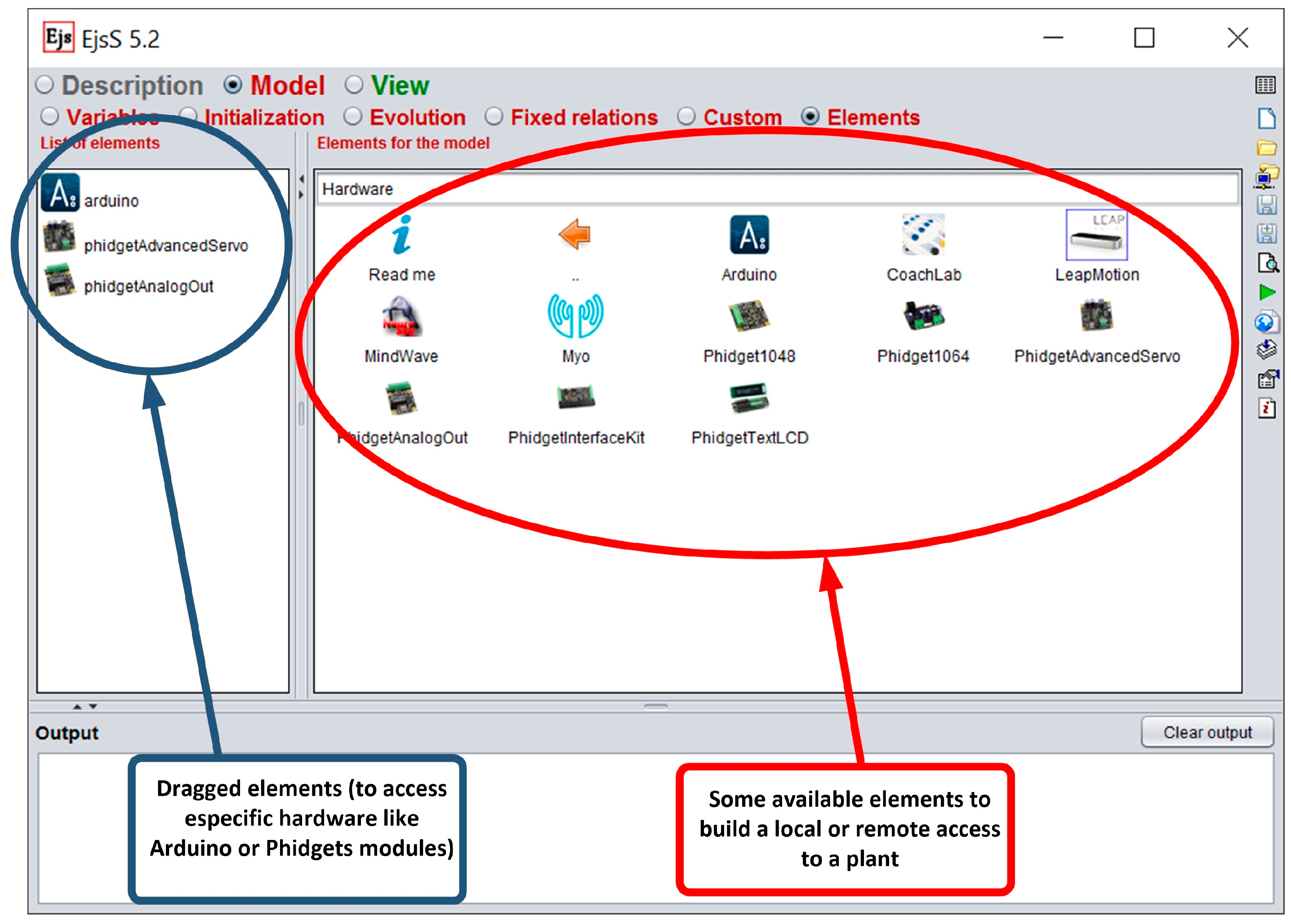
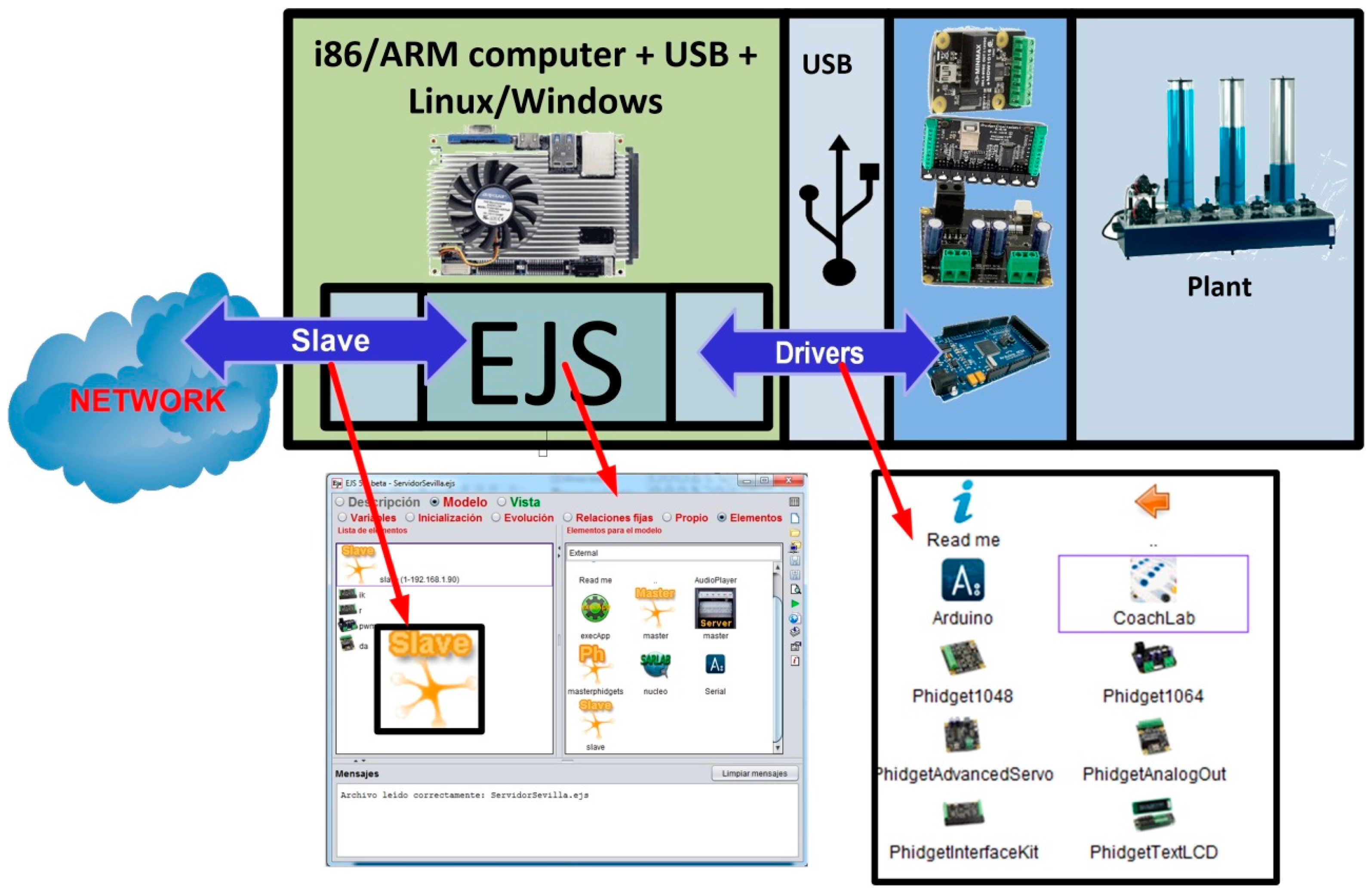
3.4. Software of the Convergence Subsystem
- Communications between the convergence subsystem and the user interface.
- Control of the process behavior.
- Process safety.
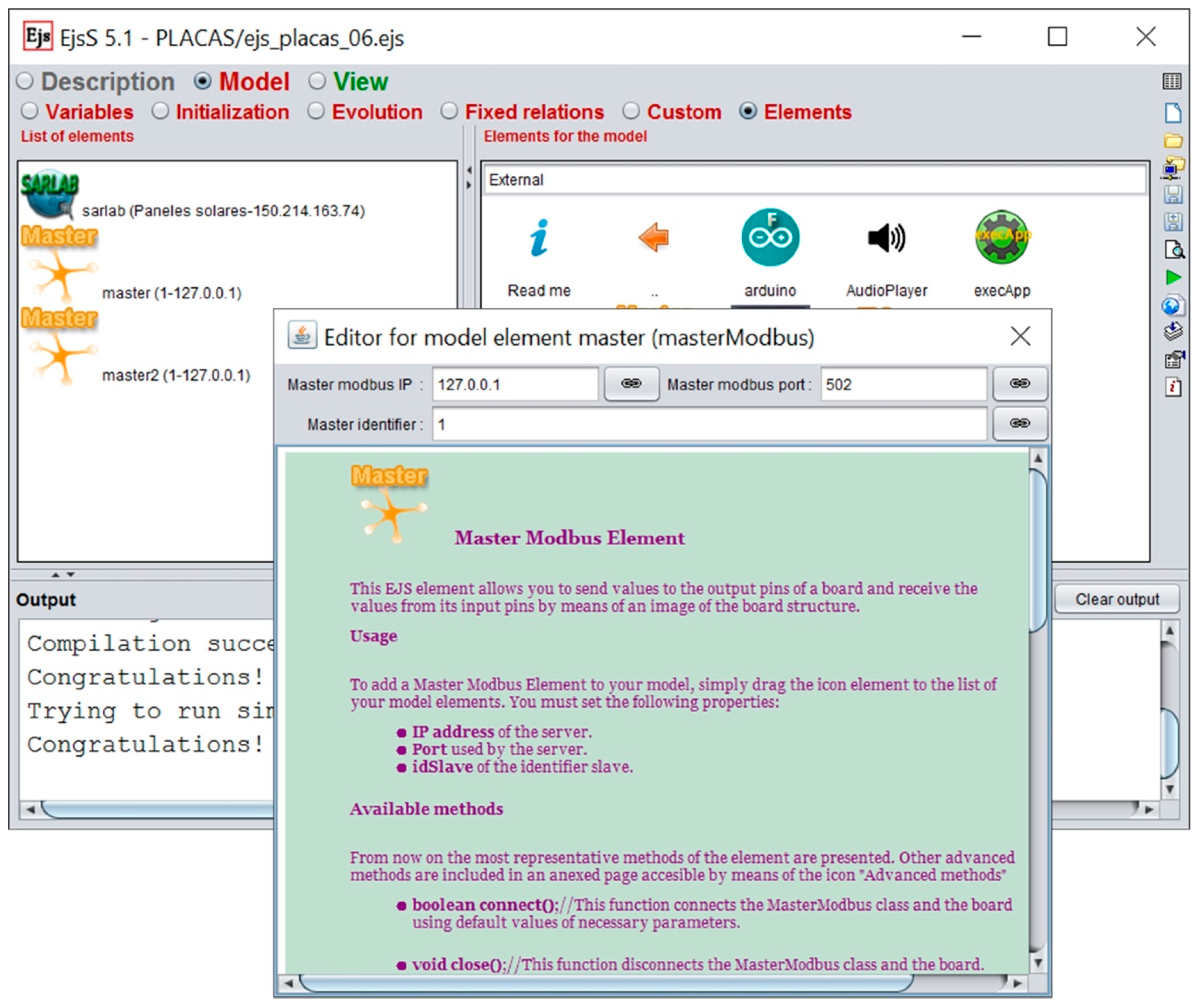
4. Unification of Communications Using the Industrial Modbus Protocol
- IP address of the server.
- Port used by the server.
- Identifier for the slave.
- Within a master-slave model and in a communications unified scenario, all the elements can connect to any other element. On the contrary, the connection of all the elements is very difficult to achieve with several designers of client-server structures working independently.
- M2M (machine to machine) applications can be used to make the corresponding connections between the plant components (topological control).
- The implementation becomes easier because the communications are developed in the same way in all of the plants components.
- Different industrial components such as PLCs, digital controllers, etc., that support standard Modbus communication can be used in the plants.
- Monitoring software can be easily integrated in the system.
- There are simulators that allow the developed applications to be debugged.
- The development of the communications application is performed at a high level.
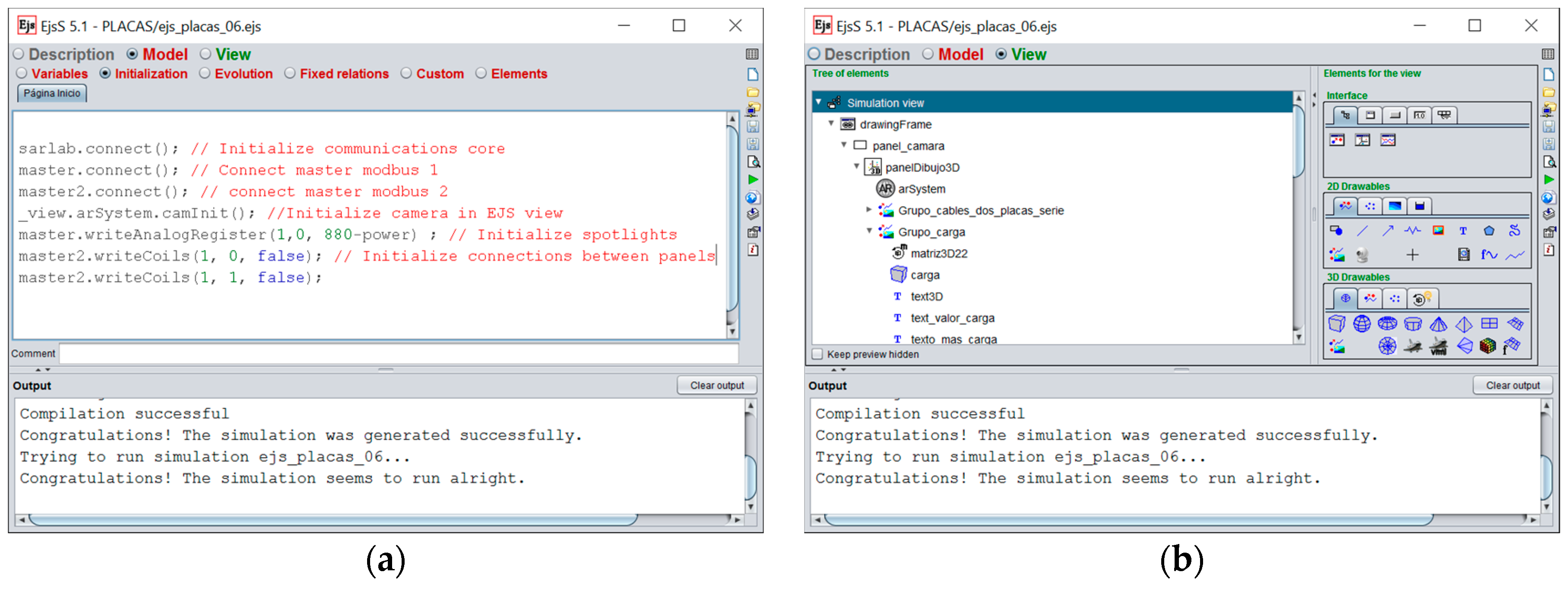
- connect(): open the connection to the master. If the name of the master is, for example, myMaster, the user only needs to write myMaster.connect() to access the master. Other methods are specified in the same way.
- writeCoil(int slaveId, int index, boolean value): write a boolean value to a specific slave in index position.
- writeAnalogRegister(int SlaveId, int index, int value): write an analog value to a specific slave in index position.
- close(): close the connection to the master.
- monitorInit(): This function creates a graphical monitor to make easiest the test of all the functions calls included in the Master Modbus element.
- etc.
5. Results
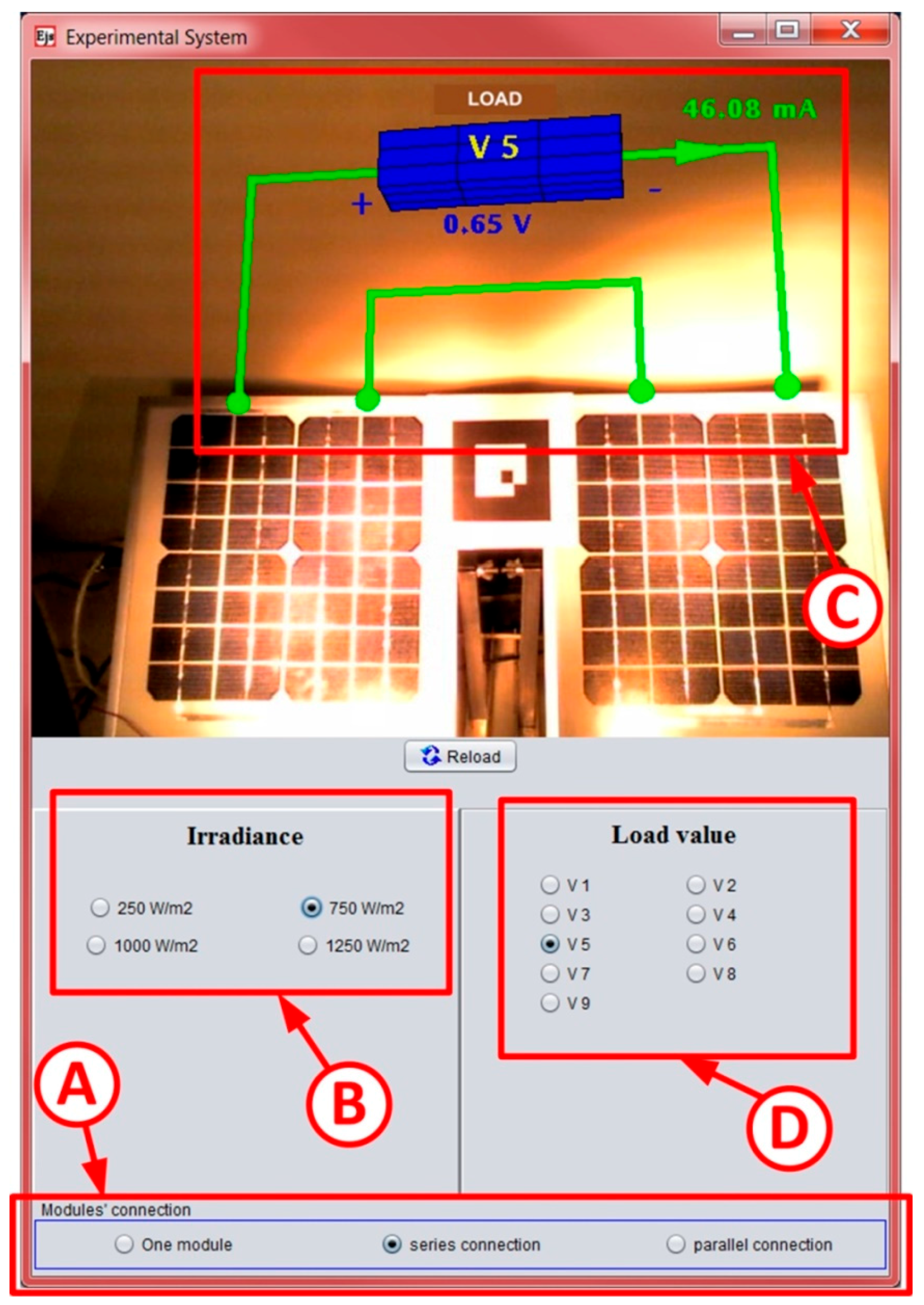
5.1. A Use Case of a Process with Low Complexity
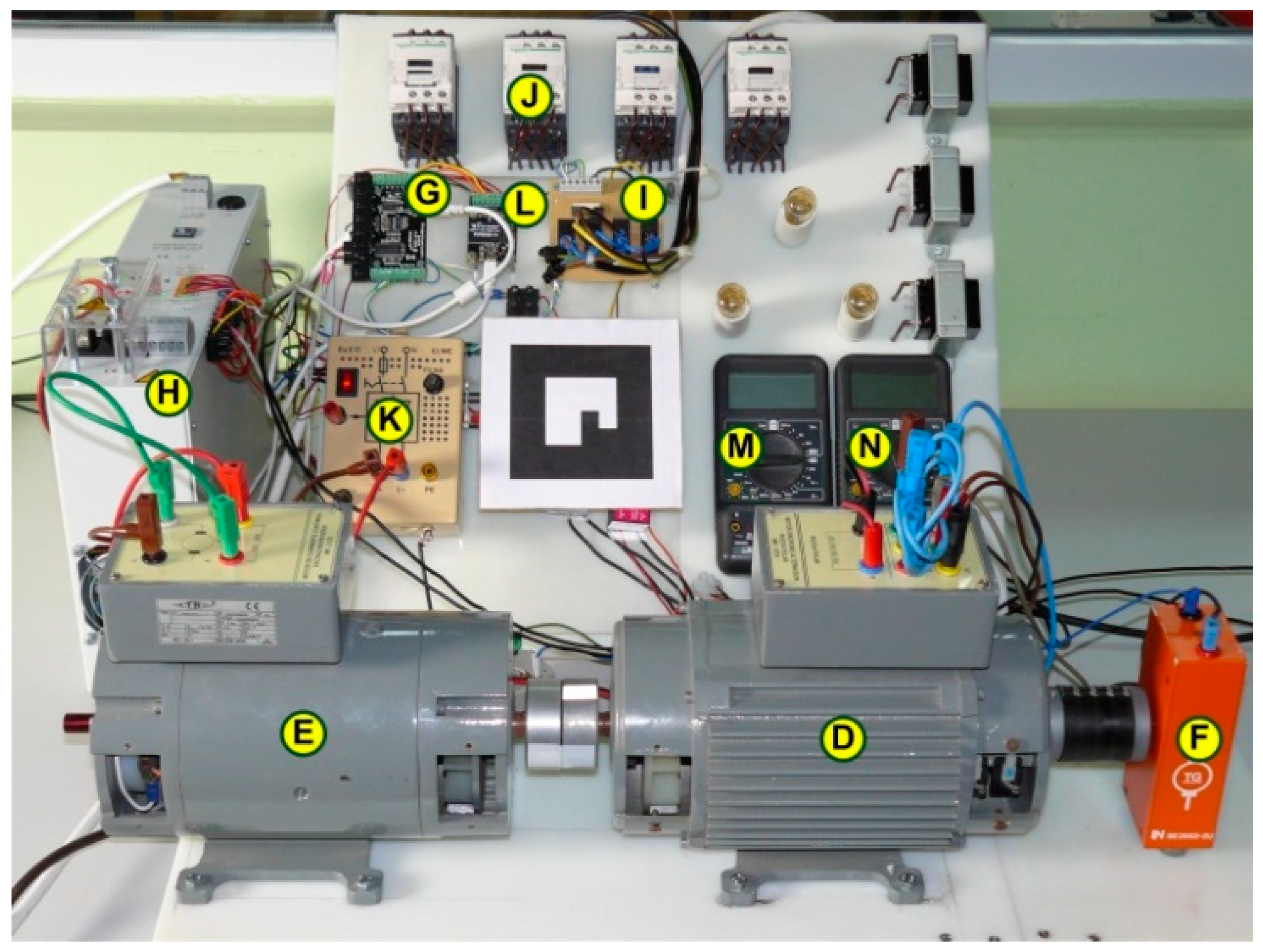
5.2. A Use Case of a Process with Medium Complexity
- -
- Measurement of the rotation speed.
- -
- Measurement of the field current from the current source which supplies it, item H.
- -
- Switching on/off current source H.
- -
- Turning on/off the plant supply, according to the instructions received from the ARM board, through a set of optocoupled relays, item I.
- -
- Configuring the connections suitable for each test of the synchronous generator, through a relay, item J.
6. Conclusions
Author Contributions
Conflicts of Interest
Abbreviations
| CPS | Cyber-Physical System |
| DAQ | Data Acquisition System |
| EJS | Easy Java/JavaScript Simulations |
| HMI | Human Machine Interface |
| I2C | Inter-Integrated Circuit |
| ICT | Information and Communication Technologies |
| IDE | Integrated Development Environment |
| IoT | Internet of Things |
| IPv6 | Internet Protocol version 6 |
| LAN | Local Area Network |
| M2M | Machine to Machine |
| MCLAL | Mapping Circuit of Level Adaptation Layer |
| OPC | Object-Linking and Embedding for Process Control |
| PLC | Programmable Logic Controller |
| SG | Smart Grid |
| SPI | Serial Peripheral Interface |
| TCP/IP | Transmission Control Protocol/Internet Protocol |
| WAN | Wide Area Network |
References
- Wong, B.P.; Kerkez, B. Real-time environmental sensor data: An application to water quality using web services. Environ. Model. Softw. 2016, 84, 505–517. [Google Scholar] [CrossRef]
- Hermann, S.; Fabian, B. A comparison of Internet Protocol (IPv6) security guidelines. Futur. Internet 2014, 6, 1–60. [Google Scholar] [CrossRef]
- Babiceanu, R.F.; Seker, R. Big Data and virtualization for manufacturing cyber-physical systems: A survey on the current status and future work. Comput. Ind. 2016, 81, 128–137. [Google Scholar] [CrossRef]
- Sadok, D.F.H.; Gomes, L.L.; Eisenhauer, M.; Kelner, J. A middleware for industry. Comput. Ind. 2015, 71, 58–76. [Google Scholar] [CrossRef]
- Airehrour, D.; Gutierrez, J.; Ray, S.K. Secure routing for internet of things: A survey. J. Netw. Comput. Appl. 2016, 66, 198–213. [Google Scholar] [CrossRef]
- Monostori, L.; Kádár, B.; Bauernhansl, T.; Kondoh, S.; Kumara, S.; Reinhart, G.; Sauer, O.; Schuh, G.; Sihn, W.; Ueda, K. Cyber-physical systems in manufacturing. CIRP Ann. Manuf. Technol. 2016, 65, 621–641. [Google Scholar] [CrossRef]
- Alcaraz, C.; Roman, R.; Najera, P.; Lopez, J. Security of industrial sensor network-based remote substations in the context of the Internet of Things. Ad Hoc Netw. 2013, 11, 1091–1104. [Google Scholar] [CrossRef]
- Ismail, A.; Kastner, W. A middleware architecture for vertical integration. In Proceedings of the 1st International Workshop on Cyber Physical Production Systems (CPPS), Vienna, Austria, 12 April 2016.
- Bradley, D.; Russell, D.; Ferguson, I.; Isaacs, J.; MacLeod, A.; White, R. The Internet of Things—The future or the end of mechatronics. Mechatronics 2015, 27, 57–74. [Google Scholar] [CrossRef]
- Yoo, H.; Shon, T. Challenges and research directions for heterogeneous cyber-physical system based on IEC 61850: Vulnerabilities, security requirements, and security architecture. Future Gener. Comput. Syst. 2016, 61, 128–136. [Google Scholar] [CrossRef]
- Feisel, L.D.; Rosa, A.J. The role of the laboratory in undergraduate engineering education. Int. J. Eng. Educ. 2005, 94, 121–130. [Google Scholar] [CrossRef]
- Litzinger, T.; Lattuca, L.R.; Hadgraft, R.; Newstetter, W. Engineering education and the development of expertise. Int. J. Eng. Educ. 2011, 100, 123–150. [Google Scholar] [CrossRef]
- Lucas-Nuelle. Available online: https://www.lucas-nuelle.us (accessed on 10 August 2016).
- Edibon. Technical Teaching Equipment. Available online: http://www.edibon.com/ (accessed on 9 April 2016).
- Tecequipment. Technical Teaching Equipment for Engineering. Available online: http://www.tecquipment.com/ (accessed on 9 August 2016).
- Gomes, L.; Bogosyan, S. Current trends in remote laboratories. IEEE Trans. Ind. Electron. 2009, 56, 4744–4756. [Google Scholar] [CrossRef]
- García-Zubia, J.; Alves, G.R. Using Remote Labs in Education: Two Little Ducks in Remote Experimentation; University of Deusto: Bilbao, Spain, 2012. [Google Scholar]
- Maiti, A.; Maxwell, A.D.; Kist, A.A. Features, trends and characteristics of remote access laboratory management systems. Int. J. Online Eng. 2014, 10, 30–37. [Google Scholar] [CrossRef]
- Heradio, R.; de la Torre, L.; Dormido, S. Virtual and remote labs in control education: A survey. Annu. Rev. Control 2016, 42, 1–10. [Google Scholar] [CrossRef]
- Dormido, S. Control learning: Present and future. Annu. Rev. Control 2004, 28, 115–136. [Google Scholar]
- Esquembre, F. Facilitating the creation of virtual and remote laboratories for science and engineering education. IFAC PapersOnLine 2015, 48, 49–58. [Google Scholar] [CrossRef]
- Potkonjak, V.; Gardner, M.; Callaghan, V.; Mattila, P.; Guetl, C.; Petrovic, V.; Jovanović, K. Virtual laboratories for education in science, technology and engineering: A review. Comput. Educ. 2016, 95, 309–327. [Google Scholar] [CrossRef]
- Andújar, J.M.; Mejías, A.; Marquez, M.A. Augmented reality for the improvement of remote laboratories: An augmented remote laboratory. IEEE Trans. Educ. 2011, 54, 492–500. [Google Scholar] [CrossRef]
- Tawfik, M.; Sancristobal, E.; Martin, S.; Gil, R.; Diaz, G.; Colmenar, A.; Peire, J.; Castro, M.; Nilsson, K.; Zackrisson, J.; et al. Virtual instrument systems in reality (VISIR) for remote wiring and measurement of electronic circuits on breadboard. IEEE Trans. Learn. Technol. 2013, 6, 60–72. [Google Scholar] [CrossRef]
- Chaos, D.; Chacón, J.; Lopez-Orozco, J.A.; Dormido, S. Virtual and remote robotic laboratory using EJS, MATLAB and LabVIEW. Sensors 2013, 13, 2595–2612. [Google Scholar] [CrossRef] [PubMed] [Green Version]
- Besada-Portas, E.; Lopez-Orozco, J.A.; de la Torre, L.; Jesus, M. Remote control laboratory using ejs applets and twincat programmable logic controllers. IEEE Trans. Educ. 2013, 56, 156–164. [Google Scholar] [CrossRef]
- Mejías Borrero, A.; Andújar Márquez, J.M.; Márquez Sánchez, M.A. digital electronics augmented remote laboratory: DEARLab. Int. J. Eng. Educ. 2014, 30, 950–963. [Google Scholar]
- De la Torre, L.; Guinaldo, M.; Heradio, R.; Dormido, S. The ball and beam system: A case study of virtual and remote lab enhancement with Moodle. IEEE Trans. Ind. Inform. 2015, 11, 934–945. [Google Scholar] [CrossRef]
- Chacón, J.; Vargas, H.; Farias, G.; Sánchez, J.; Dormido, S. EJS, JiL and LabVIEW: How to build a remote lab in the blink of an eye. IEEE Trans. Learn. Technol. 2015, 8, 393–401. [Google Scholar] [CrossRef]
- Chacón, J.; Farias, G.; Vargas, H.; Visioli, A.; Dormido, S. Remote interoperability protocol: A bridge between interactive interfaces and engineering systems. IFAC PapersOnLine 2015, 48, 247–252. [Google Scholar] [CrossRef]
- Prada, M.A.; Fuertes, J.J.; Alonso, S.; García, S.; Domínguez, M. Challenges and solutions in remote laboratories. Application to a remote laboratory of an electro-pneumatic classification cell. Comput. Educ. 2015, 85, 180–190. [Google Scholar] [CrossRef]
- Hernández-Jayo, U.; García-Zubia, J. Remote measurement and instrumentation laboratory for training in real analog electronic experiments. Measurement 2016, 82, 123–134. [Google Scholar] [CrossRef]
- González, I.; Calderón, A.J.; Mejías, A.; Andújar, J.M. Novel networked remote laboratory architecture for open connectivity based on PLC-OPC-LabVIEW-EJS integration. Application to remote fuzzy control and sensors data acquisition. Sensors 2016, 16, 1822. [Google Scholar]
- Weyer, S.; Schmitt, M.; Ohmer, M.; Gorecky, D. Towards Industry 4.0—Standardization as the crucial challenge for highly modular, multi-vendor production systems. IFAC PapersOnLine 2015, 48, 579–584. [Google Scholar] [CrossRef]
- Botta, A.; de Donato, W.; Persico, V.; Pescapé, A. Integration of Cloud computing and Internet of Things: A survey. Future Gener. Comput. Syst. 2016, 56, 684–700. [Google Scholar] [CrossRef]
- Easy Java/Javascript Simulations. Available online: http://fem.um.es/Ejs/ (accessed on 6 March 2016).
- Esquembre, F. Easy Java Simulations: A software tool to create scientific simulations in Java. Comput. Phys. Commun. 2004, 156, 199–204. [Google Scholar] [CrossRef]
- Dormido, R.; Vargas, H.; Duro, N.; Sánchez, J.; Dormido-Canto, S.; Farias, G.; Esquembre, F.; Dormido, S. Development of a web-based control laboratory for automation technicians: The three-tank system. IEEE Trans. Educ. 2008, 51, 35–44. [Google Scholar] [CrossRef]
- García, A.; Duro, N.; Dormido, R.; Dormido, S. The reaction wheel pendulum: An interactive virtual laboratory for control education. Int. J. Online Eng. 2010, 6. [Google Scholar] [CrossRef]
- Jara, C.A.; Candelas, F.A.; Gil, P.; Torres, F.; Esquembre, F.; Dormido, S. EJS+EjsRL: An interactive tool for industrial robots simulation, Computer Vision and remote operation. Robot. Auton. Syst. 2011, 59, 389–401. [Google Scholar] [CrossRef]
- Herrera, R.S.; Márquez, M.A.; Mejías, A.; Tirado, R.; Andújar, J.M. Exploring the usability of a remote laboratory for photovoltaic systems. IFAC PapersOnLine 2015, 48, 7–12. [Google Scholar] [CrossRef]
- González, I.; Calderón, A.J. SCADA software for education in automation and supervision: Initial evaluation of Easy Java Simulations. In Proceedings of the Global Conference on Applied Computing in Science & Engineering, Rome, Italy, 27–29 July 2016.
- Vargas, H.; Sánchez, J.; Jara, C.A.; Candelas, F.A.; Torres, F.; Dormido, S. A network of automatic control web-based laboratories. IEEE Trans. Learn. Technol. 2011, 4, 197–208. [Google Scholar] [CrossRef]
- Farias, G.; De Keyser, R.; Dormido, S.; Esquembre, F. Developing networked control labs: A Matlab and Easy Java Simulations approach. IEEE Trans. Ind. Electron. 2010, 57, 3266–3275. [Google Scholar] [CrossRef]
- Mejías, A.; Márquez, M.A.; Andújar, J.M.; Sánchez, M.R. A complete solution for developing remote labs. IFAC Proc. Vol. 2013, 46, 96–101. [Google Scholar] [CrossRef]
- Heradio, R.; de la Torre, L.; Sánchez, J.; Dormido, S. Making EJS applications at the OSP digital library available from Moodle. In Proceedings of the 11th International Conference on Remote Engineering and Virtual Instrumentation (REV2014), Porto, Portugal, 26–28 February 2014.
- GitHub EJS App Moodle. Available online: https://github.com/UNEDLabs/moodle-mod_ejsappbooking (accessed on 19 October 2016).
- De la Torre, L.; Heradio, R.; Jara, C.A.; Sanchez, J.; Dormido, S.; Torres, F.; Candelas, F.A. Providing collaborative support to virtual and remote laboratories. IEEE Trans. Learn. Technol. 2013, 6, 312–323. [Google Scholar] [CrossRef] [Green Version]
- Saenz, J.; Esquembre, F.; Garcia, F.J.; de la Torre, L.; Dormido, S. An architecture to use easy java-javascript simulations in new devices. IFAC PapersOnLine 2015, 48, 129–133. [Google Scholar] [CrossRef]
- Arduino. Open Source Electronics Prototyping Platform. Available online: http://www.arduino.cc (accessed on 7 February 2016).
- Phidgets. Products for USB Sensing and Control. Available online: http://www.phidgets.com/ (accessed on 6 February 2016).
- Raspberry Pi. Available online: http://www.raspberrypi.org (accessed on 5 April 2016).
- LabVIEW System Design Software. Available online: http://www.ni.com/labview/ (accessed on 10 September 2016).
- Calderón, A.J.; González, I.; Calderón, M.; Segura, F.; Andújar, J.M. A new, scalable and low cost multi-channel monitoring system for polymer electrolyte fuel cells. Sensors 2016, 16, 349. [Google Scholar] [CrossRef] [PubMed]
- Ewing, T.; Thi, P.; Babauta, J.T.; Trong, N.; Heo, D.; Beyenal, H. Scale-up of sediment microbial fuel cells. J. Power Sources 2014, 272, 311–319. [Google Scholar] [CrossRef]
- Gad, H.E.; Gad, H.E. Development of a new temperature data acquisition system for solar energy applications. Renew. Energy 2015, 74, 337–343. [Google Scholar] [CrossRef]
- Salamone, F.; Belussi, L.; Danza, L.; Ghellere, M.; Meroni, I. An open source low-cost wireless control system for a forced circulation solar plant. Sensors 2015, 15, 27990–28004. [Google Scholar] [CrossRef] [PubMed]
- Barbon, G.; Margolis, M.; Palumbo, F.; Raimondi, F.; Weldin, N. Taking arduino to the internet of things: The ASIP programming model. Comput. Commun. 2016, 89–90, 128–140. [Google Scholar] [CrossRef]
- Solano, A.; Dormido, R.; Duro, N.; Sánchez, J.M. A self-provisioning mechanism in openstack for IoT devices. Sensors 2016, 16, 1306. [Google Scholar] [CrossRef] [PubMed]
- Cela, A.; Yebes, J.J.; Arroyo, R.; Bergasa, L.M.; Barea, R.; López, E. Complete low-cost implementation of a teleoperated control system for a humanoid robot. Sensors 2013, 13, 1385–1401. [Google Scholar] [CrossRef] [PubMed]
- Chao, C.T.; Chung, M.H.; Chiou, J.S.; Wang, C.J. A simple interface for 3D position estimation of a mobile robot with single camera. Sensors 2016, 16, 435. [Google Scholar] [CrossRef] [PubMed]
- Papageorgas, P.; Piromalis, D.; Antonakoglou, K.; Vokas, G.; Tseles, D.; Arvanitis, K.G. Smart solar panels: In-situ monitoring of photovoltaic panels based on wired and wireless sensor networks. Energy Procedia 2013, 36, 535–545. [Google Scholar] [CrossRef]
- Ferdoush, S.; Li, X. wireless sensor network system design using raspberry Pi and Arduino for environmental monitoring applications. Procedia Comput. Sci. 2014, 34, 103–110. [Google Scholar] [CrossRef]
- Batista, N.C.; Melício, R.; Matias, J.C.O.; Catalão, J.P.S. Photovoltaic and wind energy systems monitoring and building/home energy management using ZigBee devices within a smart grid. Energy 2013, 49, 306–315. [Google Scholar] [CrossRef]
- Escorza, V.A.; Guedea, F. A wireless sensors network development for environmental monitoring using OPC Unified Architecture in a generic manufacturing system. In Proceedings of the 2014 International Conference on Mechatronics, Electronics and Automotive Engineering (ICMEAE), Cuernavaca, Mexico, 18–21 November 2014.
- Piromalis, D.; Arvanitis, K. SensoTube: A scalable hardware design architectures for wireless sensors and actuators network nodes in the agricultural domain. Sensors 2016, 16, 1227. [Google Scholar] [CrossRef] [PubMed]
- Senourci, M.R.; Mellouk, A.; Aitsaadi, N.; Oukhellou, L. Fusion-based surveillance WSN deployment using Dempster-Shafer theory. J. Netw. Comput. Appl. 2016, 64, 154–166. [Google Scholar] [CrossRef]
- Tejado, I.; Serrano, J.; Pérez, E.; Torres, D.; Vinagre, B.M. Low-cost hardware-in-the-loop testbed of a mobile robot to support learning in automatic control and robotics. IFAC PapersOnLine 2016, 49, 242–247. [Google Scholar] [CrossRef]
- Bermúdez-Ortega, J.; Besada-Portas, E.; López-Orozco, J.A.; Bonache-Seco, J.A.; de la Cruz, J.M. Remote web-based control laboratory for mobile devices based on EJsS, Raspberry Pi and Node.js. IFAC PapersOnLine 2015, 48, 158–163. [Google Scholar] [CrossRef]
- Reguera, P.; García, D.; Domínguez, M.; Prada, M.A.; Alonso, S. A low-cost open source hardware in control education. Case study: Arduino-Feedback MS-150. IFAC PapersOnLine 2015, 48, 117–122. [Google Scholar] [CrossRef]
- Prada, M.A.; Reguera, P.; Alonso, S.; Morán, A.; Fuertes, J.J.; Domíngez, M. Communication with resource-constrained devices through MQTT for control education. IFAC PapersOnLine 2016, 49, 150–155. [Google Scholar] [CrossRef]
- Berger, C.; Hees, A.; Braunreuther, S.; Reinhart, G. Characterization of cyber-physical sensor systems. Procedia CIRP 2016, 41, 638–643. [Google Scholar] [CrossRef]
- Díaz, M.; Martín, C.; Rubio, B. State-of-the-art, challenges, and open issues in the integration of Internet of things and cloud computing. J. Netw. Comput. Appl. 2016, 67, 99–117. [Google Scholar] [CrossRef]
- Rodrigues, J.; Neves, P.A. A survey on IP-based wireless sensor network solutions. Int. J. Commun Syst. 2010, 23, 963–981. [Google Scholar] [CrossRef]
- Kim, S.H.; Kim, D.; Kang, J.S.; Park, H.S. A reflective service gateway for integrating evolvable sensor-actuator networks with pervasive infrastructure. J. Parallel Distrib. Comput. 2012, 72, 1237–1253. [Google Scholar] [CrossRef]
- Gustafsson, J.; Kyusakov, R.; Mäkitaavola, H.; Delsing, J. Application of service oriented architecture for sensors and actuators in district heating substations. Sensors 2014, 14, 15553–15572. [Google Scholar] [CrossRef] [PubMed]
- Mönks, U.; Trsek, H.; Dürkop, L.; Geneib, V.; Lohweg, V. Towards distributed intelligent sensor and information fusion. Mechatronics 2016, 34, 63–71. [Google Scholar] [CrossRef]
- Kumar, A.; Srivastava, V.; Kumar, M.; Hancke, G.P. Current status of the IEEE 1451 standard-based sensor applications. IEEE Sens. J. 2015, 15, 2505–2513. [Google Scholar] [CrossRef]
- Costa, R.J.; Alves, G.R.; Zenha-Rela, M. Work-in-progress on a thin IEEE1451.0-architecture to implement reconfigurable weblab infrastructures. Int. J. Online Eng. 2011, 7, 4–11. [Google Scholar] [CrossRef]
- Costa, R.J.; Alves, G.R.; Zenha-Rela, M. Embedding instruments & modules into an IEEE1451-FPGA-based weblab infrastructure. Int. J. Online Eng. 2012, 8, 4–11. [Google Scholar]
- Costa, R.J.; Pinho, D.E.; Alves, G.R. Using embedded instruments to design weblabs: An FPGA-embedded oscilloscope based on the IEEE1451.0 Std. In Proceedings of the 3rd Experiment@ International Conference (exp.at’15), Azores, Portugal, 2–4 June 2015.
- Costa, R.J.; Fernandes, S.; Jorge, J.; Alves, G.R. A customizable platform for remotely teaching & learning LVDTs: The relevance of using the IEEE1451.0 Std. to facilitate its design and access. In Proceedings of the 13th International Conference on Remote Engineering and Virtual Instrumentation (REV), Madrid, Spain, 24–24 February 2016.
- MATLAB, the Language for Technical Computing. Available online: https://www.mathworks.com/products/matlab/index.html (accessed on 10 August 2016).
- PhidgetSBC3 Single Board Computer. Available online: http://www.phidgets.com/products.php?category=21&product_id=1073_0 (accessed on 10 October 2016).
- Modbus Organization. Available online: http://www.modbus.org/ (accessed on 10 October 2016).


© 2017 by the authors; licensee MDPI, Basel, Switzerland. This article is an open access article distributed under the terms and conditions of the Creative Commons Attribution (CC-BY) license (http://creativecommons.org/licenses/by/4.0/).
Share and Cite
Mejías, A.; Herrera, R.S.; Márquez, M.A.; Calderón, A.J.; González, I.; Andújar, J.M. Easy Handling of Sensors and Actuators over TCP/IP Networks by Open Source Hardware/Software. Sensors 2017, 17, 94. https://doi.org/10.3390/s17010094
Mejías A, Herrera RS, Márquez MA, Calderón AJ, González I, Andújar JM. Easy Handling of Sensors and Actuators over TCP/IP Networks by Open Source Hardware/Software. Sensors. 2017; 17(1):94. https://doi.org/10.3390/s17010094
Chicago/Turabian StyleMejías, Andrés, Reyes S. Herrera, Marco A. Márquez, Antonio José Calderón, Isaías González, and José Manuel Andújar. 2017. "Easy Handling of Sensors and Actuators over TCP/IP Networks by Open Source Hardware/Software" Sensors 17, no. 1: 94. https://doi.org/10.3390/s17010094