
A Review of Passive RFID Tag Antenna-Based Sensors and Systems for Structural Health Monitoring Applications


Abstract
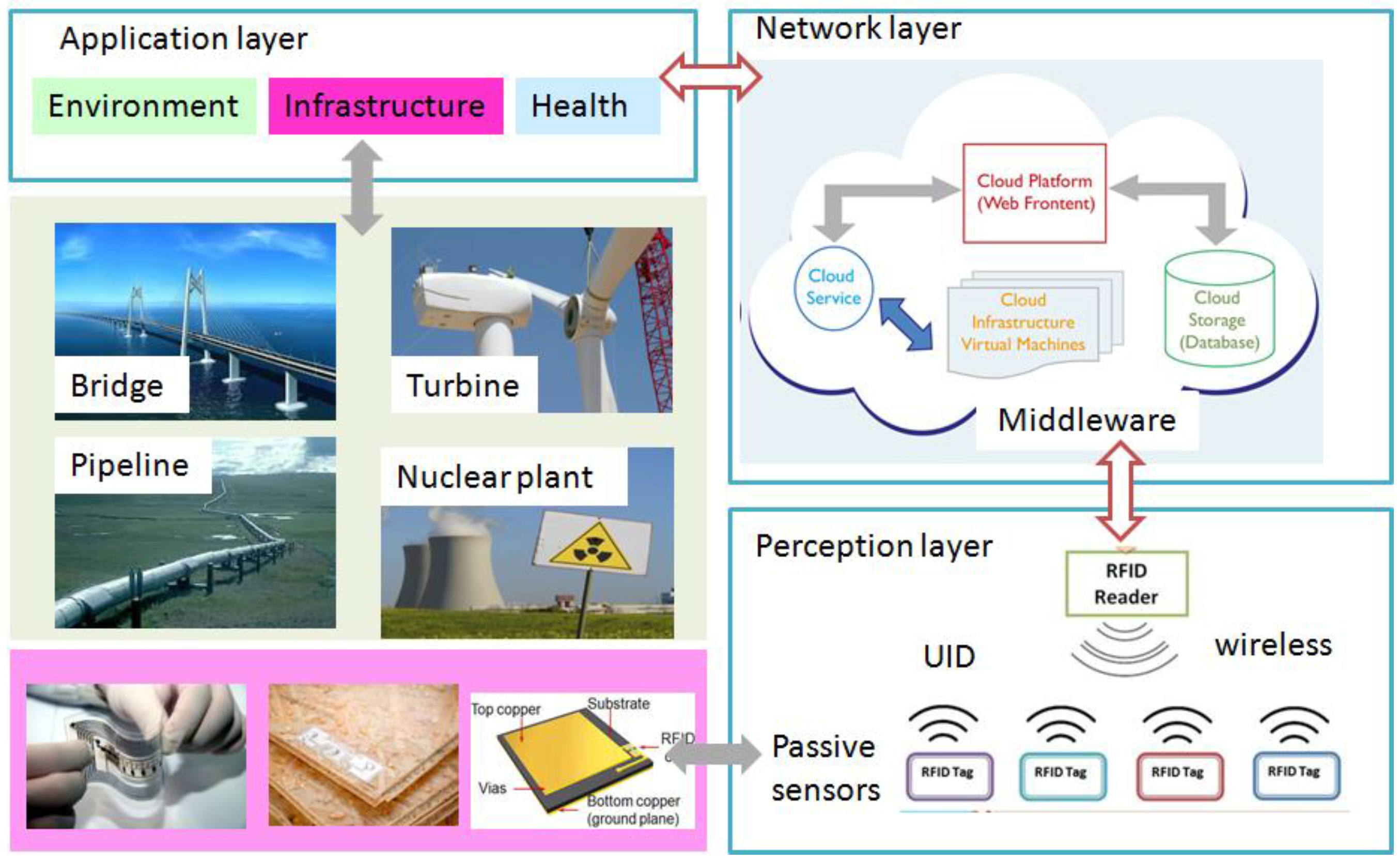
:1. Introduction
- Simple configuration: The antenna itself can serve the dual function of communication and sensing. Therefore, no external sensor is needed. For chipless tags, there is even no electronic device. The sensing information is directly encoded into the antenna backscatter behavior. For this reason, the sensor may function in an extreme environment, e.g., high temperature.
- Passive operation: The tag chip has its own energy harvesting module, as such, no onboard battery is needed.
- Medium read range: The read range for a general passive tag can be up to 10 m, however, the read range largely depends on the frequency, antenna gain, and tag chip’s sensitivity.
- Low cost: The cost for each dipole tag is ~$0.10–0.20 for mass production. The antenna sensors can be fabricated on inexpensive substrate materials, such as paper, PVC, using low-cost fabrication techniques, such as inkjet printing.
- Unique identification: Each tag has its own UID, which is used to identify the location of the defect as well as connect the things into internet. This sensor multiplexing capability enables densely distributed passive WSNs and parallel interrogation of multiple sensors with anti-collision algorithms.
- Multimodality: The antenna can be designed to be sensitive to various physical/mechanical/chemical things in a real-time or periodic.
- Planar or flexible: The antenna sensors can be fabricated on low-profile, flexible substrates that completely conform to the surface they attached to.
- Cover Penetration: The surface of the metal may be covered with paint, cladding, or a similar compound, and the defect may still be detected because microwaves can penetrate dielectric materials.
2. Methodology and Categorization
2.1. Methodology
2.2. Context and Content
3. Communication Issues and Solutions
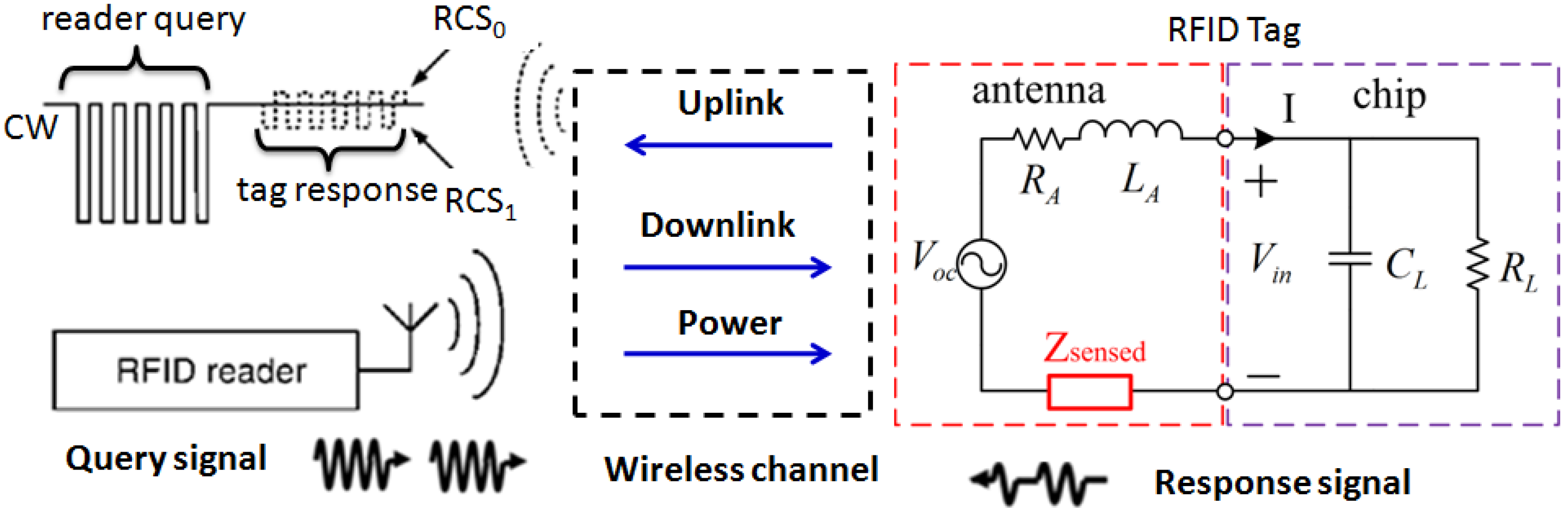
3.1. Backscatter Communication and Measurable Parameters
3.2. Communication-Oriented Issues and Solutions
4. Sensing-Oriented Issues and Solutions
4.1. Defect Types and Antenna Topologies
- Metal mountable: The design of antennas for metal-mountable RFID tags is challenged by a set of limitations: low-profile and conformal structures, to provide good (gain and impedance matching) and reliable operations on conductive platforms of various shapes and sizes.
- Sensing oriented: To be successfully turned into sensors, this class of devices should be able to properly detect and characterize the things (e.g., defects on metallic surface), being, for example monotonic, single-valued, and sensitive enough at least in the most critical ranges. As such, the multi-scale, multi-physics of defect phenomena should be properly modeled before the design of antenna sensor in order to guide the selections of antenna topology and operating mode.
- Balanced performance: RFID communication and sensing capabilities properly demand for opposite requirements: The tag’s antenna is usually designed to be perfectly matched to the tag chip in a reference condition, e.g., at healthy state, and it undergoes mismatching along with the continuous variation (propagation) of measurand. Therefore, a trade-off between sensing and communication is a challenging task to be tackled.
4.1.1. Strain Detection and Characterization
4.1.2. Crack Detection and Characterization
4.1.3. Corrosion Detection and Characterization
4.2. Materials and Manufacturing Technologies
4.3. Sensing Variables and Measurement Uncertainties
4.4. Feature Extraction and Characterization
5. Future Trends and Perspectives
5.1. Integration and Standardization
5.2. More Ubiquitous and Adaptable
5.3. More Simple and Reliable
5.4. UK Highlights
6. Conclusions
Acknowledgments
Author Contributions
Conflicts of Interest
References
- Lynch, J.P.; Farrar, C.R.; Michaels, J.E. Structural health monitoring: Technological advances to practical implementations. Proc. IEEE 2016, 104, 1508–1512. [Google Scholar] [CrossRef]
- Safa, M.; Sabet, A.; Ghahremani, K.; Haas, C.; Walbridge, S. Rail corrosion forensics using 3D imaging and finite element analysis. Int. J. Rail Transp. 2015, 3, 164–178. [Google Scholar] [CrossRef]
- Turnbull, A. Corrosion pitting and environmentally assisted small crack growth. Proc. R. Soc. A 2014, 470, 20140254. [Google Scholar] [CrossRef] [PubMed]
- Hernandez-Valle, F.; Clough, A.R.; Edwards, R.S. Stress corrosion cracking detection using non-contact ultrasonic techniques. Corros. Sci. 2014, 78, 335–342. [Google Scholar] [CrossRef]
- Tian, G.Y.; He, Y.Z.; Adewale, I.; Simm, A. Research on spectral response of pulsed eddy current and NDE applications. Sens. Actuators A-Phys. 2013, 189, 313–320. [Google Scholar] [CrossRef]
- Gao, B.; Woo, W.L.; Tian, G.Y. Electromagnetic thermography nondestructive evaluation: Physics-based modeling and pattern mining. Sci. Rep. 2016, 6, 25480. [Google Scholar] [CrossRef]
- Cook, B.S.; Shamim, A.; Tentzeris, M.M. Passive low-cost inkjet-printed smart skin sensor for structural health monitoring. IET Microw. Antennas Propag. 2012, 6, 1536–1541. [Google Scholar] [CrossRef]
- Cook, B.S.; Vyas, R.; Sangkil, K.; Trang, T.; Taoran, L.; Traille, A.; Aubert, H.; Tentzeris, M.M. RFID-Based Sensors for Zero-Power Autonomous Wireless Sensor Networks. IEEE Sens. J. 2014, 14, 2419–2431. [Google Scholar] [CrossRef]
- Chen, M.; Mao, S.; Liu, Y. Big data: A survey. Mob. Netw. Appl. 2014, 19, 171–209. [Google Scholar] [CrossRef]
- Lee, Y.; Blaauw, D.; Sylvester, D. Ultralow power circuit design for wireless sensor nodes for structural health monitoring. Proc. IEEE 2016, 104, 1529–1546. [Google Scholar] [CrossRef]
- Bhattacharyya, R.; Floerkemeier, C.; Sarma, S. Low-cost, ubiquitous rfid-tag-antenna-based sensing. Proc. IEEE 2010, 98, 1593–1600. [Google Scholar] [CrossRef]
- Tentzeris, M.M.; Georgiadis, A.; Roselli, L. Energy harvesting and scavenging. Proc. IEEE 2014, 102, 1644–1648. [Google Scholar] [CrossRef]
- Occhiuzzi, C.; Caizzone, S.; Marrocco, G. Passive UHF RFID antennas for sensing applications: Principles, methods, and classifcations. IEEE Antennas Propag. Mag. 2013, 55, 14–34. [Google Scholar] [CrossRef]
- Mayer, M.; Goertz, N. RFID tag acquisition via compressed sensing: Fixed vs. random signature assignment. IEEE Trans. Wirel. Commun. 2016, 15, 2118–2129. [Google Scholar] [CrossRef]
- Lodato, R.; Marrocco, G. Close Integration of a UHF-RFID transponder into a limb prosthesis for tracking and sensing. IEEE Sens. J. 2016, 16, 1806–1813. [Google Scholar] [CrossRef]
- Rida, A.; Li, Y.; Tentzeris, M.M. RFID-Enabled Sensor Design and Applications; Artech House: Boston, MA, USA, 2010. [Google Scholar]
- Xu, L.D.; He, W.; Li, S.C. Internet of Things in Industries: A Survey. IEEE Trans. Ind. Inf. 2014, 10, 2233–2243. [Google Scholar] [CrossRef]
- Marrocco, G.; Amato, F. Self-sensing passive RFID: From theory to tag design and experimentation. In Proceedings of the 39th European Microwave Conference (EuMC), Rome, Italy, 29 September–1 October 2009; pp. 1–4.
- Kim, S.; Mariotti, C.; Alimenti, F.; Mezzanotte, P.; Georgiadis, A.; Collado, A.; Roselli, L.; Tentzeris, M.M. No battery required: Perpetual RFID-enabled wireless sensors for cognitive intelligence applications. IEEE Microw. Mag. 2013, 14, 66–77. [Google Scholar] [CrossRef]
- Chen, T.; Tian, G.Y.; Sophian, A.; Que, P.W. Feature extraction and selection for defect classification of pulsed eddy current NDT. NdtE Int. 2008, 41, 467–476. [Google Scholar] [CrossRef]
- Dobmann, G.; Altpeter, I.; Sklarczyk, C.; Pinchuk, R. Non-Destructive Testing with Micro- and MM-Waves—Where we are—Where we go. Weld. World 2012, 56, 111–120. [Google Scholar] [CrossRef]
- Carvalho, N.B.; Georgiadis, A.; Costanzo, A.; Rogier, H.; Collado, A.; Garcia, J.A.; Lucyszyn, S.; Mezzanotte, P.; Kracek, J.; Masotti, D.; et al. Wireless Power Transmission: R&D Activities Within Europe. IEEE Trans. Microw. Theory Tech. 2014, 62, 1031–1045. [Google Scholar]
- Finkenzeller, K. RFID Handbook: Fundamentals and Applications in Contactless Smart Card, Radio Frequency Identification and Near-Field Communication, 3rd ed.; Wiley: Wiltshire, UK, 2010. [Google Scholar]
- Kharkovsky, S.; Zoughi, R. Microwave and millimeter wave nondestructive testing and evaluation—Overview and recent advances. IEEE Instrum. Meas. Mag. 2007, 10, 26–38. [Google Scholar] [CrossRef]
- Zoughi, R.; Kharkovsky, S. Microwave and millimetre wave sensors for crack detection. Fatigue Fract. Eng. Mater. Struct. 2008, 31, 695–713. [Google Scholar] [CrossRef]
- Huang, H.Y. Flexible Wireless Antenna Sensor: A Review. IEEE Sens. J. 2013, 13, 3865–3872. [Google Scholar] [CrossRef]
- Huang, H.Y. Antenna Sensors in Passive Wireless Sensing Systems. In Handbook of Antenna Technologies; Chen, Z.N., Ed.; Springer: Singapore, 2015; pp. 1–34. [Google Scholar]
- Li, S.C.; Xu, L.D.; Zhao, S.S. The internet of things: A survey. Inf. Syst. Front. 2015, 17, 243–259. [Google Scholar] [CrossRef]
- Al-Fuqaha, A.; Guizani, M.; Mohammadi, M.; Aledhari, M.; Ayyash, M. Internet of things: A survey on enabling technologies, protocols, and applications. IEEE Commun. Surv. Tutor. 2015, 17, 2347–2376. [Google Scholar] [CrossRef]
- Mohammad, I.; Huang, H.Y. Monitoring fatigue crack growth and opening using antenna sensors. Smart Mater. Struct. 2010, 19, 055023. [Google Scholar] [CrossRef]
- Mohammad, I.; Huang, H.Y. An antenna sensor for crack detection and monitoring. Adv. Struct. Eng. 2011, 14, 47–53. [Google Scholar] [CrossRef]
- Kalansuriya, P.; Bhattacharyya, R.; Sarma, S.; Karmakar, N. Towards Chipless RFID-Based Sensing for Pervasive Surface Crack Detection. In Proceedings of the IEEE International Conference on RFID-Technologies and Applications (RFID-TA), Nice, France, 5–7 November 2012; pp. 46–51.
- Mohammad, I.; Gowda, V.; Zhai, H.; Huang, H.Y. Detecting crack orientation using patch antenna sensors. Meas. Sci. Technol. 2012, 23, 1–9. [Google Scholar] [CrossRef]
- Xu, X.; Huang, H.Y. Multiplexing passive wireless antenna sensors for multi-site crack detection and monitoring. Smart Mater. Struct. 2012, 21, 015004. [Google Scholar] [CrossRef]
- Kalansuriya, P.; Bhattacharyya, R.; Sarma, S. RFID tag antenna-based sensing for pervasive surface crack detection. IEEE Sens. J. 2013, 13, 1564–1570. [Google Scholar] [CrossRef]
- Yi, X.; Cho, C.; Cooper, J.; Wang, Y.; Tentzeris, M.M.; Leon, R.T. Passive wireless antenna sensor for strain and crack sensing-electromagnetic modeling, simulation, and testing. Smart Mater. Struct. 2013, 22, 085009. [Google Scholar] [CrossRef]
- Caizzone, S.; DiGiampaolo, E.; Marrocco, G. Wireless crack monitoring by stationary phase measurements from Coupled RFID Tags. IEEE Trans. Antennas Propag. 2014, 62, 6412–6419. [Google Scholar] [CrossRef]
- Cho, C.; Yi, X.; Li, D.; Wang, Y.; Tentzeris, M.M. Passive Wireless Frequency Doubling Antenna Sensor for Strain and Crack Sensing. IEEE Sens. J. 2016, 16, 5725–5733. [Google Scholar] [CrossRef]
- Merilampi, S.; Bjorninen, T.; Ukkonen, L.; Ruuskanen, P.; Sydanheimo, L. Embedded wireless strain sensors based on printed RFID tag. Sens. Rev. 2011, 31, 32–40. [Google Scholar] [CrossRef]
- Occhiuzzi, C.; Paggi, C.; Marrocco, G. Passive RFID strain-sensor based on meander-line antennas. IEEE Trans. Antennas Propag. 2011, 59, 4836–4840. [Google Scholar] [CrossRef] [Green Version]
- Daliri, A.; Galehdar, A.; Rowe, W.S.T.; Ghorbani, K.; John, S. Utilising microstrip patch antenna strain sensors for structural health monitoring. J. Intell. Mater. Syst. Struct. 2012, 23, 169–182. [Google Scholar] [CrossRef]
- Kim, J.; Wang, Z.; Kim, W.S. Stretchable RFID for wireless strain sensing with silver nano ink. IEEE Sens. J. 2014, 14, 4395–4401. [Google Scholar] [CrossRef]
- Rakibet, O.O.; Rumens, C.V.; Batchelor, J.C.; Holder, S.J. Epidermal passive RFID strain sensor for assisted technologies. IEEE Antennas Wirel. Propag. Lett. 2014, 13, 814–817. [Google Scholar] [CrossRef]
- Hasani, M.; Vena, A.; Sydanheimo, L.; Tentzeris, M.M.; Ukkonen, L. A Novel Enhanced-Performance Flexible RFID-Enabled Embroidered Wireless Integrated Module for Sensing Applications. IEEE Trans. Compon. Packag. Manuf. Technol. 2015, 5, 1244–1252. [Google Scholar] [CrossRef]
- Zhang, Y.F.; Bai, L.J. Rapid structural condition assessment using radio frequency identification (RFID) based wireless strain sensor. Autom. Constr. 2015, 54, 1–11. [Google Scholar] [CrossRef]
- Yi, X.; Wu, T.; Wang, Y.; Tentzeris, M.M. Sensitivity modeling of an RFID-based strain-sensing antenna with dielectric constant change. IEEE Sens. J. 2015, 15, 6147–6155. [Google Scholar] [CrossRef]
- Alamin, M.; Tian, G.Y.; Andrews, A.; Jackson, P. Corrosion detection using low-frequency RFID technology. Insight 2012, 54, 72–75. [Google Scholar] [CrossRef]
- Khalifeh, R.; Yasri, M.S.; Lescop, B.; Gallee, F.; Diler, E.; Thierry, D.; Rioual, S. Development of wireless and passive corrosion sensors for material degradation monitoring in coastal zones and immersed environment. IEEE J. Ocean. Eng. 2016, 41, 776–782. [Google Scholar] [CrossRef]
- Sunny, A.I.; Tian, G.Y.; Zhang, J.; Pal, M. Low frequency (LF) RFID sensors and selective transient feature extraction for corrosion characterisation. Sens. Actuators A-Phys. 2016, 241, 34–43. [Google Scholar] [CrossRef]
- Zhang, H.; Yang, R.; He, Y.; Tian, G.Y.; Xu, L.; Wu, R. Identification and characterisation of steel corrosion using passive high frequency RFID sensors. Measurement 2016, 92, 421–427. [Google Scholar] [CrossRef]
- Zhang, J.; Tian, G.Y. UHF RFID tag antenna-based sensing for corrosion detection & characterization using principal component analysis. IEEE Trans. Antennas Propag. 2016, 64, 4405–4414. [Google Scholar]
- Huang, H.; Chen, P.-Y.; Hung, C.-H.; Gharpurey, R.; Akinwande, D. A zero power harmonic transponder sensor for ubiquitous wireless μL liquid-volume monitoring. Sci. Rep. 2016, 6, 18795. [Google Scholar] [CrossRef] [PubMed]
- Cazeca, M.J.; Mead, J.; Chen, J.; Nagarajan, R. Passive wireless displacement sensor based on RFID technology. Sens. Actuators A-Phys. 2013, 190, 197–202. [Google Scholar] [CrossRef]
- Paggi, C.; Occhiuzzi, C.; Marrocco, G. Sub-millimeter displacement sensing by passive UHF RFID antennas. IEEE Trans. Antennas Propag. 2014, 62, 905–912. [Google Scholar] [CrossRef] [Green Version]
- Virtanen, J.; Ukkonen, L.; Bjorninen, T.; Elsherbeni, A.Z.; Sydanheimo, L. Inkjet-Printed Humidity Sensor for Passive UHF RFID Systems. IEEE Trans. Instrum. Meas. 2011, 60, 2768–2777. [Google Scholar] [CrossRef]
- Manzari, S.; Occhiuzzi, C.; Nawale, S.; Catini, A.; Di Natale, C.; Marrocco, G. Humidity Sensing by Polymer-Loaded UHF RFID Antennas. IEEE Sens. J. 2012, 12, 2851–2858. [Google Scholar] [CrossRef] [Green Version]
- Gao, J.L.; Siden, J.; Nilsson, H.E.; Gulliksson, M. Printed humidity sensor with memory functionality for passive RFID tags. IEEE Sens. J. 2013, 13, 1824–1834. [Google Scholar] [CrossRef]
- Amin, E.M.; Bhuiyan, M.S.; Karmakar, N.C.; Winther-Jensen, B. Development of a low cost printable Chipless RFID humidity sensor. IEEE Sens. J. 2014, 14, 140–149. [Google Scholar] [CrossRef]
- Occhiuzzi, C.; Rida, A.; Marrocco, G.; Tentzeris, M.M. RFID passive gas sensor integrating carbon nanotubes. IEEE Trans. Microw. Theory Tech. 2011, 59, 2674–2684. [Google Scholar] [CrossRef] [Green Version]
- Potyrailo, R.A.; Surman, C. A passive radio-frequency identification (RFID) gas sensor with self-correction against fluctuations of ambient temperature. Sens. Actuators B-Chem. 2013, 185, 587–593. [Google Scholar] [CrossRef] [PubMed]
- Manzari, S.; Marrocco, G. Modeling and applications of a chemical-loaded UHF RFID sensing antenna with tuning capability. IEEE Trans. Antennas Propag. 2014, 62, 94–101. [Google Scholar] [CrossRef]
- Girbau, D.; Ramos, A.; Lazaro, A.; Rima, S.; Villarino, R. Passive wireless temperature sensor based on time-coded UWB chipless RFID tags. IEEE Trans. Microw. Theory Tech. 2012, 60, 3623–3632. [Google Scholar] [CrossRef]
- Li, F.; Xiang, D.; Chiang, S.; Tittmann, B.R.; Searfass, C. Wireless Surface Acoustic Wave Radio Frequency Identification (SAW-RFID) Sensor System for Temperature and Strain Measurements. In Proceedings of the IEEE International Ultrasonics Symposium (IUS), Dresden, Germany, 7–10 October 2012.
- Saldanha, N.; Malocha, D.C. Pseudo-Orthogonal Frequency Coded Wireless SAW RFID Temperature Sensor Tags. IEEE Trans. Ultrason. Ferroelectr. Freq. Control 2012, 59, 1750–1758. [Google Scholar] [CrossRef] [PubMed]
- Kang, A.L.; Zhang, C.R.; Ji, X.J.; Han, T.; Li, R.S.; Li, X.W. SAW-RFID enabled temperature sensor. Sens. Actuators A-Phys. 2013, 201, 105–113. [Google Scholar] [CrossRef]
- Amendola, S.; Bovesecchi, G.; Palombi, A.; Coppa, P.; Marrocco, G. Design, Calibration and experimentation of an epidermal RFID sensor for remote temperature monitoring. IEEE Sens. J. 2016, 16, 7250–7257. [Google Scholar] [CrossRef]
- Martínez-Martínez, J.J.; Herraiz-Martínez, F.J.; Galindo-Romera, G. Design and Characterization of a Passive Temperature Sensor Based on a Printed MIW Delay Line. IEEE Sens. J. 2016, 16, 7884–7891. [Google Scholar] [CrossRef]
- Noor, T.; Habib, A.; Amin, Y.; Loo, J.; Tenhunen, H. High-density chipless RFID tag for temperature sensing. Electron. Lett. 2016, 52, 620–621. [Google Scholar] [CrossRef]
- Fiddes, L.K.; Yan, N. RFID tags for wireless electrochemical detection of volatile chemicals. Sens. Actuators B 2013, 186, 817–823. [Google Scholar] [CrossRef]
- Amin, E.M.; Saha, J.K.; Karmakar, N.C. Smart sensing materials for low-cost chipless RFID sensor. IEEE Sens. J. 2014, 14, 2198–2207. [Google Scholar] [CrossRef]
- Industrial Research Vision. Available online: https://www.rcnde.ac.uk/ndevr-2/industrial-research-vision/ (accessed on 12 December 2016).
- Huang, Q.A.; Dong, L.; Wang, L.F. LC Passive Wireless Sensors Toward a Wireless Sensing Platform: Status, Prospects, and Challenges. J. Microelectromech. Syst. 2016, 25, 822–841. [Google Scholar] [CrossRef]
- EPC™ Radio-Frequency Identity Protocols Generation-2 UHF RFID: Specification for RFID Air Interface Protocol for Communications at 860 MHz – 960 MHz (Version 2.0.1 Ratified); GS1: Lawrenceville, NJ, USA, 2015.
- Roy, S.; Jandhyala, V.; Smith, J.R.; Wetherall, D.J.; Otis, B.P.; Chakraborty, R.; Buettner, M.; Yeager, D.J.; Ko, Y.C.; Sample, A.P. RFID: From Supply Chains to Sensor Nets. Proc. IEEE 2010, 98, 1583–1592. [Google Scholar] [CrossRef]
- Boyer, C.; Roy, S. Space Time Coding for Backscatter RFID. IEEE Trans. Wirel. Commun. 2013, 12, 2272–2280. [Google Scholar] [CrossRef]
- Zhang, J.; Tian, G.Y.; Zhao, A.B. Passive RFID sensor systems for crack detection & characterization. NdtE Int. 2017, 86, 89–99. [Google Scholar]
- IEEE Standard for Air Interface for Broadband Wireless Access Systems; IEEE: Berkeley, CA, USA, 2012; pp. 1–2542.
- Kimionis, J.; Bletsas, A.; Sahalos, J.N. Increased Range Bistatic Scatter Radio. IEEE Trans. Commun. 2014, 62, 1091–1104. [Google Scholar] [CrossRef]
- Mukhopadhyay, B.; Sarangi, S.; Kar, S. Novel RSSI evaluation models for accurate indoor localization with sensor networks. In Proceedings of the 20th National Conference on Communications (NCC), Kanpur, India, 28 February–2 March 2014; pp. 1–6.
- Nikitin, P.V.; Martinez, R.; Ramamurthy, S.; Leland, H.; Spiess, G.; Rao, K.V.S. Phase based spatial identification of UHF RFID tags. In Proceedings of the IEEE International Conference on RFID, Orlando, FL, USA, 14–15 April 2010; pp. 102–109.
- Chakraborty, R.; Roy, S.; Jandhyala, V. Revisiting RFID link budgets for technology scaling: Range maximization of RFID tags. IEEE Trans. Microw. Theory Tech. 2011, 59, 496–503. [Google Scholar] [CrossRef]
- Boyer, C.; Roy, S. Backscatter Communication and RFID: Coding, Energy, and MIMO Analysis. IEEE Trans. Commun. 2014, 62, 770–785. [Google Scholar] [CrossRef]
- Whitney, A.; Fessler, J.; Parker, J.; Jacobs, N. Received signal strength indication signature for passive UHF tags. In Proceedings of the IEEE/ASME International Conference on Advanced Intelligent Mechatronics, Besancon, France, 8–11 July 2014; pp. 1183–1187.
- Griffin, J.D.; Durgin, G.D. Complete Link Budgets for Backscatter-Radio and RFID Systems. IEEE Antennas Propag. Mag. 2009, 51, 11–25. [Google Scholar] [CrossRef]
- Dimitriou, A.G.; Bletsas, A.; Sahalos, J.N. Room-Coverage Improvements in UHF RFID with Commodity Hardware. IEEE Antennas Propag. Mag. 2011, 53, 175–194. [Google Scholar] [CrossRef]
- Bekkali, A.; Zou, S.; Kadri, A.; Crisp, M.; Penty, R. Performance analysis of passive UHF RFID systems under cascaded fading channels and interference effects. IEEE Trans. Wirel. Commun. 2014, 14, 1421–1433. [Google Scholar] [CrossRef]
- Biguesh, M.; Gazor, S.; Shariat, M.H. Optimal training sequence for MIMO wireless systems in colored environments. IEEE Trans. Signal Process. 2009, 57, 3144–3153. [Google Scholar] [CrossRef]
- Griffin, J.D.; Durgin, G.D. Gains For RF Tags Using Multiple Antennas. IEEE Trans. Antennas Propag. 2008, 56, 563–570. [Google Scholar] [CrossRef]
- Grey, S.; von Bögel, G.; Hennig, A.; Grabmaier, A. Pseudorandom Noise based Channel Coding Scheme for Tag to Reader Communication in UHF-RFID Systems. In Proceedings of the European Conference on Smart Objects, Systems and Technologies (SmartSysTech), Munich, Germany, 12–13 June 2012; pp. 1–4.
- Capdevila, S.; Jofre, L.; Romeu, J.; Bolomey, J.C. Multi-loaded modulated scatterer technique for sensing applications. IEEE Trans. Instrum. Meas. 2013, 62, 794–805. [Google Scholar] [CrossRef]
- Durgin, G.D.; Valenta, C.R.; Akbar, M.B.; Morys, M.M.; Marshall, B.R.; Lu, Y. Modulation and Sensitivity Limits for Backscatter Receivers. In Proceedings of the IEEE International Conference on RFID, Orlando, FL, USA, 30 April–2 May 2013; pp. 124–130.
- Sievenpiper, D.; Zhang, L.J.; Broas, R.F.J.; Alexopolous, N.G.; Yablonovitch, E. High-impedance electromagnetic surfaces with a forbidden frequency band. IEEE Trans. Microw. Theory Tech. 1999, 47, 2059–2074. [Google Scholar] [CrossRef]
- Hazdra, P.; Capek, M.; Eichler, J.; Mazanek, M. The Radiation Q-Factor of a Horizontal lambda/2 Dipole Above Ground Plane. IEEE Antennas Wirel. Propag. Lett. 2014, 13, 1073–1075. [Google Scholar] [CrossRef]
- Balanis, C.A. Antenna Theory: Analysis and Design, 3rd ed.; John Wiley & Sons: New Jersey, NJ, USA, 2005. [Google Scholar]
- Boybay, M.S.; Ramahi, O.M. Near-field probes using double and single negative media. Phys. Rev. E 2009, 79, 016602. [Google Scholar] [CrossRef] [PubMed]
- Hu, B.; Ren, Z.; Boybay, M.S.; Ramahi, O.M. Waveguide probe loaded with split-ring resonators for crack detection in metallic surfaces. IEEE Trans. Microw. Theory Tech. 2014, 62, 871–878. [Google Scholar] [CrossRef]
- Zhang, J.; Long, Y.L. A novel metal-mountable electrically small antenna for RFID tag applications with practical guidelines for the antenna design. IEEE Trans. Antennas Propag. 2014, 11, 5820–5829. [Google Scholar] [CrossRef]
- Bjorninen, T.; Sydanheimo, L.; Ukkonen, L.; Rahmat-Samii, Y. Advances in antenna designs for UHF RFID tags mountable on conductive items. IEEE Antennas Propag. Mag. 2014, 56, 79–103. [Google Scholar] [CrossRef]
- Occhiuzzi, C.; Marrocco, G. Constrained-design of passive UHF RFID sensor antennas. IEEE Trans. Antennas Propag. 2013, 61, 2972–2980. [Google Scholar] [CrossRef] [Green Version]
- Caizzone, S.; DiGiampaolo, E. Wireless passive RFID crack width sensor for structural health monitoring. IEEE Sens. J. 2015, 15, 6767–6774. [Google Scholar] [CrossRef]
- Wen, G.Y. Physical limitations of antenna. IEEE Trans. Antennas Propag. 2003, 51, 2116–2123. [Google Scholar]
- Yaghjian, A.D.; Best, R.S. Impedance, bandwidth, and Q of antennas. IEEE Trans. Antennas Propag. 2005, 53, 1298–1324. [Google Scholar] [CrossRef]
- Gustafsson, M.; Cismasu, M.; Jonsson, B.L.G. Physical bounds and optimal currents on antennas. IEEE Trans. Antennas Propag. 2012, 60, 2672–2681. [Google Scholar] [CrossRef]
- Junker, G.P.; Kishk, A.A.; Glisson, A.W.; Kajifez, D. Effect of air gap on cylindrical dielectric resonator antenna operating in TM01 mode. Electronics Lett. 1994, 30, 97–98. [Google Scholar] [CrossRef]
- Garg, R.; Bhartia, P.; Bahl, I.; Ittipiboon, A. Microstrip Antenna Design Handbook; Artech House: Norwood, MA, USA, 2001. [Google Scholar]
- Bae, S.-H.; Lee, Y.; Sharma, B.K.; Lee, H.-J.; Kim, J.-H.; Ahn, J.-H. Graphene-based transparent strain sensor. Carbon 2013, 51, 236–242. [Google Scholar] [CrossRef]
- Hasani, M.; Vena, A.; Sydanheimo, L.; Ukkonen, L.; Tentzeris, M.M. Implementation of a Dual-Interrogation-Mode Embroidered RFID-Enabled Strain Sensor. IEEE Antennas Wirel. Propag. Lett. 2013, 12, 1272–1275. [Google Scholar] [CrossRef]
- Yagi, K.; Sato, N.; Sato, Y.; Tamakawa, K.; Minkov, D.; Shoji, T. Detection and evaluation of the depth of surface cracks in conductive materials by using a loop antenna. Appl. Phys. A Mater. Sci. Process. 2003, 77, 461–468. [Google Scholar] [CrossRef]
- Gotoh, Y.; Hirano, H.; Nakano, M.; Fujiwara, K.; Takahashi, N. Electromagnetic nondestructive testing of rust region in steel. IEEE Trans. Magn. 2005, 41, 3616–3618. [Google Scholar] [CrossRef]
- Gustafsson, M.; Jonsson, B.L.G. Antenna Q and stored energy expressed in the fields, currents, and input impedance. IEEE Trans. Antennas Propag. 2015, 63, 240–249. [Google Scholar] [CrossRef]
- Khan, S.; Tinku, S.; Lorenzelli, L.; Dahiya, R.S. Flexible tactile sensors using screen-printed P(VDF-TrFE) and MWCNT/PDMS composites. IEEE Sens. J. 2015, 15, 3146–3155. [Google Scholar] [CrossRef]
- Ru, C.; Luo, J.; Xie, S.; Sun, Y. A review of non-contact micro- and nano-printing technologies. J. Micromech. Microeng. 2014, 24, 5. [Google Scholar] [CrossRef]
- Pietrikova, A.; Lukacs, P.; Jakubeczyova, D.; Ballokova, B.; Potencki, J.; Tomaszewski, G.; Pekarek, J.; Prikrylova, K.; Fides, M. Surface analysis of polymeric substrates used for inkjet printing technology. Circuit World 2016, 42, 9–16. [Google Scholar] [CrossRef]
- Cummins, G.; Desmulliez, M.P.Y. Inkjet printing of conductive materials: A review. Circuit World 2012, 38, 193–213. [Google Scholar] [CrossRef]
- Khan, S.; Lorenzelli, L.; Dahiya, R.S. Technologies for Printing Sensors and Electronics Over Large Flexible Substrates: A Review. IEEE Sens. J. 2015, 15, 3164–3185. [Google Scholar] [CrossRef]
- Potyrailo, R.A.; Burns, A.; Surman, C.; Lee, D.J.; McGinniss, E. Multivariable passive RFID vapor sensors: Roll-to-roll fabrication on a flexible substrate. Analyst 2012, 137, 2777–2781. [Google Scholar] [CrossRef] [PubMed]
- Dang, M.C.; Dang, T.M.D.; Eric, F.-B. Silver nanoparticles ink synthesis for conductive patterns fabrication using inkjet printing technology. Adv. Nat. Sci.-Nanosci. Nanotechnol. 2015, 6, 1. [Google Scholar] [CrossRef]
- Scoutaris, N.; Ross, S.; Douroumis, D. Current Trends on Medical and Pharmaceutical Applications of Inkjet Printing Technology. Pharm. Res. 2016, 33, 1799–1816. [Google Scholar] [CrossRef] [PubMed]
- Rim, Y.S.; Bae, S.H.; Chen, H.J.; De Marco, N.; Yang, Y. Recent progress in materials and devices toward printable and flexible sensors. Adv. Mater. 2016, 28, 4415–4440. [Google Scholar] [CrossRef] [PubMed]
- Rida, A.; Yang, L.; Vyas, R.; Tentzeris, M.M. Conductive inkjet-printed antennas on flexible low-cost paper-based substrates for RFID and WSN applications. IEEE Antennas Propag. Mag. 2009, 51, 13–23. [Google Scholar] [CrossRef]
- Lakafosis, V.; Rida, A.; Vyas, R.; Li, Y.; Nikolaou, S.; Tentzeris, M.M. Progress towards the first wireless sensor networks consisting of inkjet-printed, paper-based RFID-enabled sensor tags. Proc. IEEE 2010, 98, 1601–1609. [Google Scholar] [CrossRef]
- Janeczek, K.; Jakubowska, M.; Koziol, G.; Mlozniak, A. Electrical and mechanical properties of RFID chip joints assembled on flexible substrates. Solder. Surf. Mount Technol. 2015, 27, 13–21. [Google Scholar] [CrossRef]
- Kamyshny, A.; Magdassi, S. Conductive nanomaterials for printed electronics. Small 2014, 10, 3515–3535. [Google Scholar] [CrossRef] [PubMed]
- Leng, T.; Huang, X.J.; Chang, K.H.; Chen, J.C.; Abdalla, M.A.; Hu, Z.R. Graphene nanoflakes printed flexible meandered-line dipole antenna on paper substrate for low-cost RFID and sensing applications. IEEE Antennas Wirel. Propag. Lett. 2016, 15, 1565–1568. [Google Scholar] [CrossRef]
- Tung, T.T.; Yock, J.; Alotaibi, F.K.; Nine, M.J.; Karunagaran, R.; Krebsz, M.; Nguyen, G.T.; Tran, D.N.H.; Feller, J.F.; Losic, D. Graphene oxide-assisted liquid phase exfoliation of graphite into graphene for highly conductive film and electromechanical sensors. ACS Appl. Mater. Interfaces 2016, 8, 16521–16532. [Google Scholar] [CrossRef] [PubMed]
- Akbari, M.; Khan, M.W.A.; Hasani, M.; Bjorninen, T.; Sydanheimo, L.; Ukkonen, L. Fabrication and characterization of graphene antenna for low-cost and environmentally friendly RFID tags. IEEE Antennas Wirel. Propag. Lett. 2015, 15, 1569–1572. [Google Scholar] [CrossRef]
- Li, Y.; Rida, A.; Vyas, R.; Tentzeris, M.M. RFID Tag and RF structures on a paper substrate using inkjet-printing technology. IEEE Trans. Microw. Theory Tech. 2007, 55, 2894–2901. [Google Scholar]
- Leenen, M.A.M.; Arning, V.; Thiem, H.; Steiger, J.; Anselmann, R. Printable electronics: Flexibility for the future. Phys. Status Solidi A-Appl. Mater. Sci. 2009, 206, 588–597. [Google Scholar] [CrossRef]
- Preradovic, S.; Roy, S.M.; Karmakar, N.C. RFID system based on fully printable chipless tag for paper-/plastic-ltem tagging. IEEE Antennas Propag. Mag. 2011, 53, 15–32. [Google Scholar] [CrossRef]
- Bessonov, A.A.; Kirikova, M.N. Flexible and printable sensors. Nanotechnol. Russia 2015, 10, 165–180. [Google Scholar] [CrossRef]
- Cui, Z.; Ma, C.; Chen, Z.; Su, W.; Zhao, J.; Lin, J.; Qui, S. Printed Electronics: Materials, Technologies and Applications; John Wiley & Sons: Hoboken, NJ, USA, 2016. [Google Scholar]
- Talla, V.; Smith, J.R. Hybrid analog-digital backscatter: A new approach for battery-free sensing. In Proceedings of the IEEE International Conference on RFID, Orlando, FL, USA, 30 April–2 May 2013; pp. 74–81.
- Occhiuzzi, C.; Marrocco, G. Precision and accuracy in UHF-RFID power measurements for passive sensing. IEEE Sens. J. 2016, 16, 3091–3098. [Google Scholar] [CrossRef]
- Li, Y.; Tian, G.Y.; Simm, A. Fast analytical modelling for pulsed eddy current evaluation. NdtE Int. 2008, 41, 477–483. [Google Scholar] [CrossRef]
- Fasarakis-Hilliard, N.; Alevizos, P.N.; Bletsas, A. Coherent detection and channel coding for bistatic scatter radio sensor networking. IEEE Trans. Commun. 2015, 63, 1798–1810. [Google Scholar] [CrossRef]
- Occhiuzzi, C.; Marrocco, G. Uncertainty and applicability of rfid power measurements for passive sensing. In Proceedings of the 44th European Microwave Conference (EuMC), Rome, Italy, 6–9 October 2014; pp. 255–258.
- Caizzone, S.; DiGiampaolo, E.; Marrocco, G. Constrained pole-zero synthesis of phase-oriented RFID sensor antennas. IEEE Trans. Antennas Propag. 2016, 64, 496–503. [Google Scholar] [CrossRef]
- Kuester, D.; Popovic, Z. How good is your tag?: RFID backscatter metrics and measurements. IEEE Microw. Mag. 2013, 14, 47–55. [Google Scholar] [CrossRef]
- Pouzin, A.; Vuong, T.-P.; Tedjini, S.; Pouyet, M.; Perdereau, J.; Dreux, L. Determination of measurement uncertainties applied to the RCS and the differential RCS of UHF passive RFID tags. In Proceedings of the IEEE Antennas and Propagation Society International Symposium, Charleston, SC, USA, 1–5 June 2009; pp. 1–4.
- Kuester, D.G.; Novotny, D.R.; Guerrieri, J.R.; Ibrahim, A.; Popovic, Z.B. Simple Test and Modeling of RFID Tag Backscatter. IEEE Trans. Microw. Theory Tech. 2012, 60, 2248–2258. [Google Scholar] [CrossRef]
- Bowler, J.R.; Norton, S.J.; Harrison, D.J. Eddy-current interaction with an ideal crack. II. The inverse problem. J. Appl. Phys. 1994, 75, 8138–8144. [Google Scholar] [CrossRef]
- Firoozy, N.; Tavakoli, A. Buried crack reconstruction through far-field electromagnetic inverse scattering measurement. NdtE Int. 2013, 54, 84–90. [Google Scholar] [CrossRef]
- Yu, J. Local and global principal component analysis for process monitoring. J. Process Control 2012, 22, 1358–1373. [Google Scholar] [CrossRef]
- Bhattacharyya, R. Low-Cost, Passive UHF RFID Tag Antenna-Based Sensors for Pervasive Sensing Applications. Ph.D Thesis, Massachusetts Institute of Technology, Cambridge, MA, USA, 2012. [Google Scholar]
- Li, H.; Tan, Y.; Lau, B.K.; Ying, Z.N.; He, S.L. Characteristic mode based tradeoff analysis of antenna-chassis interactions for multiple antenna terminals. IEEE Trans. Antennas Propag. 2012, 60, 490–502. [Google Scholar] [CrossRef]
- Yee, A.; Garbacz, R.J. Self- and mutual-admittances of wire antennas in terms of characteristic modes. IEEE Trans. Antennas Propag. 1973, 21, 868–871. [Google Scholar] [CrossRef]
- Adams, J.J.; Bernhard, J.T. Broadband Equivalent Circuit Models for Antenna Impedances and Fields Using Characteristic Modes. IEEE Trans. Antennas Propag. 2013, 61, 3985–3994. [Google Scholar] [CrossRef]
- Hughes, D.; Zoughi, R. A novel method for determination of dielectric properties of materials using a combined embedded modulated scattering and near-field microwave techniques-Part I: Forward model. IEEE Trans. Instrum. Meas. 2005, 54, 2389–2397. [Google Scholar]
- Marrocco, G.; Caizzone, S. Electromagnetic models for passive tag-to-tag communications. IEEE Trans. Antennas Propag. 2012, 60, 5381–5389. [Google Scholar] [CrossRef] [Green Version]
- Caizzone, S.; Marrocco, G. RFID Grids: Part II-Experimentations. IEEE Trans. Antennas Propag. 2011, 59, 2896–2904. [Google Scholar] [CrossRef]
- Marrocco, G. RFID Grids: Part I-Electromagnetic Theory. IEEE Trans. Antennas Propag. 2011, 59, 1019–1026. [Google Scholar] [CrossRef]
- Caizzone, S.; Marrocco, G. RFID-Grids for deformation sensing. In Proceedings of the IEEE Antennas and Propagation Society International Symposium, Chicago, IL, USA, 8–14 July 2012.
- Zou, Z.; Mendoza, D.S.; Wang, P.; Zhou, Q.; Mao, J.; Jonsson, F.; Tenhunen, H.; Zheng, L.R. A Low-Power and Flexible Energy Detection IR-UWB Receiver for RFID and Wireless Sensor Networks. IEEE Trans. Circuits Syst. I-Regul. Pap. 2011, 58, 1470–1482. [Google Scholar] [CrossRef]
- Dardari, D.; D’Errico, R.; Roblin, C.; Sibille, A.; Win, M.Z. Ultrawide Bandwidth RFID: The Next Generation? Proc. IEEE 2010, 98, 1570–1582. [Google Scholar] [CrossRef]
- Liu, H.; Bolic, M.; Nayak, A.; Stojmenovic, I. Taxonomy and challenges of the integration of RFID and wireless sensor networks. IEEE Netw. 2008, 22, 26–32. [Google Scholar] [CrossRef]
- Chin, K.-W.; Klair, D. E(2)MAC: An energy efficient MAC for RFID-enhanced wireless sensor networks. Pervasive Mob. Comput. 2011, 7, 241–255. [Google Scholar] [CrossRef]
- De Donno, D.; Catarinucci, L.; Tarricone, L. A battery-assisted sensor-enhanced RFID tag enabling heterogeneous wireless sensor networks. IEEE Sens. J. 2014, 14, 1048–1055. [Google Scholar] [CrossRef]
- Wang, L.; Xu, L.D.; Bi, Z.; Xu, Y. Data cleaning for RFID and WSN integration. IEEE Trans. Ind. Inf. 2014, 10, 408–418. [Google Scholar] [CrossRef]
- Vizziello, A.; Savazzi, P. Efficient RFID tag identification exploiting hybrid UHF-UWB tags and compressive sensing. IEEE Sens. J. 2016, 16, 4932–4939. [Google Scholar] [CrossRef]
- Gubbi, J.; Buyya, R.; Marusic, S.; Palaniswami, M. Internet of Things (IoT): A vision, architectural elements, and future directions. Futur. Gener. Comput. Syst. 2013, 29, 1645–1660. [Google Scholar] [CrossRef]
- He, S.; Chen, J.; Jiang, F.; Yau, D.K.Y.; Xing, G.; Sun, Y. Energy provisioning in wireless rechargeable sensor networks. IEEE Trans. Mob. Comput. 2013, 12, 1931–1942. [Google Scholar] [CrossRef]
- Catarinucci, L.; Colella, R.; Tarricone, L. Enhanced UHF RFID sensor-tag. IEEE Microw. Wirel. Compon. Lett. 2013, 23, 49–51. [Google Scholar] [CrossRef]
- Smith, J.R. Wirelessly Powered Sensor Networks and Computational RFID; Springer: New York, NY, USA, 2013. [Google Scholar]
- Catarinucci, L.; Colella, R.; Esposito, A.; Tarricone, L.; Zappatore, M. RFID sensor-tags feeding a context-aware rule-based healthcare monitoring system. J. Med. Syst. 2012, 36, 3435–3449. [Google Scholar] [CrossRef] [PubMed]
- Al-Turjman, F.M.; Al-Fagih, A.E.; Alsalih, W.M.; Hassanein, H.S. A delay-tolerant framework for integrated RSNs in IoT. Comput. Commun. 2013, 36, 998–1010. [Google Scholar] [CrossRef]
- Lopez, T.S. RFID and sensor integration standards: State and future prospects. Comput. Stand. Interfaces 2011, 33, 207–213. [Google Scholar] [CrossRef]
- Farris, I.; Militano, L.; Iera, A.; Molinaro, A.; Spinella, S.C. Tag-based cooperative data gathering and energy recharging in wide area RFID sensor networks. Ad Hoc Netw. 2016, 36, 214–228. [Google Scholar] [CrossRef]
- Gozalvez, J. New 3GPP Standard for IoT [Mobile Radio]. IEEE Veh. Technol. Mag. 2016, 11, 14–20. [Google Scholar] [CrossRef]
- ETSI TS 136 300 V13.4.0 (2016-08): Overall Description; Stage 2 (Release 13); ETSI: Valbonne, France, 2016; pp. 1–321.
- Oh, S.M.; Shin, J. An efficient small data transmission scheme in the 3GPP NB-IoT system. IEEE Commun. Lett. 2016, PP, 1. [Google Scholar] [CrossRef]
- Law, M.K.; Bermak, A.; Luong, H.C. A Sub-mu W embedded CMOS temperature sensor for RFID food monitoring application. IEEE J. Solid-State Circuits 2010, 45, 1246–1255. [Google Scholar] [CrossRef]
- Yin, J.; Yi, J.; Law, M.K.; Ling, Y.X.; Lee, M.C.; Ng, K.P.; Gao, B.; Luong, H.C.; Bermak, A.; Chan, M.; et al. A system-on-chip EPC Gen-2 passive UHF RFID tag with embedded temperature sensor. IEEE J. Solid-State Circuits 2010, 45, 2404–2420. [Google Scholar]
- Reinisch, H.; Wiessflecker, M.; Gruber, S.; Unterassinger, H.; Hofer, G.; Klamminger, M.; Pribyl, W.; Holweg, G. A multifrequency passive sensing tag with on-chip temperature sensor and off-chip sensor interface using EPC HF and UHF RFID technology. IEEE J. Solid-State Circuits 2011, 46, 3075–3088. [Google Scholar] [CrossRef]
- Wegleiter, H.; Schweighofer, B.; Deinhammer, C.; Holler, G.; Fulmek, P. Automatic Antenna Tuning Unit to Improve RFID System Performance. IEEE Trans. Instrum. Meas. 2011, 60, 2797–2803. [Google Scholar] [CrossRef]
- Magnus® S3 Sensor IC. Available online: http://rfmicron.com/magnus-s3/ (accessed on 12 December 2016).
- Caccami, M.C.; Marrocco, G. Electromagnetic characterisation of self-tuning UHF RFID tags for sensing application. In Proceedings of the IEEE International Symposium on Antennas and Propagation (APSURSI), Fajardo, Puerto Rico, 26 June–1 July 2016; pp. 1273–1274.
- Saini, N.S.; Burkholder, R.J.; Volakis, J.L. Smart sensing and data logging using RFID. In Proceedings of the IEEE International Symposium on Antennas and Propagation (APSURSI), Fajardo, Puerto Rico, 26 June–1 July 2016; pp. 1277–1278.
- Caizzone, S.; Occhiuzzi, C.; Marrocco, G. Multi-chip RFID antenna integrating shape-memory alloys for detection of thermal thresholds. IEEE Trans. Antennas Propag. 2011, 59, 2488–2494. [Google Scholar] [CrossRef] [Green Version]
- Sauer, S.; Fischer, W.J. An irreversible single-use humidity-threshold monitoring sensor principle for wireless passive sensor solutions. IEEE Sens. J. 2016, 16, 6920–6930. [Google Scholar] [CrossRef]
- Liao, Y.Z.; Leeson, M.S.; Higgins, M.D. A communication link analysis based on biological implant wireless body area networks. Appl. Comput. Electromagn. Soc. J. 2016, 31, 619–628. [Google Scholar]
- Barman, J.; Uswatte, G.; Ghaffari, T.; Sokal, B.; Byrom, E.; Trinh, E.; Brewer, M.; Varghese, C.; Sarkar, N. Sensor-enabled RFID system for monitoring arm activity: Reliability and validity. IEEE Trans. Neural Syst. Rehabil. Eng. 2012, 20, 771–777. [Google Scholar] [CrossRef] [PubMed]
- Yilmaz, T.; Foster, R.; Hao, Y. Detecting vital signs with wearable wireless sensors. Sensors 2010, 10, 10837–10862. [Google Scholar] [CrossRef] [PubMed] [Green Version]
- Akbari, M.; Virkki, J.; Sydänheimo, L.; Ukkonen, L. Toward graphene-based passive UHF RFID textile tags: A reliability study. IEEE Trans. Device Mater. Reliab. 2016, 16, 429–431. [Google Scholar] [CrossRef]
- Li, Y.; Martin, L.J.; Staiculescu, D.; Wong, C.P.; Tentzeris, M.M. Conformal magnetic composite RFID for wearable RF and bio-monitoring applications. IEEE Trans. Microw. Theory Tech. 2008, 56, 3223–3230. [Google Scholar]
- Kellomaki, T. On-body performance of a wearable single-layer RFID tag. IEEE Antennas Wirel. Propag. Lett. 2012, 11, 73–76. [Google Scholar] [CrossRef]
- Koski, K.; Sydanheimo, L.; Rahmat-Samii, Y.; Ukkonen, L. Fundamental characteristics of electro-textiles in wearable UHF RFID patch antennas for body-centric sensing systems. IEEE Trans. Antennas Propag. 2014, 62, 6454–6462. [Google Scholar] [CrossRef]
- Occhiuzzi, C.; Cippitelli, S.; Marrocco, G. Modeling, Design and Experimentation of Wearable RFID Sensor Tag. IEEE Trans. Antennas Propag. 2010, 58, 2490–2498. [Google Scholar] [CrossRef] [Green Version]
- Manzari, S.; Occhiuzzi, C.; Marrocco, G. Feasibility of body-centric systems using passive textile RFID tags. IEEE Antennas Propag. Mag. 2012, 54, 49–62. [Google Scholar] [CrossRef] [Green Version]
- Besnoff, J.S.; Deyle, T.; Harrison, R.R.; Reynolds, M.S. Battery-free multichannel digital ECG biotelemetry using UHF RFID techniques. In Proceedings of the IEEE International Conference on RFID, Orlando, FL, USA, 30 April–2 May 2013; pp. 16–22.
- De Donno, D.; Ricciato, F.; Tarricone, L. Listening to tags: Uplink RFID measurements with an open-source software-defined radio tool. IEEE Trans. Instrum. Meas. 2013, 62, 109–118. [Google Scholar] [CrossRef]
- Catarinucci, L.; De Donno, D.; Colella, R.; Ricciato, F.; Tarricone, L. A Cost-Effective SDR Platform for Performance Characterization of RFID Tags. IEEE Trans. Instrum. Meas. 2012, 61, 903–911. [Google Scholar] [CrossRef]
- Harma, S.; Arthur, W.G.; Hartmann, C.S.; Maev, R.G.; Plessky, V.P. Inline SAW RFID tag using time position and phase encoding. IEEE Trans. Ultrasonics Ferroelectr. Freq. Control 2008, 55, 1840–1846. [Google Scholar] [CrossRef] [PubMed]
- Javed, N.; Habib, A.; Amin, Y.; Loo, J.; Akram, A.; Tenhunen, H. Directly printable moisture sensor tag for intelligent packaging. IEEE Sens. J. 2016, 16, 6147–6148. [Google Scholar] [CrossRef]
- Wang, L.B.; Li, L.L.; Li, Y.B.; Zhang, H.C.; Cui, T.J. Single-shot and single-sensor high/super-resolution microwave imaging based on metasurface. Sci. Rep. 2016, 6, 26959. [Google Scholar] [CrossRef] [PubMed]
- Vena, A.; Sydanheimo, L.; Tentzeris, M.M.; Ukkonen, L. A fully inkjet-printed wireless and chipless sensor for co2 and temperature detection. IEEE Sens. J. 2015, 15, 89–99. [Google Scholar] [CrossRef]
- Vena, A.; Perret, E.; Tedjini, S. High-capacity chipless RFID tag insensitive to the polarization. IEEE Trans. Antennas Propag. 2012, 60, 4509–4515. [Google Scholar] [CrossRef]
- Polivka, M.; Havlicek, J.; Svanda, M.; Machac, J. Improvement in Robustness and Recognizability of RCS Response of U Shaped Strip-Based Chipless RFID Tags. IEEE Antennas Wirel. Propag. Lett. 2016, 15, 2000–2003. [Google Scholar] [CrossRef]
- Lee, J.S.; Oh, J.; Jun, J.; Jang, J. Wireless hydrogen smart sensor based on pt/graphene-immobilized radio-frequency identification tag. ACS Nano 2015, 9, 7783–7790. [Google Scholar] [CrossRef] [PubMed]
- Cheng, H.T.; Ren, X.H.; Ebadi, S.; Chen, Y.H.; An, L.N.; Gong, X. Wireless passive temperature sensors using integrated cylindrical resonator/antenna for harsh-environment applications. IEEE Sens. J. 2015, 15, 1453–1462. [Google Scholar] [CrossRef]
- Boccard, J.M.; Aftab, T.; Hoppe, J.; Yousaf, A.; Hutter, R.; Reindl, L.M. High-resolution, far-field, and passive temperature sensing up to 700 degrees C using an Isolated ZST microwave dielectric resonator. IEEE Sens. J. 2016, 16, 715–722. [Google Scholar] [CrossRef]
- Powell, A.W.; Coles, D.M.; Taylor, R.A.; Watt, A.A.R.; Assender, H.E.; Smith, J.M. Plasmonic Gas Sensing Using Nanocube Patch Antennas. Adv. Opt. Mater. 2016, 4, 634–642. [Google Scholar] [CrossRef]
- Hodge, V.J.; O’Keefe, S.; Weeks, M.; Moulds, A. Wireless sensor networks for condition monitoring in the railway industry: A survey. IEEE Trans. Intell. Transp. Syst. 2015, 16, 1088–1106. [Google Scholar] [CrossRef]
- Matthews, J.; Irvine, N.; McInnes, D. Through-life engineering for nuclear plant. In Proceedings of the 2nd International through-Life Engineering Services Conference, Cranfield, UK, 5–6 November 2013.
- Panitz, M.; Hope, D.C.; Sato, T.; Harley, C.D.; Christopoulos, C.; Sewell, P.; Dawson, J.F.; Marvin, A.C.; Fearon, E.; Watkins, K.G.; et al. The opportunities and challenges associated with wireless interconnects in aircraft. Proc. Inst. Mech. Eng. Part G-J. Aerosp. Eng. 2010, 224, 459–470. [Google Scholar] [CrossRef]
- Jarvis, R.; Cawley, P.; Nagy, P.B. Current deflection NDE for the inspection and monitoring of pipes. NdtE Int. 2016, 81, 46–59. [Google Scholar] [CrossRef]
- Oon, C.S.; Ateeq, M.; Shaw, A.; Al-Shamma’a, A.; Kazi, S.N.; Badarudin, A. Experimental study on a feasibility of using electromagnetic wave cylindrical cavity sensor to monitor the percentage of water fraction in a two phase system. Sens. Actuators A-Phys. 2016, 245, 140–149. [Google Scholar] [CrossRef]
- Meng, Z.; Li, Z. RFID tag as a sensor—A review on the innovative designs and applications. Meas. Sci. Rev. 2016, 16, 305. [Google Scholar] [CrossRef]
- Li, Z.; Meng, Z.Z. A review of the radio frequency non-destructive testing for carbon-fibre composites. Meas. Sci. Rev. 2016, 16, 68–76. [Google Scholar] [CrossRef]
- Jessop, D.S.; Kindness, S.J.; Xiao, L.; Braeuninger-Weimer, P.; Lin, H.; Ren, Y.; Ren, C.X.; Hofmann, S.; Zeitler, J.A.; Beere, H.E.; et al. Graphene based plasmonic terahertz amplitude modulator operating above 100 MHz. Appl. Phys. Lett. 2016, 108. [Google Scholar] [CrossRef] [Green Version]
- Huang, X.J.; Leng, T.; Zhang, X.; Chen, J.C.; Chang, K.H.; Geim, A.K.; Novoselov, K.S.; Hu, Z.R. Binder-free highly conductive graphene laminate for low cost printed radio frequency applications. Appl. Phys. Lett. 2015, 106. [Google Scholar] [CrossRef]
- He, C.R.; Kiziroglou, M.E.; Yates, D.C.; Yeatman, E.M. A MEMS self-powered sensor and RF transmission platform for WSN nodes. IEEE Sens. J. 2011, 11, 3437–3445. [Google Scholar] [CrossRef]
- Lui, K.W.; Murphy, O.H.; Toumazou, C. A wearable wideband circularly polarized textile antenna for effective power transmission on a wirelessly-powered sensor platform. IEEE Trans. Antennas Propag. 2013, 61, 3873–3876. [Google Scholar] [CrossRef]
- Kilinc, E.G.; Baj-Rossi, C.; Ghoreishizadeh, S.; Riario, S.; Stradolini, F.; Boero, C.; De Micheli, G.; Maloberti, F.; Carrara, S.; Dehollain, C. A system for wireless power transfer and data communication of long-term bio-monitoring. IEEE Sens. J. 2015, 15, 6559–6569. [Google Scholar] [CrossRef]
- Pellegrini, A.; Brizzi, A.; Zhang, L.; Ali, K.; Hao, Y.; Wu, X.; Constantinou, C.C.; Nechayev, Y.; Hall, P.S.; Chahat, N. Antennas and propagation for body-centric wireless communications at millimeter-wave frequencies: A review [wireless corner]. IEEE Antennas Propag. Mag. 2013, 55, 262–287. [Google Scholar] [CrossRef]
- Bharadwaj, R.; Parini, C.; Alomainy, A. Experimental Investigation of 3-D Human Body Localization Using Wearable Ultra-Wideband Antennas. IEEE Trans. Antennas Propag. 2015, 63, 5035–5044. [Google Scholar] [CrossRef]
- Munoz, M.O.; Foster, R.; Hao, Y. On-Body Channel Measurement Using Wireless Sensors. IEEE Trans. Antennas Propag. 2012, 60, 3397–3406. [Google Scholar] [CrossRef] [Green Version]
- Nevat, I.; Peters, G.W.; Collings, I.B. Distributed detection in sensor networks over fading channels with multiple antennas at the fusion centre. IEEE Trans. Signal Process. 2014, 62, 671–683. [Google Scholar] [CrossRef]
- Li, S.C.; Tryfonas, T.; Li, H.L. The Internet of Things: A security point of view. Internet Res. 2016, 26, 337–359. [Google Scholar] [CrossRef]
- Lukic, M.; Clarke, J.; Tuck, C.; Whittow, W.; Wells, G. Printability of elastomer latex for additive manufacturing or 3D printing. J. Appl. Polym. Sci. 2016, 133. [Google Scholar] [CrossRef] [Green Version]
- Rumens, C.V.; Ziai, M.A.; Belsey, K.E.; Batchelor, J.C.; Holder, S.J. Swelling of PDMS networks in solvent vapours; applications for passive RFID wireless sensors. J. Mater. Chem. C 2015, 3, 10091–10098. [Google Scholar] [CrossRef]
- Lopez, T.S.; Ranasinghe, D.C.; Harrison, M.; McFarlane, D. Adding sense to the internet of things an architecture framework for smart objective systems. Pers. Ubiquitous Comput. 2012, 16, 291–308. [Google Scholar] [CrossRef]
- Abbasi, Q.H.; Sani, A.; Alomainy, A.; Hao, Y. Numerical characterization and modeling of subject-specific ultrawideband body-centric radio channels and systems for healthcare applications. IEEE Trans. Inf. Technol. Biomed. 2012, 16, 221–227. [Google Scholar] [CrossRef] [PubMed]
- Ali, K.; Brizzi, A.; Lee, S.L.; Yang, G.Z.; Alomainy, A.; Hao, Y. Quantitative analysis of the subject-specific on-body propagation channel based on statistically created models. IEEE Antennas Wirel. Propag. Lett. 2015, 14, 398–401. [Google Scholar] [CrossRef]
- Abbasi, Q.H.; Ur-Rehman, M.; Qaraqe, K.; Alomainy, A. Advances in Body-Centric Wireless Communication: Applications and State-of-the-Art; IET: London, UK, 2016. [Google Scholar]
- Li, X.G.; Zhang, D.W.; Liu, Z.Y.; Li, Z.; Du, C.W.; Dong, C.F. Share corrosion data. Nature 2015, 527, 441–442. [Google Scholar] [CrossRef] [PubMed]


| Journal Titles | Count | % of 442 |
|---|---|---|
| IEEE Sensors Journal | 53 | 11.99 |
| Sensors | 24 | 5.43 |
| IEEE Transactions on Antennas and Propagation | 23 | 5.20 |
| Sensors and Actuators B-Chemical | 16 | 3.62 |
| IEEE Transactions on Microwave Theory and Techniques | 14 | 3.17 |
| IEEE Journal of Solid-State Circuits | 12 | 2.71 |
| Sensors and Actuators A-Physical | 9 | 2.04 |
| IEEE Transactions on Instrumentation and Measurement | 9 | 2.04 |
| (b) | ||
| Countries/Territories | Count | % of 442 | Organization-UK | Count |
|---|---|---|---|---|
| USA | 178 | 40.27 | University of Cambridge | 7 |
| P. R. China | 71 | 16.06 | Imperial College London | 6 |
| Italy | 57 | 12.90 | Newcastle University | 5 |
| Spain | 52 | 11.76 | University of Manchester | 4 |
| Germany | 38 | 8.60 | University of Bristol | 4 |
| South Korea | 27 | 6.11 | University of Kent | 3 |
| France | 27 | 6.11 | Middlesex University | 2 |
| Japan | 22 | 4.98 | Queen Mary University of London | 2 |
| (c) | ||||


| Sensing Principle (Antenna Type) | Sensing Variable | Feature | Pros. | Cons. | Refs. |
|---|---|---|---|---|---|
| Conductor loss resistance (stretchable dipole on fabric substrate) | Backscattered power at turn on threshold | Power variation | Strain level up to 50%;Sensitivity can be modified by conductive material; Read range: 1.5 m | Power is susceptible to wireless channel | [39] |
| Deformation of shape factor (meander line dipole) | Backscattered power | Power variation | Sensitivity: 16%; Read range: 0.6 m | Strain level up to 6% (poor-elastic conductor leads to small yield point) | [40] |
| Coupling (slotted circular patch) | Reflection coefficient (S11) | RFS | Omni-directional strain sensing | VNA is required; Not compatible with Gen2 regulation | [41] |
| Electrical length (fabric-based embroidered dipole) | Dual-interrogation-mode (read range/RCS) | RFS | Strain level up to 16%;Sensitivity: 0.66 parts per million (ppm)/με | Read range: 20 cm; Need calibration; Dedicated receiver | [107] |
| Elastic deformation (patch) | Turn on power | RFS | Read range: 2.1 m; Can be mounted on metallic surface | Sensitivity: 0.7907 ppm/με | [36] |
| LC resonator (PDMS substrate stamped with sliver nano ink) | Reflection coefficient (S11) | RFS | Strain level up to 7%; Chipless; Good mechanical | Sensitivity: 0.51 ppm/με; Read range: 20 cm; VNA is required; Dedicated receiver | [42] |
| Deformation of slot width (dipole on PDMS substrate with stretchable conducting Lycra fabric containing silver threads) | Turn on power | Power variation | Sensitivity: strains of up to 10% causing transmit power differences of about 4 dB; Read range: 1.6 m; Good repeatability | Power is susceptible to wireless channel | [43] |
| Elastic deformation (folded patch) | Turn on power | RFS | Can be mounted on metallic surface | Sensitivity: −0.7404 ppm/με; Read range: 30 cm | [46] |
| Elastic deformation (dual patches) | RCS | RFS | Sensitivity: −5.232 kHz/με | Not compatible with Gen2 regulation Dedicated receiver | [38] |
| Measurand | Sensing Principle (Antenna Type) | Sensing Variable | Feature | Pros. | Cons. | Refs. |
|---|---|---|---|---|---|---|
| Crack depth | Inductive (coil) | Potential drop | Voltage ratio | Resolution: 0.5 mm in depth | Location dependent; VNA is required | [108] |
| Crack (length) growth and orientation detection | 2D grid (meander line dipole) | Reflectometry | Time difference of arrival | Chipless; Large dynamic range | VNA is required | [32] |
| Crack (length) growth and orientation detection | Mode orthogonality (dual-resonant patch) | S11 | RFS | Resolution: sub-mm; Large dynamic range | VNA is required; not compatible with Gen2 regulation | [33] |
| Crack (length) growth and orientation detection | Spatial division (dual-resonant patch) | Backscattered power | Power variation | Multi-site crack | Dedicated receiver | [34] |
| Crack (length) growth and orientation detection | 2D Grid (dipole) | Backscattered power | Power variation | Read range: 1 m | Power is susceptible to wireless channel | [35] |
| Fatigue crack | Deformation (patch) | Turn on power | RFS | Read range: 2.1 m | Large antenna size | [36] |
| Crack (width) growth | Mutual coupling (patch antenna array) | Backscattered phase | Phase shift | Sub-mm resolution; Platform tolerance | Crack position should be known prior; | [37,100] |
| Sensing Principle (Antenna Type) | Sensing Variable | Feature | Pros | Cons | Refs. |
|---|---|---|---|---|---|
| Inductive coupling (coil) | Envelope | Peak value | Fast | Read range: 3 cm; Lift-off dependent | [47,49] |
| Inductive coupling (coil) | Complex impedance | principal component analysis (PCA) | Lift-off independent | Read range: 2.5 cm; VNA is required | [50] |
| Capacitive coupling (3D antenna) | Analogue identifier (AID) | PCA | Read range: 1 m; Wireless channel independent | Antenna profile: 1.6 cm | [51] |
| Stub resonator (patch antenna) | Transmission coefficient (S21) | RFS | Chipless; Read range: 2 m | Influence from immersed water; Not compatible with Gen2 regulation; VNA is required | [48] |
| Areas and Focus | Universities |
|---|---|
| Materials and graphene | University of Cambridge [209] University of Manchester [210] |
| Wireless power transmission | Imperial College Condon [211,212,213] |
| Antennas | Queen Mary University London [214,215] |
| Channel and communication | Queen Mary University London [216,217] |
| Security and privacy | University of Bristol [218] |
| Sensors and systems | Newcastle University [49,50,51] |
| Manufacturing | Loughborough University [219] University of Kent [220] |
| Smart objects applications | Auto-ID Labs at University of Cambridge [221] |
| WBAN for e-health monitoring applications | Queen Mary University London [222,223,224] |
© 2017 by the authors. Licensee MDPI, Basel, Switzerland. This article is an open access article distributed under the terms and conditions of the Creative Commons Attribution (CC BY) license ( http://creativecommons.org/licenses/by/4.0/).
Share and Cite
Zhang, J.; Tian, G.Y.; Marindra, A.M.J.; Sunny, A.I.; Zhao, A.B. A Review of Passive RFID Tag Antenna-Based Sensors and Systems for Structural Health Monitoring Applications. Sensors 2017, 17, 265. https://doi.org/10.3390/s17020265
Zhang J, Tian GY, Marindra AMJ, Sunny AI, Zhao AB. A Review of Passive RFID Tag Antenna-Based Sensors and Systems for Structural Health Monitoring Applications. Sensors. 2017; 17(2):265. https://doi.org/10.3390/s17020265
Chicago/Turabian StyleZhang, Jun, Gui Yun Tian, Adi M. J. Marindra, Ali Imam Sunny, and Ao Bo Zhao. 2017. "A Review of Passive RFID Tag Antenna-Based Sensors and Systems for Structural Health Monitoring Applications" Sensors 17, no. 2: 265. https://doi.org/10.3390/s17020265