High-Sensitivity and Low-Hysteresis Porous MIMType Capacitive Humidity Sensor Using Functional Polymer Mixed with TiO2 Microparticles


Abstract
:1. Introduction
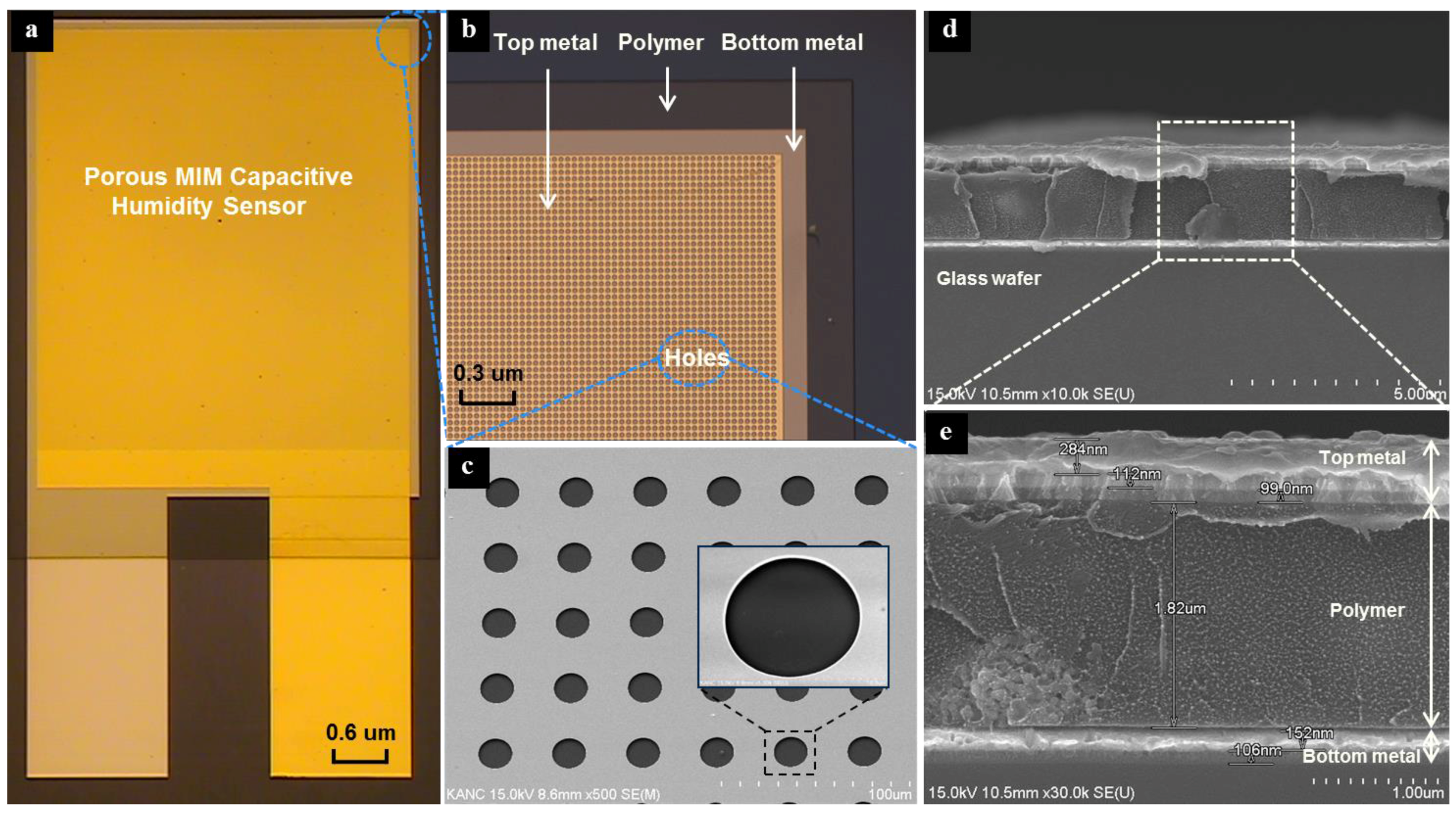
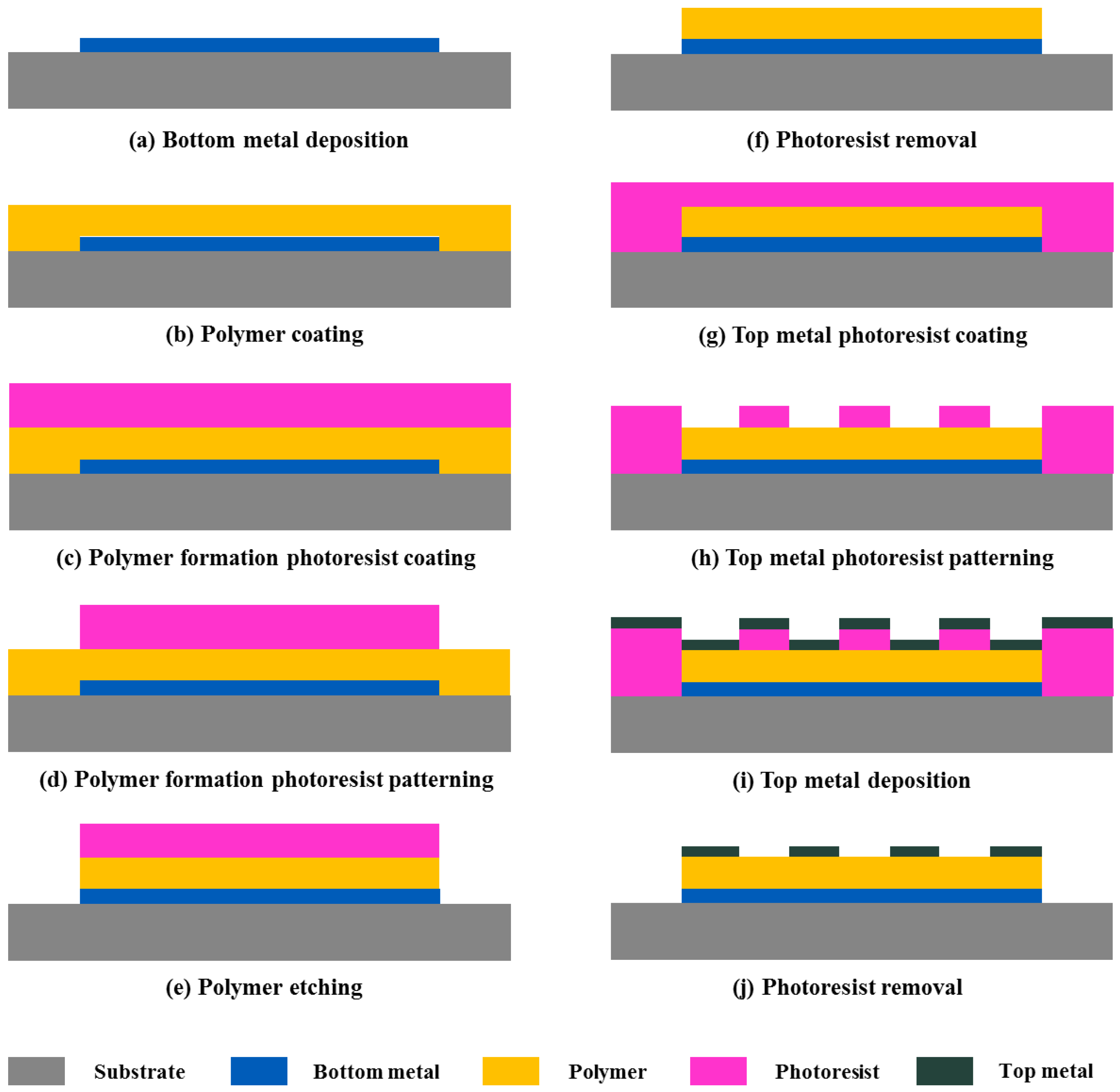
2. Structure and Fabrication
3. Results and Discussion
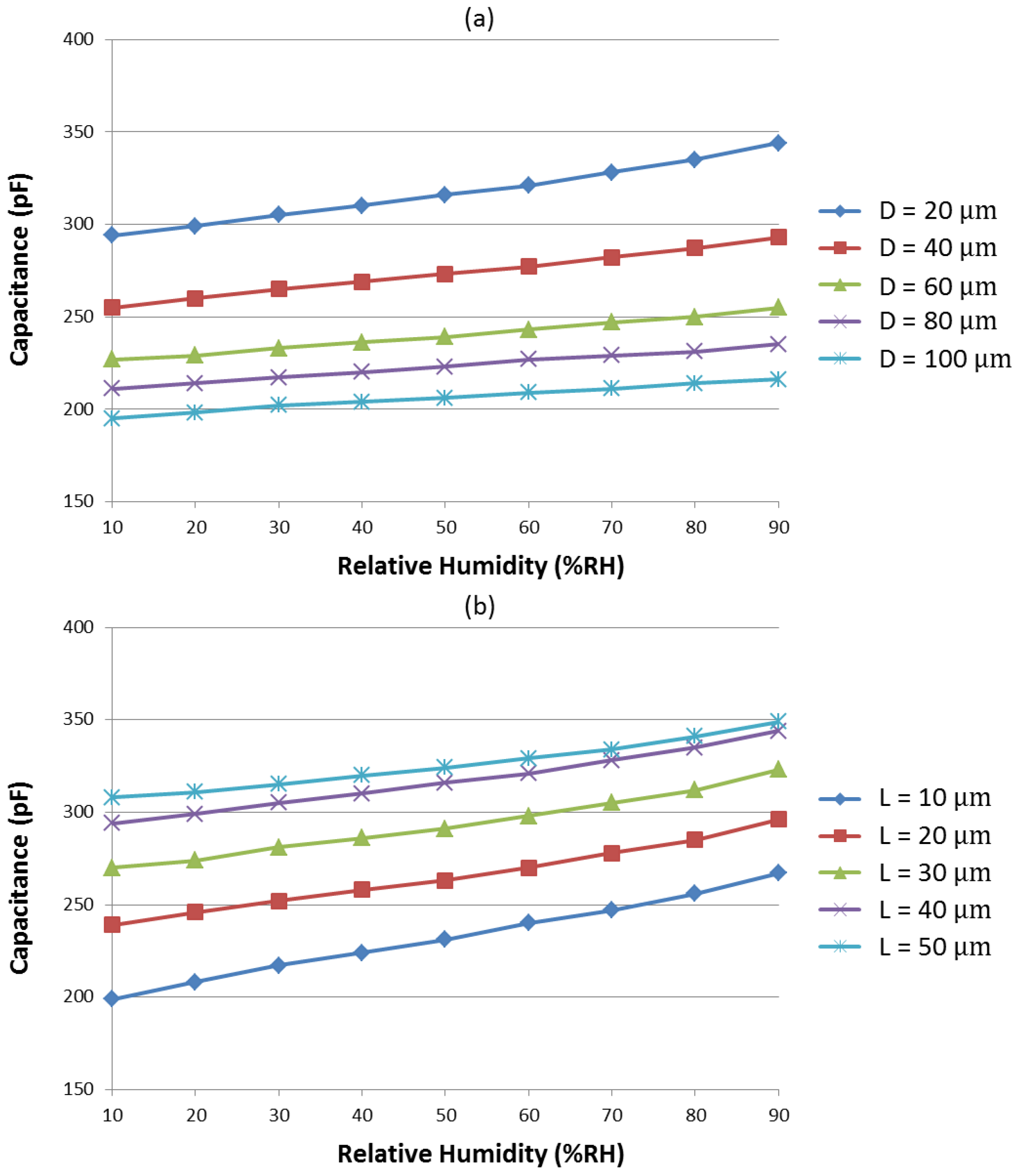
3.1. Sensitivity
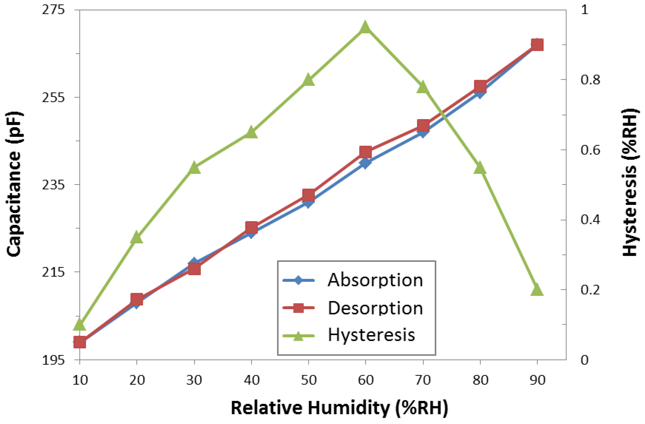
3.2. Hysteresis
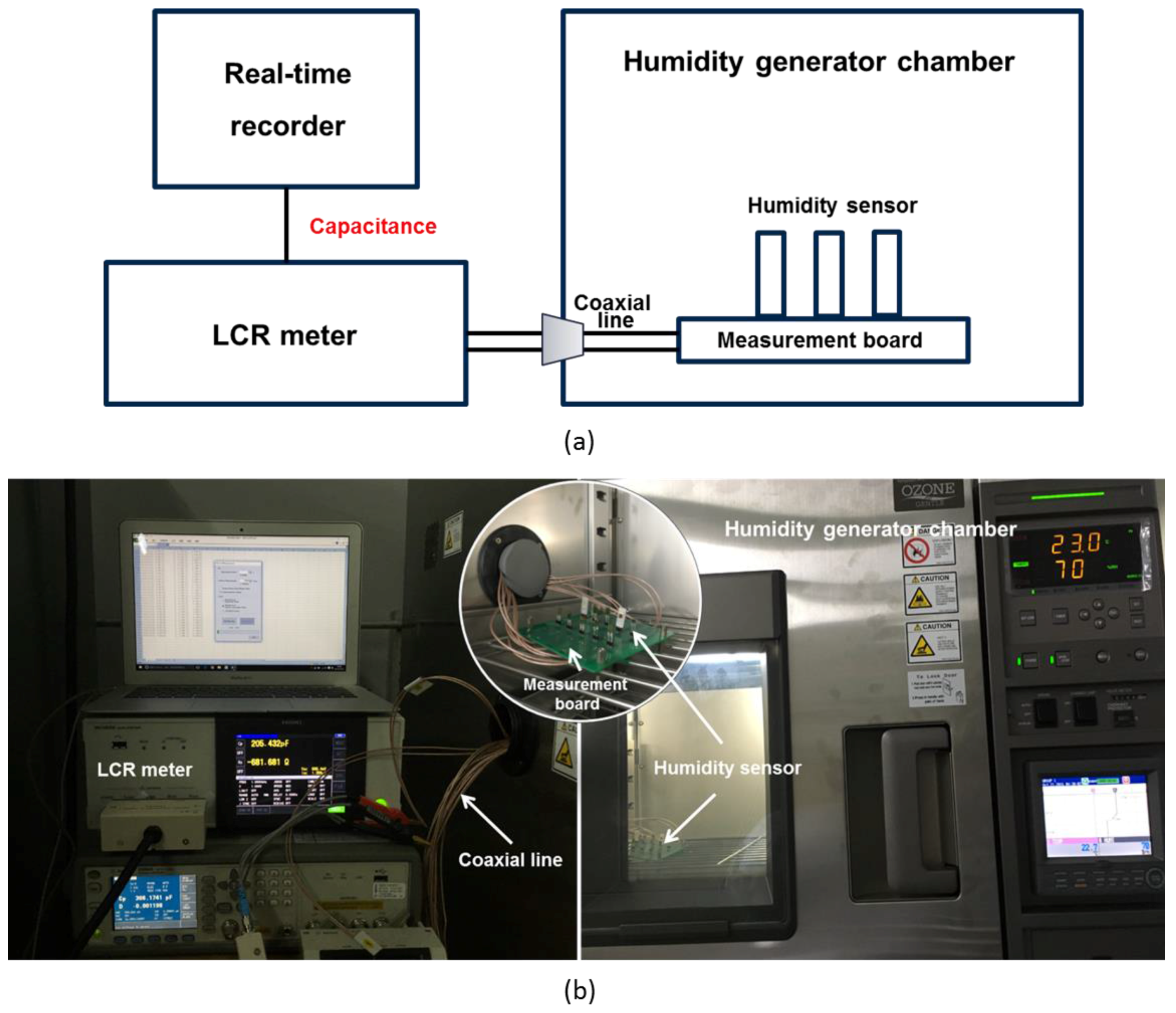
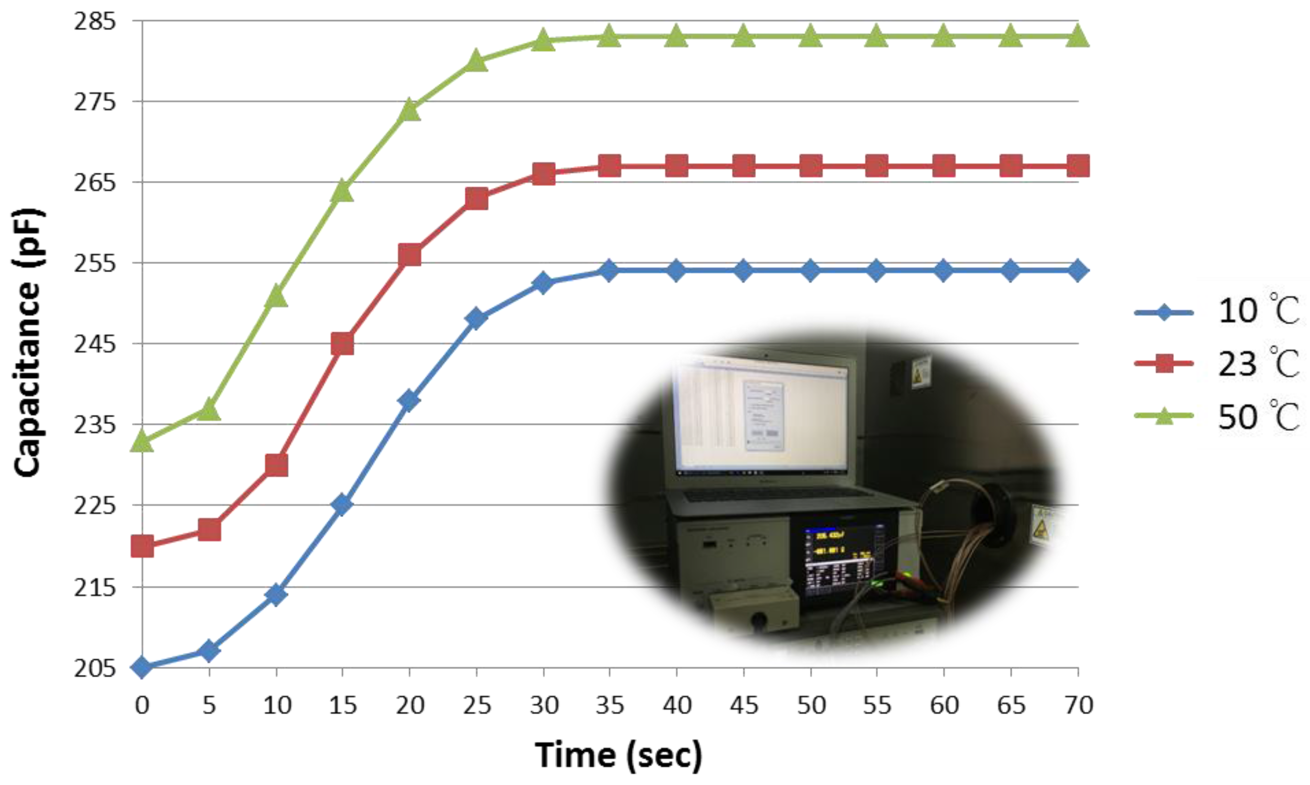
3.3. Response Time
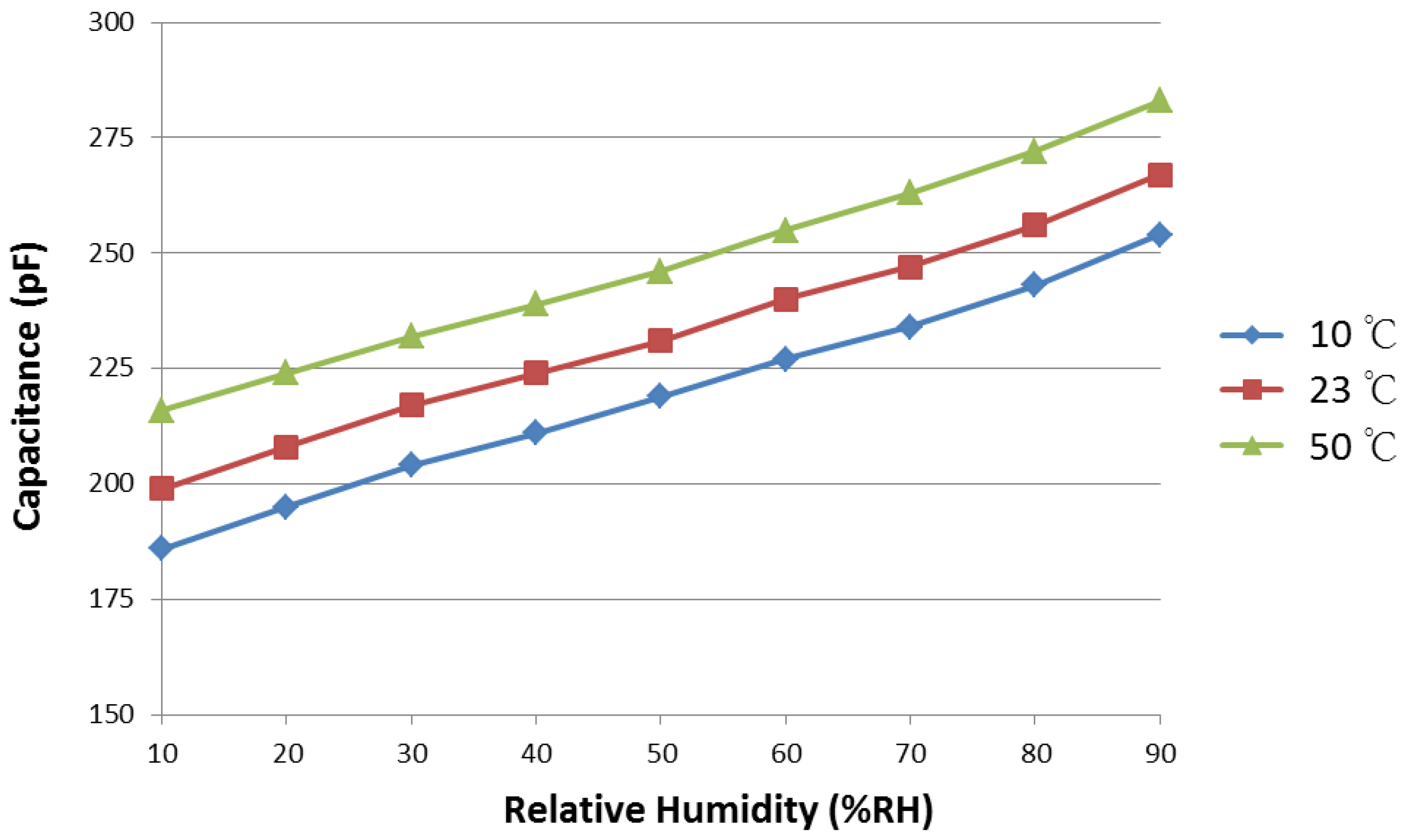
3.4. Temperature Dependence
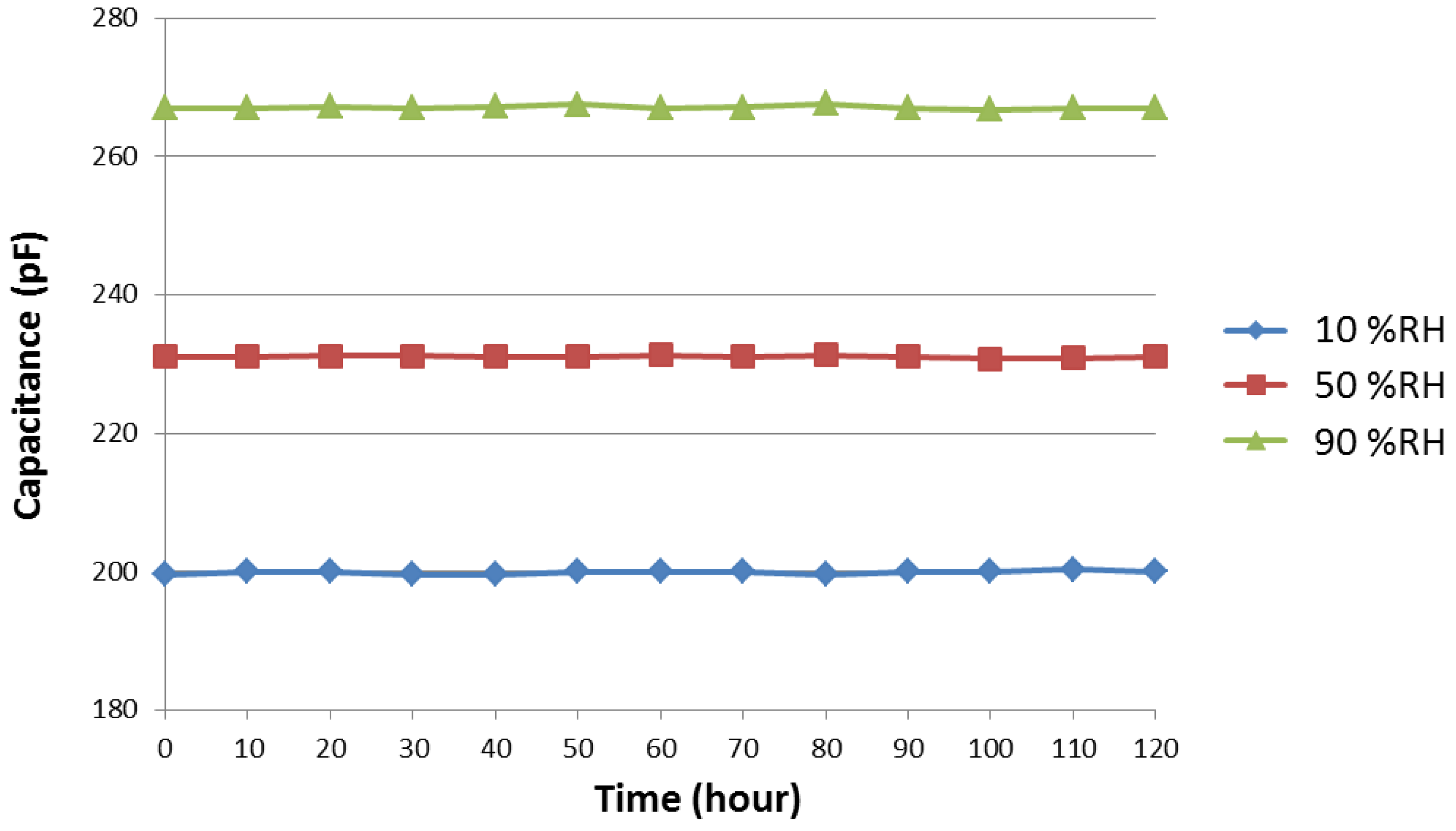
3.5. Stability
4. Conclusions
Acknowledgments
Author Contributions
Conflicts of Interest
References
- Chen, Z.; Lu, C. Humidity sensors: a review of materials and mechanisms. Sensor Lett. 2005, 3, 274–295. [Google Scholar] [CrossRef]
- Lee, C.W.; Lee, S.J.; Kim, M.; Kyung, Y.; Eom, K. Capacitive humidity sensor tag smart refrigerator system using the capacitive to voltage converter. Int. J. Adv. Sci. Technol. 2011, 36, 15–25. [Google Scholar]
- Farahani, H.; Wagiran, R.; Hamidon, M.N. Humidity sensors principle, mechanism, and fabrication technologies: a comprehensive review. Sensors 2014, 14, 7881–7939. [Google Scholar] [CrossRef] [PubMed]
- Feng, Y.; Xie, L.; Chen, Q.; Zheng, L.R. Low-cost printed chipless RFID humidity sensor tag for intelligent packaging. IEEE Sens. J. 2015, 15, 3201–3208. [Google Scholar] [CrossRef]
- Penza, M.; Anisimkin, V.I. Surface acoustic wave humidity sensor using polyvinyl-alcohol film. Sens. Actuator A Phys. 1999, 76, 162–166. [Google Scholar] [CrossRef]
- Xu, L.; Fanguy, J.C.; Soni, K.; Tao, S. Optical fiber humidity sensor based on evanescent-wave scattering. Opt. Lett. 2004, 29, 1191–1193. [Google Scholar] [CrossRef] [PubMed]
- Consales, M.; Buosciolo, A.; Cutolo, A.; Breglio, G.; Irace, A.; Buontempo, S.; Petagna, P.; Giordano, M.; Cusano, A. Fiber optic humidity sensors for high-energy physics applications at CERN. Sens. Actuator B Chem. 2011, 159, 66–74. [Google Scholar] [CrossRef]
- Kolpakov, S.A.; Gordon, N.T.; Mou, C.; Zhou, K. Toward a new generation of photonic humidity sensors. Sensors 2014, 14, 3986–4013. [Google Scholar] [CrossRef] [PubMed]
- Matsuguchi, M.; Umeda, S.; Sadaoka, Y.; Sakai, Y. Characterization of polymers for a capacitive-type humidity sensor based on water sorption behavior. Sens. Actuator B Chem. 1998, 49, 179–185. [Google Scholar] [CrossRef]
- Tetelin, A.; Pellet, C.; Laville, C.; N’Kaoua, G. Fast response humidity sensors for a medical microsystem. Sens. Actuator B Chem. 2003, 91, 211–218. [Google Scholar] [CrossRef]
- Gu, L.; Huang, Q.A.; Qin, M. A novel capacitive-type humidity sensor using CMOS fabrication technology. Sens. Actuator B Chem. 2004, 99, 491–498. [Google Scholar] [CrossRef]
- Wagner, T.; Krotzky, S.; Weiß, A.; Sauerwald, T.; Kohl, C.D.; Roggenbuck, J.; Tiemann, M. A high temperature capacitive humidity sensor based on mesoporous silica. Sensors 2011, 11, 3135–3144. [Google Scholar] [CrossRef] [PubMed]
- Nagata, K.; Nishino, M.; Goto, K.S. Humidity Sensor with SrCe0.95Yb0.05O3 solid electrolyte for high temperature use. J. Electrochem. Soc. 1987, 134, 1850–1854. [Google Scholar] [CrossRef]
- Yang, M.R.; Chen, K.S. Humidity sensors using polyvinyl alcohol mixed with electrolytes. Sens. Actuator B Chem. 1998, 49, 240–247. [Google Scholar] [CrossRef]
- Wang, J.; Xu, B.; Liu, G.; Zhang, J.; Zhang, T. Improvement of nanocrystalline BaTiO3 humidity sensing properties. Sens. Actuator B Chem. 2000, 66, 159–160. [Google Scholar] [CrossRef]
- Li, G.Q.; Lai, P.T.; Huang, M.Q.; Zeng, S.H.; Li, B.; Cheng, Y.C. A humidity-sensing model for metal–insulator–semiconductor capacitors with porous ceramic film. J. Appl. Phys. 2000, 87, 8716–8720. [Google Scholar] [CrossRef]
- Kuang, Q.; Lao, C.; Wang, Z.L.; Xie, Z.; Zheng, L. High-sensitivity humidity sensor based on a single SnO2 nanowire. J. Am. Chem. Soc. 2007, 129, 6070–6071. [Google Scholar] [CrossRef] [PubMed]
- Park, C.B.; Lee, Y.H.; Yi, S.B. Fabrication of porous polymeric film for humidity sensing. Sens. Actuator B Chem. 1993, 13, 86–88. [Google Scholar] [CrossRef]
- Suzuki, T.; Tanner, P.; Thiel, D.V. O2 plasma treated polyimide-based humidity sensors. Analyst 2002, 127, 1342–1346. [Google Scholar] [CrossRef] [PubMed]
- Zampetti, E.; Pantalei, S.; Pecora, A.; Valletta, A.; Maiolo, L.; Minotti, A.; Macagnano, A.; Fortunato, G.; Bearzotti, A. Design and optimization of an ultra thin flexible capacitive humidity sensor. Sens. Actuator B Chem. 2009, 143, 302–307. [Google Scholar] [CrossRef]
- Kim, J.H.; Hong, S.M.; Lee, J.S.; Moon, B.M.; Kim, K. High sensitivity capacitive humidity sensor with a novel polyimide design fabricated by MEMS technology. In Proceedings of the 2009 4th IEEE International Conference on Nano/Micro Engineered and Molecular Systems, Shenzhen, China, 5–8 January 2009; pp. 703–706.
- Liu, M.Q.; Wang, C.; Yao, Z.; Kim, N.Y. Dry etching and residue removal of functional polymer mixed with TiO2 microparticles via inductively coupled CF4/O2 plasma and ultrasonic-treated acetone for humidity sensor application. RSC Adv. 2016, 6, 41580–41586. [Google Scholar] [CrossRef]
- Yuk, J.; Troczynski, T. Sol–gel BaTiO3 thin film for humidity sensors. Sens. Actuator B Chem. 2003, 94, 290–293. [Google Scholar] [CrossRef]
- Wang, J.; Wang, X.H.; Wang, X.D. Study on dielectric properties of humidity sensing nanometer materials. Sens. Actuator B Chem. 2005, 108, 445–449. [Google Scholar] [CrossRef]
- Matsuguchi, M.; Kuroiwa, T.; Miyagishi, T.; Suzuki, S.; Ogura, T.; Sakai, Y. Stability and reliability of capacitive-type relative humidity sensors using crosslinked polyimide films. Sens. Actuator B Chem. 1998, 52, 53–57. [Google Scholar] [CrossRef]


| Ref. | Polymer mixed with Ceramic | Sensitivity (pF/% RH) | Hysteresis (% RH) | Response Time (s) | Sensing Range (%) |
|---|---|---|---|---|---|
| [18] | ✗ | 0.2 | 3 | - | 10–90 |
| [19] | ✗ | 0.38 | 2 | 60 | 30–90 |
| [20] | ✗ | 0.38 | 2.63 | 216 | 10–90 |
| [21] | ✗ | 0.35 | 1.3 | 40 | 30–90 |
| Our polymer without TiO2 | ✗ | 0.36 | 1.7 | 45 | 10–90 |
| Our polymer with TiO2 | ✓ | 0.85 | 0.95 | 35 | 10–90 |
© 2017 by the authors. Licensee MDPI, Basel, Switzerland. This article is an open access article distributed under the terms and conditions of the Creative Commons Attribution (CC BY) license ( http://creativecommons.org/licenses/by/4.0/).
Share and Cite
Liu, M.-Q.; Wang, C.; Kim, N.-Y. High-Sensitivity and Low-Hysteresis Porous MIMType Capacitive Humidity Sensor Using Functional Polymer Mixed with TiO2 Microparticles. Sensors 2017, 17, 284. https://doi.org/10.3390/s17020284
Liu M-Q, Wang C, Kim N-Y. High-Sensitivity and Low-Hysteresis Porous MIMType Capacitive Humidity Sensor Using Functional Polymer Mixed with TiO2 Microparticles. Sensors. 2017; 17(2):284. https://doi.org/10.3390/s17020284
Chicago/Turabian StyleLiu, Ming-Qing, Cong Wang, and Nam-Young Kim. 2017. "High-Sensitivity and Low-Hysteresis Porous MIMType Capacitive Humidity Sensor Using Functional Polymer Mixed with TiO2 Microparticles" Sensors 17, no. 2: 284. https://doi.org/10.3390/s17020284