
A Cost-Effective Relative Humidity Sensor Based on Side Coupling Induction Technology

 ,
,
Abstract
:1. Introduction
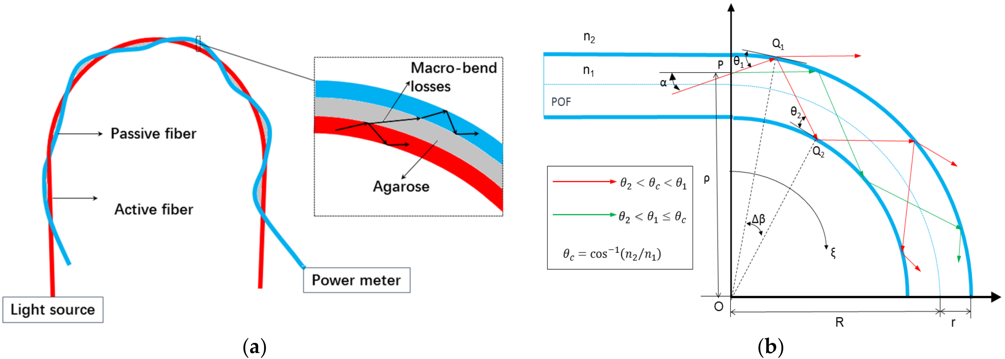
2. Working Principle
3. Sensor Fabrication and Experimental Setup
3.1. Probe Fabrication
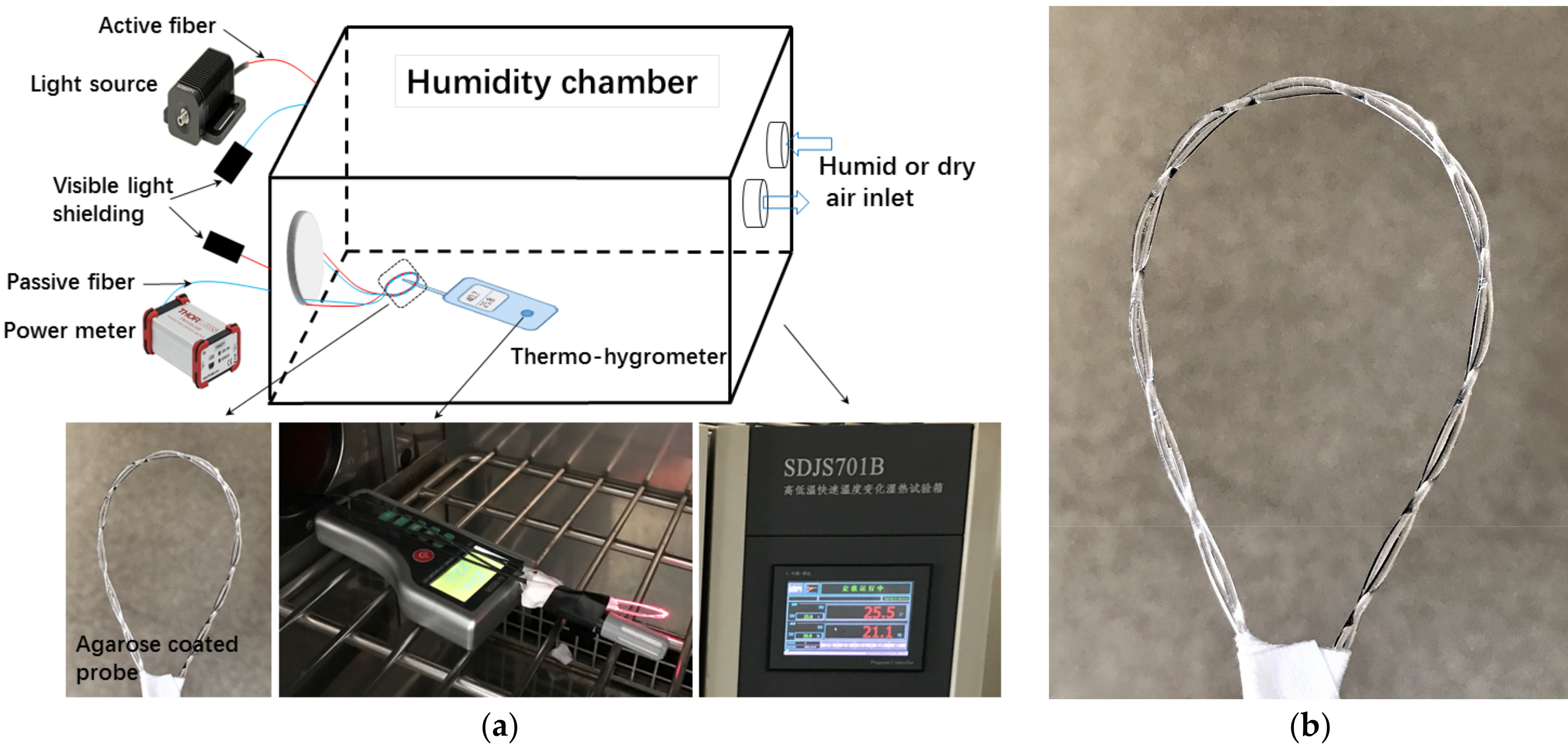
3.2. Experimental Setup for Measurement
4. Results and Discussion
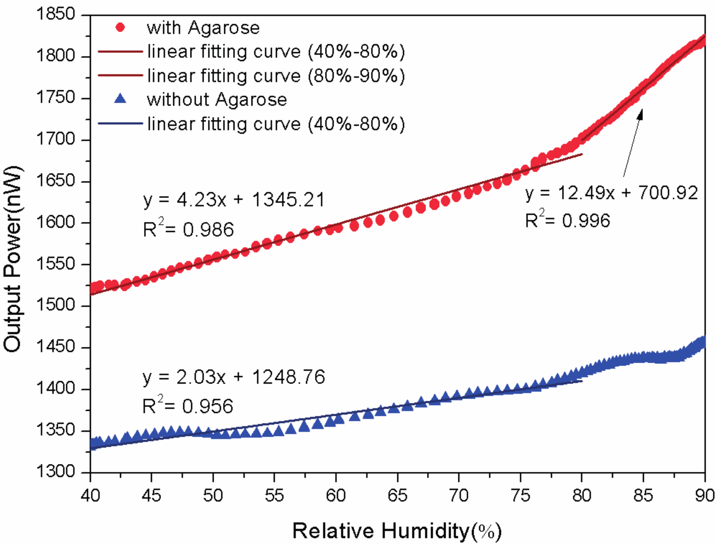
4.1. With or Without Agarose
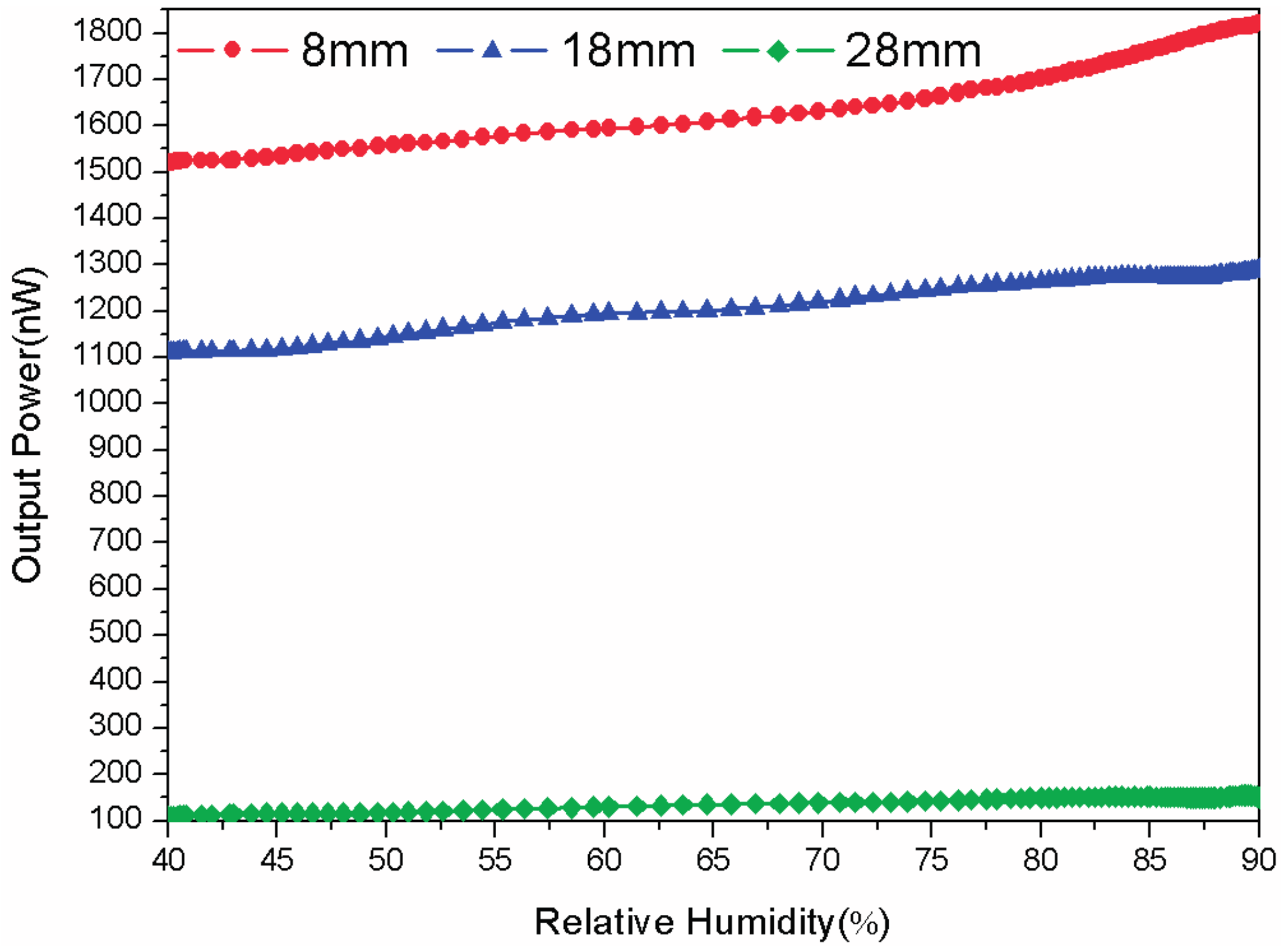
4.2. Different Radiuses
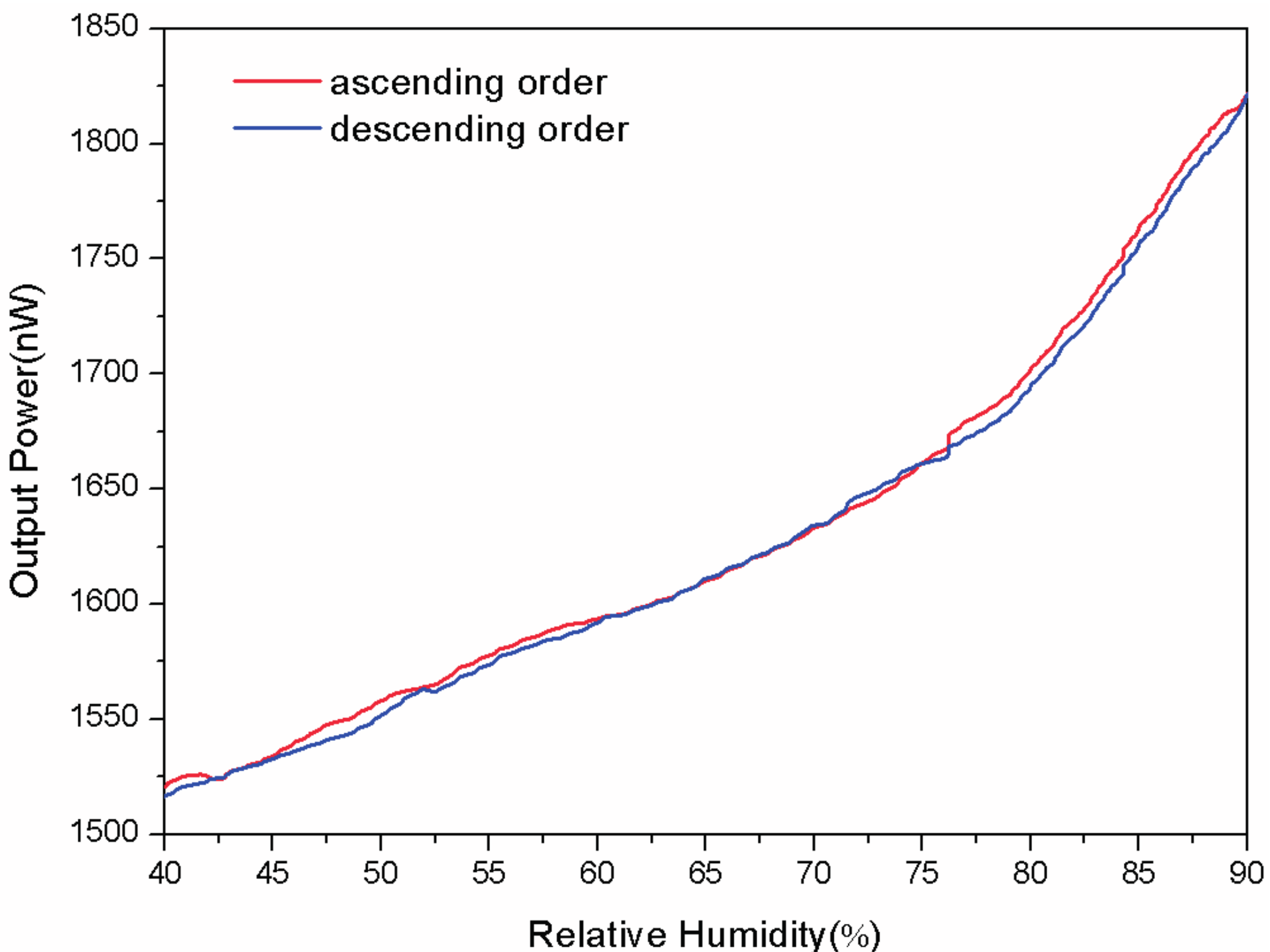
4.3. Reversibility
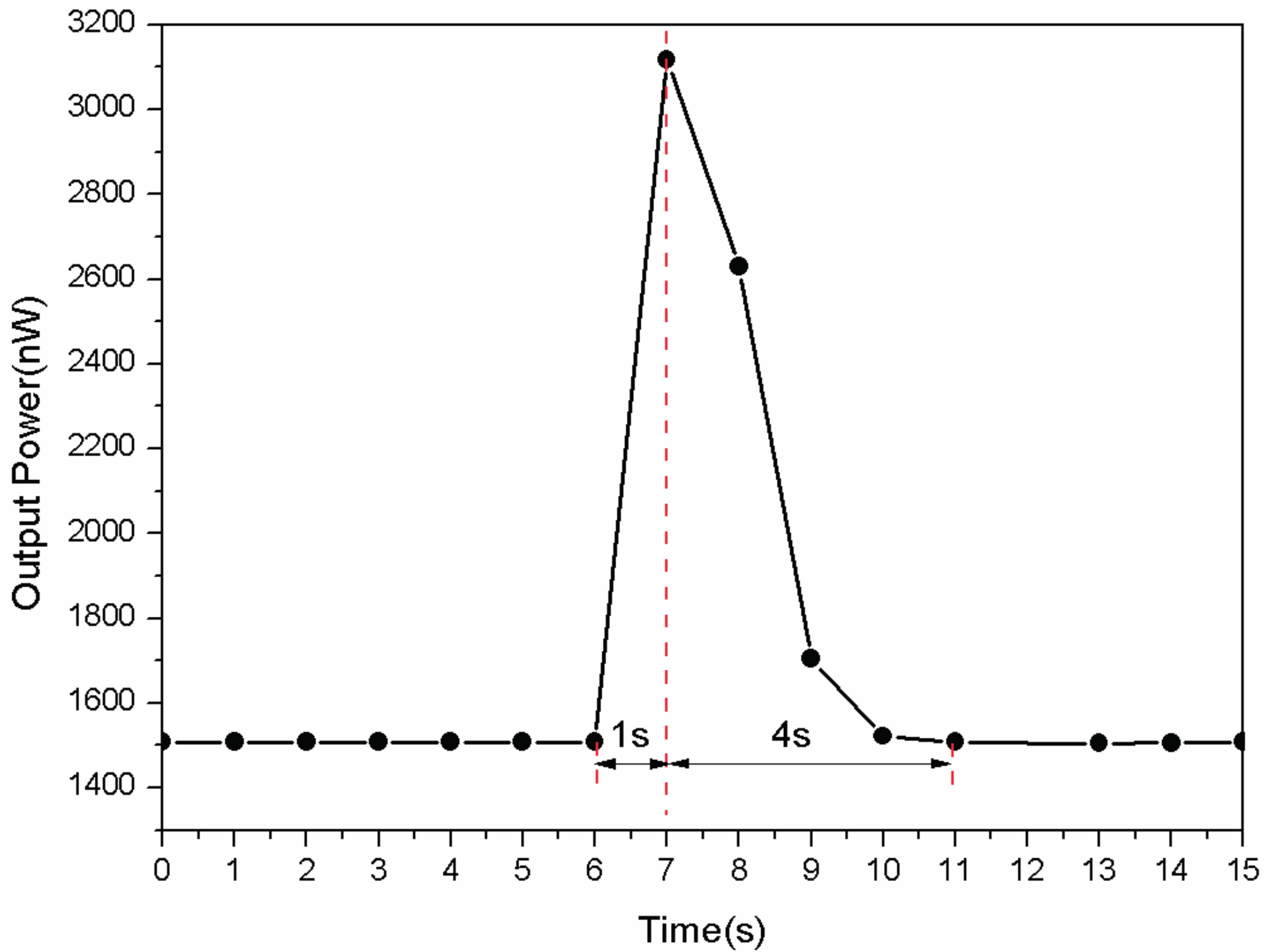
4.4. Response Time
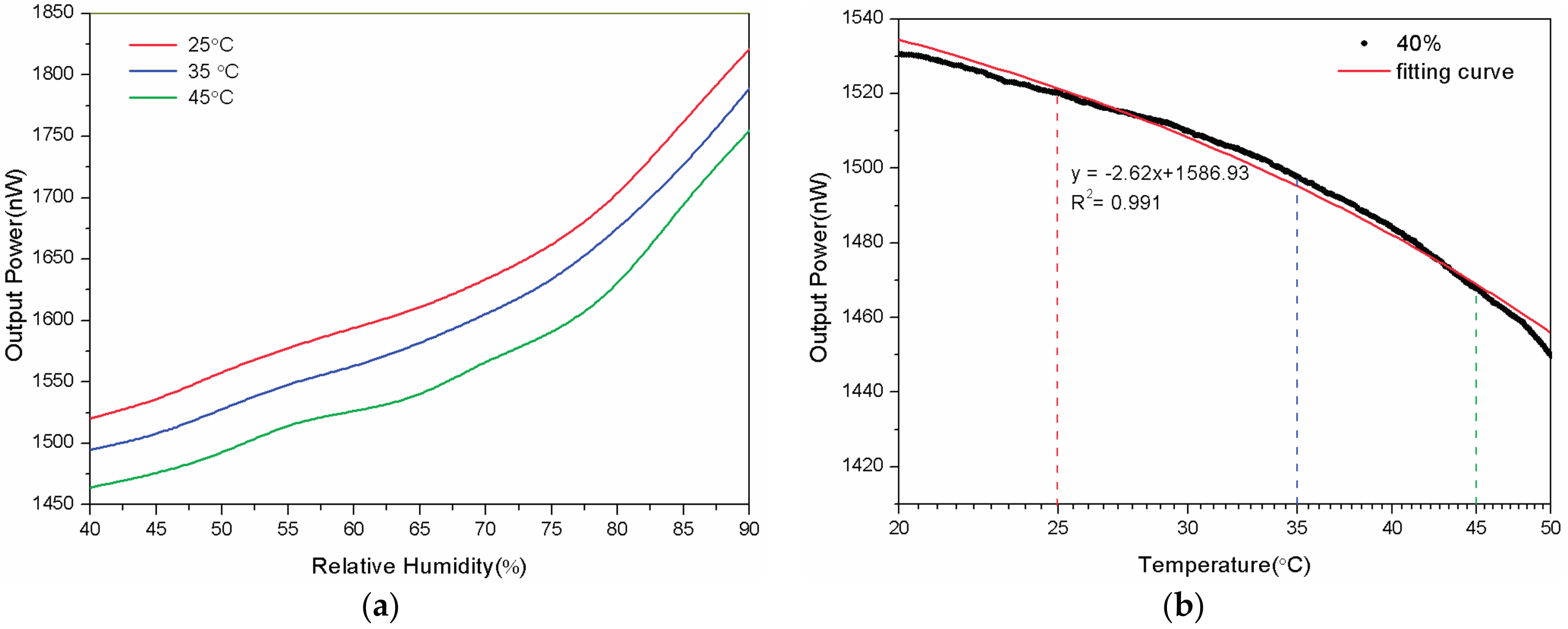
4.5. Temperature Dependence
5. Conclusions
Acknowledgments
Author Contributions
Conflicts of Interest
References
- Zhang, D.; Chang, H.; Li, P.; Liu, R.; Xue, Q. Fabrication and characterization of an ultrasensitive humidity sensor based on metal oxide/graphene hybrid nanocomposite. Sens. Actuators B Chem. 2016, 225, 233–240. [Google Scholar] [CrossRef]
- Liu, M.Q.; Wang, C.; Kim, N.Y. High-sensitivity and low-hysteresis porous mimtype capacitive humidity sensor using functional polymer mixed with TiO2 microparticles. Sensors 2017, 17, 284. [Google Scholar] [CrossRef] [PubMed]
- Matko, V.; Dali, D. Sensor for high-air-humidity measurement. IEEE Trans. Instrum. Meas. 1996, 45, 561–563. [Google Scholar] [CrossRef]
- Matko, V.; Joze, K. Quartz sensor for water absorption measurement in glass-fiber resins. IEEE Trans. Instrum. 1998, 47, 1159–1162. [Google Scholar] [CrossRef]
- Zhang, D.; Tong, J.; Xia, B. Humidity-sensing properties of chemically reduced graphene oxide/polymer nanocomposite film sensor based on layer-by-layer nano self-assembly. Sens. Actuators B Chem. 2014, 197, 66–72. [Google Scholar] [CrossRef]
- Zhang, D.; Tong, J.; Xia, B.; Xue, Q. Ultrahigh performance humidity sensor based on layer-by-layer self-assembly of graphene oxide/polyelectrolyte nanocomposite film. Sens. Actuators B Chem. 2014, 203, 263–270. [Google Scholar] [CrossRef]
- Irani, F.S.; Tunaboylu, B. Saw humidity sensor sensitivity enhancement via electrospraying of silver nanowires. Sensors 2016, 16, 2024. [Google Scholar] [CrossRef] [PubMed]
- Lim, W.H.; Yap, Y.K.; Chong, W.Y.; Ahmad, H. All-optical graphene oxide humidity sensors. Sensors 2014, 14, 24329–24337. [Google Scholar] [CrossRef] [PubMed]
- Ascorbe, J.; Corres, J.M.; Matias, I.R.; Arregui, F.J. High sensitivity humidity sensor based on cladding-etched optical fiber and lossy mode resonances. Sens. Actuators B Chem. 2016, 233, 7–16. [Google Scholar] [CrossRef]
- Gao, R.; Lu, D.-F.; Cheng, J.; Jiang, Y.; Jiang, L.; Qi, Z.-M. Humidity sensor based on power leakage at resonance wavelengths of a hollow core fiber coated with reduced graphene oxide. Sens. Actuators B Chem. 2016, 222, 618–624. [Google Scholar] [CrossRef]
- Wang, Y.; Shen, C.; Lou, W.; Shentu, F. Polarization-dependent humidity sensor based on an in-fiber mach-zehnder interferometer coated with graphene oxide. Sens. Actuators B Chem. 2016, 234, 503–509. [Google Scholar] [CrossRef]
- Bai, W.; Yang, M.; Dai, J.; Yu, H.; Wang, G.; Qi, C. Novel polyimide coated fiber bragg grating sensing network for relative humidity measurements. Opt. Express 2016, 24, 3230–3237. [Google Scholar] [CrossRef] [PubMed]
- Swanson, A.J.; Raymond, S.G.; Janssens, S.; Breukers, R.D.; Bhuiyan, M.D.H.; Lovell-Smith, J.W.; Waterland, M.R. Development of novel polymer coating for fbg based relative humidity sensing. Sens. Actuators A Phys. 2016, 249, 217–224. [Google Scholar] [CrossRef]
- Rajan, G.; Noor, Y.M.; Liu, B.; Ambikairaja, E.; Webb, D.J.; Peng, G.-D. A fast response intrinsic humidity sensor based on an etched singlemode polymer fiber bragg grating. Sens. Actuators A Phys. 2013, 203, 107–111. [Google Scholar] [CrossRef]
- Luo, Y.; Chen, C.; Xia, K.; Peng, S.; Guan, H.; Tang, J.; Lu, H.; Yu, J.; Zhang, J.; Xiao, Y.; et al. Tungsten disulfide (WS2) based all-fiber-optic humidity sensor. Opt. Express 2016, 24, 8956–8966. [Google Scholar] [CrossRef] [PubMed]
- Xiao, Y.; Zhang, J.; Cai, X.; Tan, S.; Yu, J.; Lu, H.; Luo, Y.; Liao, G.; Li, S.; Tang, J.; et al. Reduced graphene oxide for fiber-optic humidity sensing. Opt. Express 2014, 22, 31555–31567. [Google Scholar] [CrossRef] [PubMed]
- Batumalay, M.; Lokman, A.; Ahmad, F.; Arof, H.; Ahmad, H.; Harun, S.W. Tapered plastic optical fiber coated with HEC/PVDF for measurement of relative humidity. IEEE Sens. J. 2013, 13, 4702–4705. [Google Scholar] [CrossRef]
- Jing, N.; Teng, C.; Zhao, X.; Zheng, J. Temperature dependence of a refractive index sensor based on a macrobending micro-plastic optical fiber. Appl. Opt. 2015, 54, 1890–1893. [Google Scholar] [CrossRef] [PubMed]
- Hou, Y.-L.; Liu, W.-Y.; Su, S.; Zhang, H.-X.; Zhang, J.-W.; Liu, J.; Xiong, J.-J. Polymer optical fiber twisted macro-bend coupling system for liquid level detection. Opt. Express 2014, 22, 23231–23241. [Google Scholar] [CrossRef] [PubMed]
- Liu, J.; Hou, Y.; Zhang, H.; Jia, P.; Su, S.; Fang, G.; Liu, W.; Xiong, J. A wide-range displacement sensor based on plastic fiber macro-bend coupling. Sensors 2017, 17, 196. [Google Scholar] [CrossRef] [PubMed]
- Batumalay, M.; Harun, S.W.; Irawati, N.; Ahmad, H.; Arof, H. A study of relative humidity fiber-optic sensors. IEEE Sens. J. 2015, 15, 1945–1950. [Google Scholar] [CrossRef]
- Gao, R.; Jiang, Y.; Ding, W. Agarose gel filled temperature-insensitive photonic crystal fibers humidity sensor based on the tunable coupling ratio. Sens. Actuators B Chem. 2014, 195, 313–319. [Google Scholar] [CrossRef]
- Jing, N.; Zheng, J.; Zhao, X.; Teng, C. Investigation of a macrobending micro-plastic optical fiber for refractive index sensing. Appl. Opt. 2014, 53, 8145–8150. [Google Scholar] [CrossRef] [PubMed]
- Mathew, J.; Semenova, Y.; Farrell, G. A fiber bend based humidity sensor with a wide linear range and fast measurement speed. Sens. Actuators A Phys. 2012, 174, 47–51. [Google Scholar] [CrossRef]


| Performances | With Agarose | Without Agarose |
|---|---|---|
| Sensitivity (nW/%) | 4.23 | 1.49 |
| Linearity (%) | 99.30 | 80.00 |
| Std deviation (nW) | 2.98 | 4.35 |
| Limit of detection (%) | 0.70 | 2.92 |
| Reference | Structure of Fiber | Coating Material | Sensitivity | Sensing Range (%) | Response Time (s) |
|---|---|---|---|---|---|
| This paper | Twisted macro-bend coupling structure | Agarose | 4.23 nW/% | 40–90 | 1 |
| [13] | Singlemode polymer fiber Bragg | None | 0.23 mV/% | 10–90 | 4.5 |
| [14] | Side polished fiber | WS2 film | 0.1213 dB/% | 35–85 | 1 |
| [15] | Side polished fiber | Reduced graphene oxide | 0.31 dB/% | 70–95 | 5 |
| [16] | Tapered POF | HEC/PVDF | 0.023 mV/% | 50–85 | none |
| [20] | Tapered POF | ZnO | 0.0258 mV/% | 50–85 | none |
| [20] | Tapered POF | Agarose | 0.0228 mV/% | 50–85 | none |
© 2017 by the authors. Licensee MDPI, Basel, Switzerland. This article is an open access article distributed under the terms and conditions of the Creative Commons Attribution (CC BY) license (http://creativecommons.org/licenses/by/4.0/).
Share and Cite
Zhang, Y.; Hou, Y.; Liu, W.; Zhang, H.; Zhang, Y.; Zhang, Z.; Guo, J.; Liu, J.; Zhang, L.; Tan, Q.-l. A Cost-Effective Relative Humidity Sensor Based on Side Coupling Induction Technology. Sensors 2017, 17, 944. https://doi.org/10.3390/s17050944
Zhang Y, Hou Y, Liu W, Zhang H, Zhang Y, Zhang Z, Guo J, Liu J, Zhang L, Tan Q-l. A Cost-Effective Relative Humidity Sensor Based on Side Coupling Induction Technology. Sensors. 2017; 17(5):944. https://doi.org/10.3390/s17050944
Chicago/Turabian StyleZhang, Yingzi, Yulong Hou, Wenyi Liu, Huixin Zhang, Yanjun Zhang, Zhidong Zhang, Jing Guo, Jia Liu, Liang Zhang, and Qiu-lin Tan. 2017. "A Cost-Effective Relative Humidity Sensor Based on Side Coupling Induction Technology" Sensors 17, no. 5: 944. https://doi.org/10.3390/s17050944