Parameterized Pseudo-Localization for Accurate and Efficient Moving Targets Imaging in Synthetic Aperture Radar

1
Qian Xuesen Laboratory of Space Technology, Beijing 100094, China
2
School of Electronic Engineering, University of Electronic Science and Technology of China, Chengdu 611731, China
*
Author to whom correspondence should be addressed.
Sensors 2017, 17(8), 1714; https://doi.org/10.3390/s17081714
Submission received: 7 June 2017
/
Revised: 10 July 2017
/
Accepted: 19 July 2017
/
Published: 26 July 2017
(This article belongs to the Section Remote Sensors)
Abstract
:Accurate and efficient moving target imaging is an important challenge for targets recognition in current synthetic aperture radar (SAR) combined with a ground moving target indication (GMTI) system. As the key but unknown parameter, the Doppler rates are estimated conventionally by searching any possible values for moving targets imaging. However, this conventional estimation method suffers from low accuracy or low efficiency due to the searching procedure. Focusing on these, we present a method to efficiently image the moving targets without the Doppler rate by Doppler delayed interferometry, and the imaged localization, which is parameterized pseudo-localization, is used to estimate the Doppler rate. In order to improve the estimation accuracy, an improved method based on the Newton method of approximation is proposed by exploiting the unused amplitude information. Compared with the conventional methods, the proposed improved method capable of high accuracy and low computation complexity simultaneously can meet the accurate and efficient requirements in the practical applications. Comparison simulations and real data processing results demonstrate the effectiveness of the proposed methods.
1. Introduction
Characterized by high resolution, cloud penetration, and remote sensing capabilities, synthetic aperture radar (SAR) has been studied intensively in both civil and military applications in recent years [1,2,3,4,5,6]. Combined with ground moving targets indication (GMTI) techniques, SAR-GMTI has been developed to be an effective and convenient way to realize moving target localization and recognition in the well-focused image domain [7,8,9,10,11,12]. In this case, the accurate focusing of the moving target becomes the most important prerequisite. It is well known that the focusing quality of the moving target is affected by the estimated Doppler rate [13]. A mismatch between the estimated Doppler rate and its real value not only causes severe blurring of the image but also degrades the target detection and localization performance [14]. Thus, accurate Doppler rate estimation is strongly desirable.
Composed of different Doppler rates due to different azimuth velocities [12], matched filter banks [15] are used in the range-Doppler algorithm (RDA) for moving target imaging. Image the moving target by any possible Doppler rate, and the one corresponding to the best focused result is selected as the Doppler rate of the moving target. Similar to matched filter banks, a time-frequency distribution that is expert in representing the modulate signal is often used to estimate the Doppler rate [14]. The fractional Fourier transform [16,17,18,19] and the Radon-Wigner distribution [19,20] can realize the Doppler rate estimation by searching all possible parameters. All of these conventional methods can be classified as being the search-based methods. However, the search-based methods are confronted with the following bottlenecks: (1) huge computation complexity due to searching all possible parameters; (2) when searching step size selection, there is a compromise when considering high estimation accuracy (due to small searching step size) and low computation complexity (introduced by large searching step size). These bottlenecks restrict the development of the search-based methods in practical applications, especially for the requirements of high real-time and high estimation accuracy. Summarily, the Doppler rate should be estimated as having high efficiency along with high accuracy.
Focusing on these, we present an efficient method to image the moving target without the Doppler rate, which is very different from the existing methods. Moreover, the imaged localization by the proposed method is parameterized pseudo-localization, which can be used to estimate the Doppler rate. In order to improve the estimation accuracy, we propose an improved method utilizing the Newton method of approximation by exploiting the unused amplitude information. Theoretical derivation and experiments results demonstrate the proposed methods with high accuracy and low computational complexity.
2. Signal Model for Moving Target in SAR System
After the range compression, the signal of the moving target can be expressed as
where is the radar cross section, and denote the bandwidth and the carrier frequency of the transmitted linear frequency modulated signal, respectively, and represent the fast time and slow time. The radar platform keeps constant azimuth velocity in the synthetic aperture time , the moving target locates in the coordinate of at , the radial velocity and the azimuth velocity of the moving target is also supposed to be constant in .
Since the range walk due to the radial velocity of the moving target seriously affects the azimuth processing, we adopt the keystone transform [21,22] to compensate for the range walk. In order to realize the keystone transform, the range compression result (1) is transformed into the range frequency domain by the fast Fourier transform (FFT) in the range
The following relationship
is substituted into (2), and then we can obtain
Using the following approximation [23]
(4) can be rewritten as
In order to compensate for the range curve effect, we adopt the following procedure
Applying the inverse FFT (IFFT) in range, the range compression result after range walk and curve correction can be written as
where the approximation holds because
It can be seen from (8) that the Doppler rate of the moving target
is unknown because of its unknown . Since the Doppler rate of the moving target is different from that of the stationary targets (or scenery), the moving target would be defocused when imaging the scenery with the Doppler rate of stationary targets. It is known that the Doppler rate plays an important role in not only moving target imaging but also the azimuth velocity estimation, both of which can be used for moving target recognition. Moreover, the Doppler rate estimation accuracy determines the performance of moving target imaging and velocity estimation. Thus, the Doppler rate should be estimated as accurately as possible.
Conventionally, any possible Doppler rates are used to realize the azimuth compression for moving target imaging, and the one corresponding to the best focused result can be thought as the most accurate estimated Doppler rate. And then the moving target imaging and its azimuth velocity can be obtained. This is the main idea of the conventional Doppler rate estimation method. However, since the matched Doppler rate is searched from all of possible chirp rates, the computation complexity is huge, and the estimation accuracy is seriously affected by the searching step size.
3. The Proposed Parameterized Pseudo-Localization for Efficient Doppler rate Estimation
Focusing on these, we have proposed a new Doppler rate estimation method by using the localization information. Different from the existing searching based method, the proposed method can achieve efficient estimation. Moreover, these existing estimation methods achieve Doppler rate estimation after moving target imaging, while the proposed method realizes moving target imaging inventively without Doppler rate, and the Doppler rate can be estimated from the localization of the imaged moving target.
Without Doppler rate, the moving target cannot be focused well by the range-Doppler algorithm (RDA). Being cognizant of this, we utilize the Doppler delay interferometry (DDI) to eliminate the Doppler rate term, which is derived in detail as follows.
Firstly, the range compression result in (8) is transformed by FFT in azimuth into the Doppler domain as
Its Doppler delayed result can be written as
where denotes the delayed interval in the Doppler domain. Interferometry is usually used to obtain the different information between two signals, and the interferometry SAR (InSAR) [24] is the well-known application by interferometry between two channels: for example, along-track interferometry (ATI) [25,26,27,28] used for moving targets detection or motion estimation, and cross-track interferometry used for digital elevation model [29,30,31]. Here, interferometry is done between (10) and (11) to eliminate the same Doppler rate terms, and then the DDI result can be derived as
where stands for the conjugate of . It can be seen from (12) that the Doppler quadratic term is eliminated by the DDI, which can be thought as the concept of self-match. Since the Doppler rate term is removed, the moving target imaging result can be obtained by the IFFT in azimuth as
By focusing only on the amplitude term related with the azimuth localization, we can rewrite the moving target imaging result into
where denotes the other amplitude terms except the azimuth sinc function. It can be seen from (14) that the original azimuth localization is not contained in (14), that is, it is pseudo-localization. This is because the DDI eliminate the Doppler centroid which including . Optimistically, coins have two sides. The pseudo-localization is determined by the unknown Doppler rate of the moving target , so the Doppler rate of the moving target can be estimated by the pseudo-localization of the moving target via
where is the measured pseudo-localization of the moving target, which corresponds to the max amplitude in the imaging result of (13).
Visually, the estimation accuracy of the Doppler rate is intimately affected by the measurement accuracy of the pseudo-localization. However, since the azimuth resolution is not very high due to the limited Doppler bandwidth, the measured pseudo-localization of the moving target is not accurate, namely,
where denotes the theoretical localization, the function of rounds the elements of to the nearest integer. At that point the Doppler rate can be obtained.
In this section, the proposed method is presented to image the moving targets without the Doppler rate, and its parameterized pseudo-localization is modeled to estimate the Doppler rate efficiently. However, due to the operation, the localization is measured with error, and then the Doppler rate is estimated in low accuracy. In the next section, we will propose an improved method to realize much more accurate localization measurement, and then the Doppler rate can be estimated with much higher accuracy.
4. The Improved Accurate Estimation Method
In order to measure the localization as accurately as possible, we utilize Newton method of approximation by using the amplitude information of the moving target imaging result.
By expanding the sinc function, we can rewrite the moving target imaging result in (14) as
Considering the discrete representation, we can express the slow time by
Since the amplitude term is constant but unknown, we adopt two amplitudes to eliminate the constant term . And the amplitudes can be written by
where and denote the amplitude corresponding to azimuth localization and , respectively. Division between (19) and (20) is done to eliminate through
In order to use the Newton method, the division result of (21) can be rewritten as
Using the Newton method to solve (22), we can obtain the accurate localization by the following iteration
where denotes the differentiate of , represents the th iterated localization, and the original value of can be set as . We can set the terminated condition according to different requirements. For example, the iterated results vary slightly as or the iterated times is large enough, such as . After the iteration is terminated, we can obtain the accurate localization , and then the Doppler rate of the moving target can be calculated by
Since the Newton method can be realized efficiently and accurately, the Doppler rate of the moving target can be estimated by the proposed method with high accuracy and low computation complexity. After obtaining the Doppler rate of the moving target, we can image the moving target by RDA, and then the real localization can be obtained.
Summarily, by exploiting the amplitude information, the proposed improved method simultaneously possesses the advantages of high accuracy and low computational complexity.
5. Experiment Results and Analysis
In this section, the experiments results are presented to demonstrate the effectiveness of the proposed methods. The system parameters are shown in Table 1.
5.1. Moving Target Imaging Comparison between the RDA and the Presented DDI
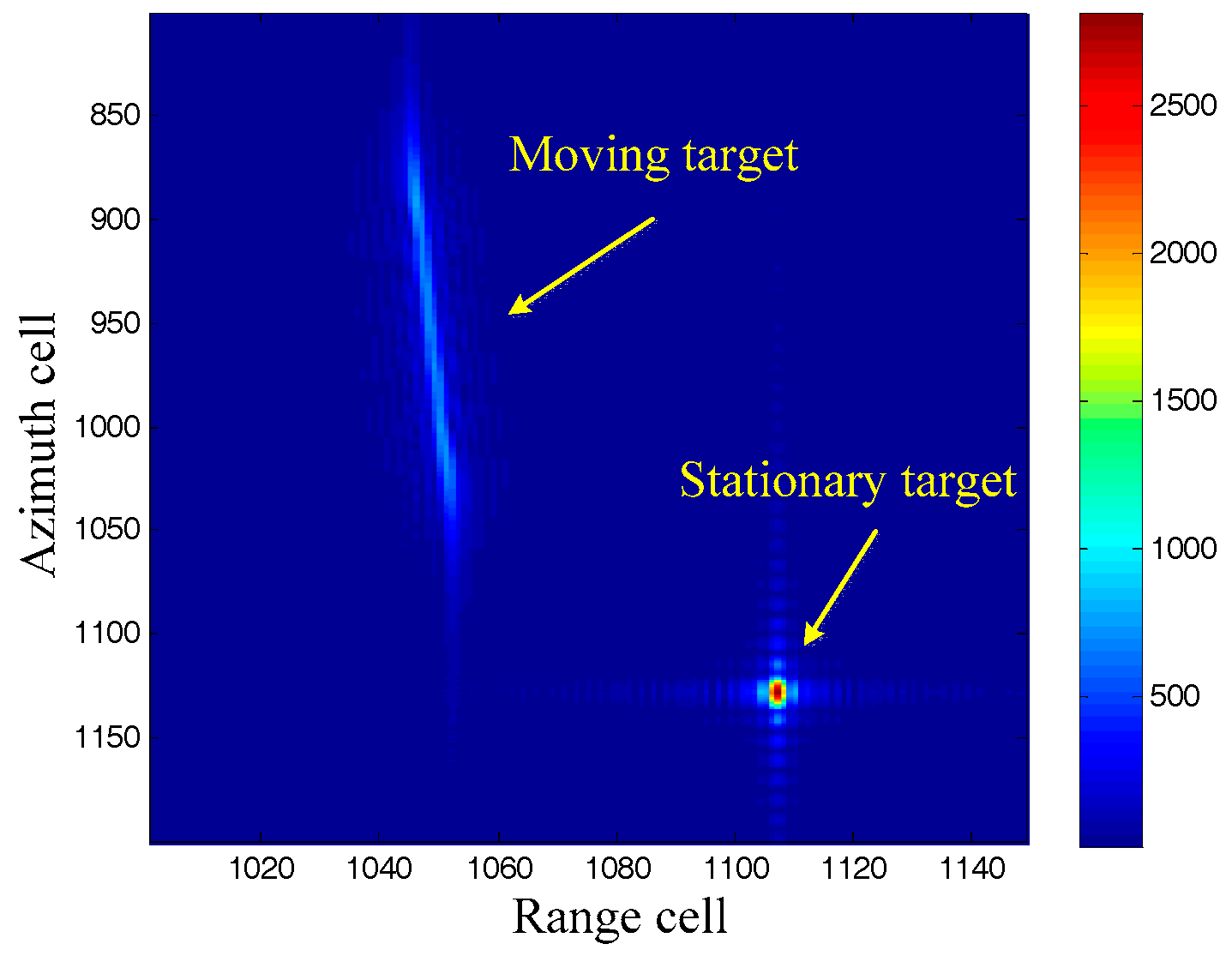
In order to present the advantages of the DDI, we compare the moving targets imaging between the RDA and the DDI in this subsection. A moving target and a stationary target, with the same azimuth localization , are imaged by both the RDA and the DDI. The RDA is realized by using the Doppler rate of the stationary target, which can be easily obtained by the system parameters. The imaging results are shown in Figure 1 and Figure 2.
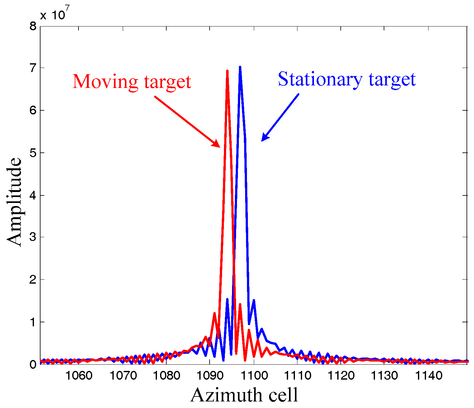
It can be seen from Figure 1 that the stationary target is well focused, while the moving target is badly defocused because of its different Doppler rate. Moreover, the imaging moving target is displaced from its original azimuth localization due to its radial velocity. We will now pay attention to the imaging results by the DDI in Figure 2. Firstly, both of the moving target and the stationary target are focused well, demonstrating that the DDI method can realize focused imaging results with an unknown Doppler rate. Secondly, the amplitudes of the targets imaged by the DDI are much higher than that by the RDA. This is because the DDI enhances the amplitude by the interferometry according to (12), which is very useful for improving the signal to noise ratio (SNR) in practical applications. Thirdly, the azimuth localization of the moving target imaged by the DDI is also displaced from its original localization. The azimuth localization comparison between the moving target and the stationary target, with the same original azimuth localization, is shown as Figure 3.
It can be seen that the azimuth localization of the moving target is different from that of the stationary target, that is, the azimuth localization imaged by DDI is pseudo-localization. This is because the Doppler rates of for them are different from each other, which has been aforementioned in the theoretical derivation. Moreover, the foundation of the Doppler rate estimation by this pseudo-localization has also been well founded.
5.2. Doppler Rate Estimation Performance Comparison
In this subsection, the Doppler rate estimation accuracy versus to the SNR of the echo is simulated. The proposed basic method, the improved method and the conventional fractional Fourier transform (FRFT) are compared to estimate the Doppler rate, with the comparison results shown in Figure 4. It is known that the FRFT can be used to estimate the Doppler rate by searching any possible values, but the estimation accuracy and computational complexity should be a trade-off due to the searching step size. In order to show these properties of the conventional FRFT, we adopt two FRFTs with different searching step sizes: method 1 (FRFT1) with a searching step size of the FRFT order as 0.5, and; method 2 (FRFT2) with a step size of 0.05.
It can be seen from Figure 4a,b that the improved method possesses much higher estimation accuracy than the basic method, but with almost the same computational complexity. This is because the basic method estimates the Doppler rate by using integer localization, while the improved method can utilize much more accurate localization obtained by the Newton method without the complexity burden increasing. The following trade-off properties of the conventional FRFT methods can be seen from Figure 4: a large step size brings low complexity with low accuracy, while small step size brings high accuracy with high complexity. Compared with the conventional FRFT methods, the basic method possesses much higher efficiency with much lower accuracy, while the improved method presents much better in both terms of estimation and computational complexity, which shows the advantages of the proposed improved method.
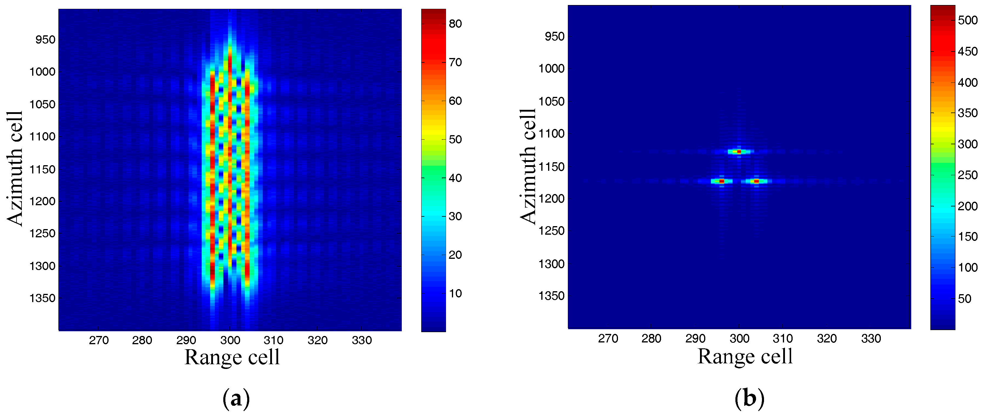
After Doppler rate estimation, we focus on moving targets imaging results by the estimated Doppler rate. A moving target with three scatters is simulated to demonstrate the effectiveness of the proposed method in moving target imaging and recognition, and its azimuth velocity is set as 20 m/s with radial velocity of zero. The RDA is done with the Doppler rate obtained by the stationary parameters, and the proposed improved method is used to estimate the Doppler rate first, then the RDA is used to re-image the moving target with the estimated Doppler rate, with the results shown in Figure 5.
It can be seen from Figure 5a that the moving target imaging results by the RDA with Doppler rate of stationary parameters is unfocused with low energy in its spread along azimuth cells. And the re-imaging results are well focused due to the well-estimated Doppler rate by the proposed improved method, which can be used for the targets recognition.
5.3. Real Data Process
Real data is processed to further demonstrate the effectiveness of the proposed method. The system parameters are listed in Table 1. The clutter suppression result by the extended factored approach [32,33,34] in the range-Doppler domain is shown as Figure 6. The moving targets are easy to detect. Moreover, the range walk due to the radial velocity of the moving targets appears in Figure 6, which should be corrected to guarantee the moving targets imaging. As aforementioned, the keystone transform is used to realize the range walk correction, with the results shown in Figure 7. It can be seen that the range walk is effectively corrected for moving target A, while the same consequence does not occur for moving target B. This is because the used keystone transform is valid for the targets with the unambiguous radial velocities but invalid for those with ambiguous radial velocities (for example, moving target B).
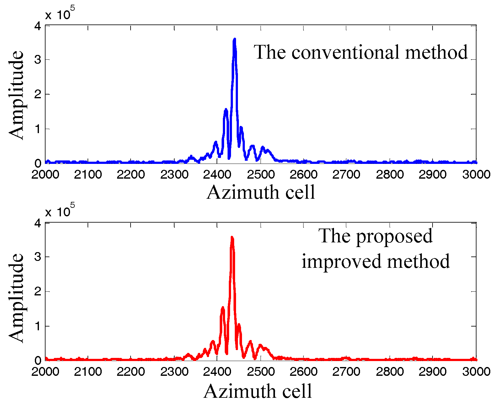
Let us take the moving target A as an example. The proposed improved method and the conventional method are used to estimate the Doppler rate, with the estimation results of and , respectively. The Doppler rate estimation results are used to reimage the moving target A by the RDA, and the imaging results are compared in Figure 8. It can be seen that the imaging results are similar to each other, which concludes that the proposed method is effective in the real scenarios.
6. Conclusions
In this paper, we have proposed a parametrized pseudo-localization based Doppler rate estimation to realize moving targets imaging in high accuracy and low computational complexity. The proposed basic method can image the moving targets without the Doppler rate, and the imaged localization derived as the parameterized pseudo-localization can be used to estimate the Doppler rate in low computational complexity. The improved method is proposed to improve the estimation accuracy. The amplitude information of the imaged results is exploited, and the Newton method of approximation is used to obtain the Doppler rate with much higher accuracy. The advantages of the proposed methods are validated by the comparison experiments results. Compared with the conventional estimation methods, the proposed methods with high accuracy and low computation load can meet the accuracy and efficiency requirements of practical applications.
Acknowledgments
This work was supported by the Self-dependent Innovation Project of Qian Xuesen Laboratory of Space Technology and the National Natural Science Foundation of China (Grant No. 61401022, No. 61501068).
Author Contributions
Xuepan Zhang proposed the methods, performed the experiments and wrote the paper; Lu Liu gave some suggestions for the improved method; Xuejing Zhang provides important suggestions for improving the paper.
Conflicts of Interest
The authors declare no conflict of interest.
References
- Gierull, C.H.; Sikaneta, I.; Cerutti-Maori, D. Two-Step Detector for RADARSAT-2′s Experimental GMTI Mode. IEEE Trans. Geosci. Remote Sens. 2013, 51, 436–454. [Google Scholar] [CrossRef]
- Zhu, S.; Liao, G.; Qu, Y.; Liu, X.; Zhou, Z. A new slant-range velocity ambiguity resolving approach of fast moving targets for SAR system. IEEE Trans. Geosci. Remote Sens. 2010, 48, 432–451. [Google Scholar]
- Deng, B.; Li, X.; Wang, H.; Qin, Y.; Wang, J. Fast Raw-Signal Simulation of Extended Scenes for Missile-Borne SAR with Constant Acceleration. IEEE Geosci. Remote Sens. Lett. 2011, 8, 44–48. [Google Scholar] [CrossRef]
- Gierull, C.H. Analysis of the Multimode Feedhorn Concept for Multichannel SAR-GMTI. IEEE Trans. Geosci. Remote Sens. 2011, 49, 3611–3621. [Google Scholar] [CrossRef]
- Tan, W.; Xu, W.; Huang, P.; Huang, Z.; Qi, Y.; Han, K. Investigation of Azimuth Multichannel Reconstruction for Moving Targets in High Resolution Wide Swath SAR. Sensors 2017, 17, 1270. [Google Scholar] [CrossRef] [PubMed]
- Yuan, Y.; Chen, S.; Zhao, H. An Improved RD Algorithm for Maneuvering Bistatic Forward-Looking SAR Imaging with a Fixed Transmitter. Sensors 2017, 17, 1152. [Google Scholar] [CrossRef] [PubMed]
- Zhang, B.; Wang, C.; Zhang, H.; Wu, F.; Tang, Y. Detectability Analysis of Road Vehicles in Radarsat-2 Fully Polarimetric SAR Images for Traffic Monitoring. Sensors 2017, 17, 298. [Google Scholar] [CrossRef] [PubMed]
- Xu, J.; Huang, Z.; Yan, L.; Zhou, X.; Zhang, F.; Long, T. SAR Ground Moving Target Indication Based on Relative Residue of DPCA Processing. Sensors 2016, 16, 1676. [Google Scholar] [CrossRef] [PubMed]
- Jing, K.; Xu, J.; Huang, Z.; Yao, D.; Long, T. GMTI for Squint Looking XTI-SAR with Rotatable Forward-Looking Array. Sensors 2016, 16, 873. [Google Scholar] [CrossRef] [PubMed]
- Ender, J.H.G.; Gierull, C.H.; Cerutti-Maori, D. Improved Space-Based Moving Target Indication via Alternate Transmission and Receiver Switching. IEEE Trans. Geosci. Remote Sens. 2008, 46, 3960–3974. [Google Scholar] [CrossRef]
- Li, G.; Xu, J.; Peng, Y.N.; Xia, X.G. Location and Imaging of Moving Targets using Nonuniform Linear Antenna Array SAR. IEEE Trans. Aerosp. Electron. Syst. 2007, 43, 1214–1220. [Google Scholar]
- Li, G.; Xia, X.G.; Xu, J.; Peng, Y.N. A Velocity Estimation Algorithm of Moving Targets using Single Antenna SAR. IEEE Trans. Aerosp. Electron. Syst. 2009, 45, 1052–1062. [Google Scholar] [CrossRef]
- Kirscht, M. Detection and imaging of arbitrarily moving targets with single-channel SAR. In Proceedings of the 2002 International Radar Conference, Edinburgh, UK, 15–17 October 2002. [Google Scholar]
- Jeong-Won, P.; Joong-Sun, W. An Efficient Method of Doppler Parameter Estimation in the Time-Frequency Domain for a Moving Object from TerraSAR-X Data. IEEE Trans. Geosci. Remote Sens. 2011, 49, 4771–4787. [Google Scholar] [CrossRef]
- Gierull, C.H. Ground moving target parameter estimation for two-channel SAR. IEE Proc. Radar Sonar Navig. 2006, 153, 224–233. [Google Scholar] [CrossRef]
- Sun, G.C.; Xing, M.; Xia, X.G.; Yang, J.; Wu, Y.; Bao, Z. A Unified Focusing Algorithm for Several Modes of SAR Based on FrFT. IEEE Trans. Geosci. Remote Sens. 2013, 51, 3139–3159. [Google Scholar] [CrossRef]
- Guan, J.; Chen, X.L.; Huang, Y.; He, Y. Adaptive fractional Fourier transform-based detection algorithm for moving target in heavy sea clutter. IET Radar Sonar Navig. 2012, 6, 389–401. [Google Scholar] [CrossRef]
- Sun, H.-B.; Liu, G.-S.; Gu, H.; Su, W.M. Application of the fractional Fourier transform to moving target detection in airborne SAR. IEEE Trans. Aerosp. Electron. Syst. 2002, 38, 1416–1424. [Google Scholar]
- Wood, J.C.; Barry, D.T. Linear signal synthesis using the Radon-Wigner transform. IEEE Trans. Signal Process. 1994, 42, 2105–2111. [Google Scholar] [CrossRef]
- Wood, J.C.; Barry, D.T. Radon transformation of time-frequency distributions for analysis of multicomponent signals. IEEE Trans. Signal Process. 1994, 42, 3166–3177. [Google Scholar] [CrossRef]
- Zhu, D.; Li, Y.; Zhu, Z. A Keystone Transform without Interpolation for SAR Ground Moving-Target Imaging. IEEE Geosci. Remote Sens. Lett. 2007, 4, 18–22. [Google Scholar] [CrossRef]
- Li, G.; Xia, X.G.; Peng, Y.N. Doppler Keystone Transform: An Approach Suitable for Parallel Implementation of SAR Moving Target Imaging. IEEE Geosci. Remote Sens. Lett. 2008, 5, 573–577. [Google Scholar] [CrossRef]
- Liu, B.; Wang, T.; Bao, Z. Doppler Ambiguity Resolving in Compressed Azimuth Time and Range Frequency Domain. IEEE Trans. Geosci. Remote Sens. 2008, 46, 3444–3458. [Google Scholar] [CrossRef]
- Bamler, R.; Hartl, P. Synthetic aperture radar interferometry. Inverse Probl. 1998, 14, R1–R54. [Google Scholar] [CrossRef]
- Budillon, A.; Evangelista, A.; Schirinzi, G. GLRT Detection of Moving Targets via Multibaseline Along-Track Interferometric SAR Systems. IEEE Geosci. Remote Sens. Lett. 2012, 9, 348–352. [Google Scholar] [CrossRef]
- Budillon, A.; Pascazio, V.; Schirinzi, G. Estimation of Radial Velocity of Moving Targets by Along-Track Interferometric SAR Systems. IEEE Geosci. Remote Sens. Lett. 2008, 5, 349–353. [Google Scholar] [CrossRef]
- Jong-Sen, L.; Hoppel, K.W.; Mango, S.A.; Miller, A.R. Intensity and phase statistics of multilook polarimetric and interferometric SAR imagery. IEEE Trans. Geosci. Remote Sens. 1994, 32, 1017–1028. [Google Scholar] [CrossRef]
- Yoshida, T.; Rheem, C.-K. Time-Domain Simulation of Along-Track Interferometric SAR for Moving Ocean Surfaces. Sensors 2015, 15, 13644–13659. [Google Scholar] [CrossRef] [PubMed]
- Massonnet, D.; Feigl, K.L. Radar interferometry and its application to changes in the earth’s surface. Rev. Geophys. 1998, 36, 441–500. [Google Scholar] [CrossRef]
- Burgmann, R.; Rosen, P.A.; Fielding, E.J. Synthetic aperture radar interferometry to measure Earth’s surface topography and its deformation. Annu. Rev. Earth Planet. Sci. 2000, 28, 169–209. [Google Scholar] [CrossRef]
- Zhou, X.; Chang, N.; Li, S. Applications of SAR Interferometry in Earth and Environmental Science Research. Sensors 2009, 9, 1876–1912. [Google Scholar] [CrossRef] [PubMed]
- DiPietro, R.C. Extended factored space-time processing for airborne radar systems. In Proceedings of the 26th Asilomar Conference on Signals, Systems and Computers, Pacific Grove, CA, USA, 26–28 October 1992; Volume 1, pp. 425–430. [Google Scholar]
- Zhang, X.P.; Liao, G.S.; Zhu, S.Q.; Gao, Y.C.; Xu, J.W. Geometry Information Aided Efficient Motion Parameters Estimation for Moving Targets Imaging and Location. IEEE Geosci. Remote Sens. Lett. 2015, 12, 155–159. [Google Scholar] [CrossRef]
- Zhang, X.P.; Liao, G.S.; Zhu, S.Q.; Zeng, C.; Shu, Y.X. Geometry Information Aided Efficient Radial Velocity Estimation for Moving Targets Imaging and Location Based on Radon Transform. IEEE Trans. Geosci. Remote Sens. 2015, 53, 1105–1117. [Google Scholar] [CrossRef]
Figure 1.
Imaging results by range-Doppler algorithm (RDA).

Figure 2.
Imaging results by Doppler delay interferometry (DDI).
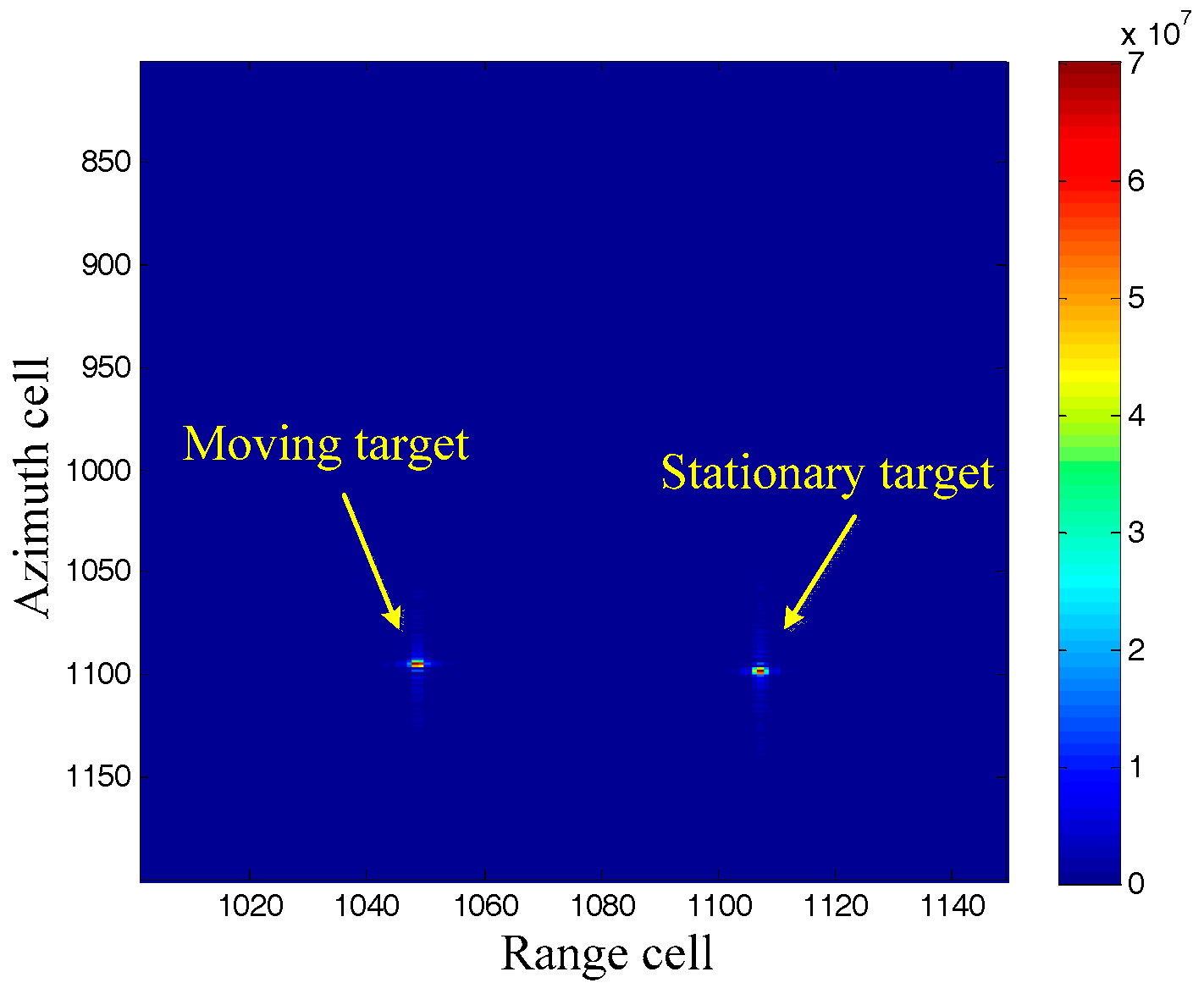
Figure 3.
Azimuth localization comparison.

Figure 4.
Doppler rate estimation comparison results. (a) estimation accuracy comparison; (b) computational complexity comparison.
Figure 4.
Doppler rate estimation comparison results. (a) estimation accuracy comparison; (b) computational complexity comparison.
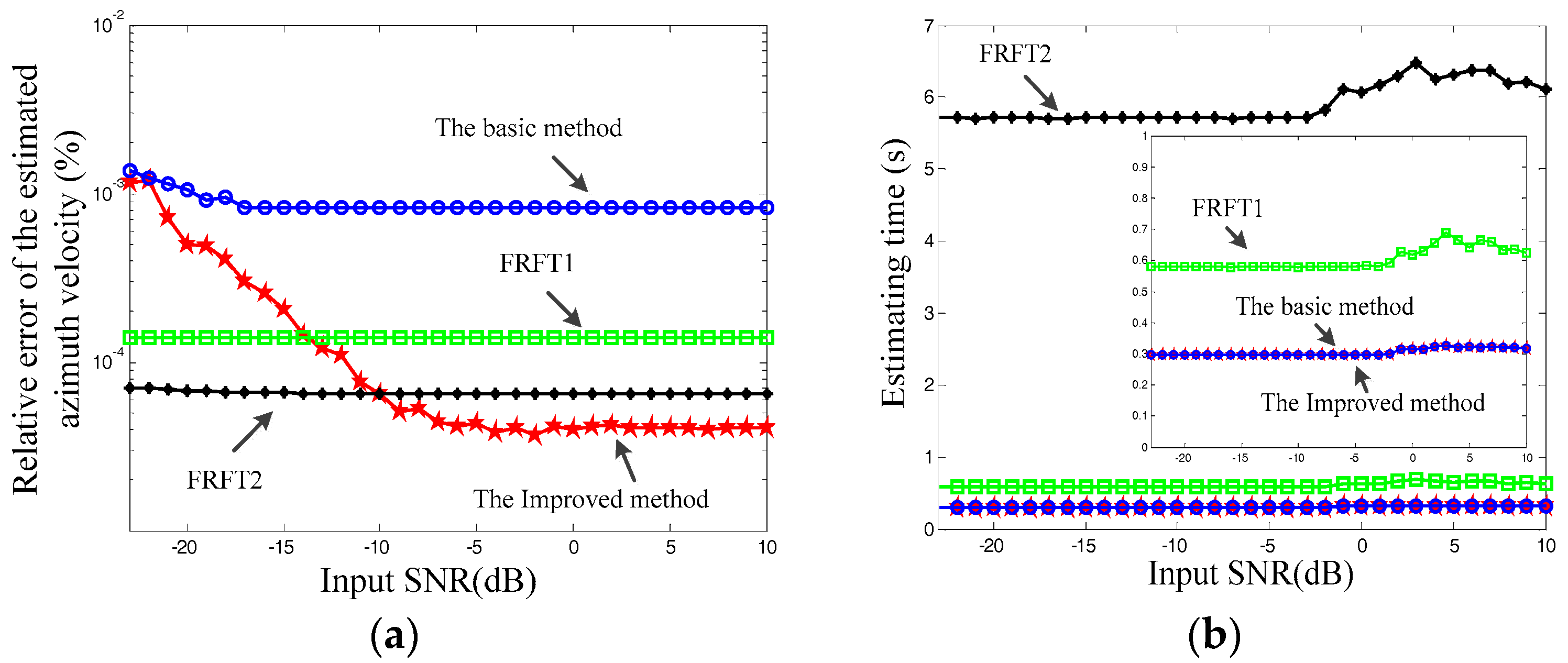
Figure 5.
Moving targets imaging results. (a) by RDA with Doppler rate of stationary parameters, and (b) re-imaging results by the estimated Doppler rate.
Figure 5.
Moving targets imaging results. (a) by RDA with Doppler rate of stationary parameters, and (b) re-imaging results by the estimated Doppler rate.

Figure 6.
Clutter suppression results.
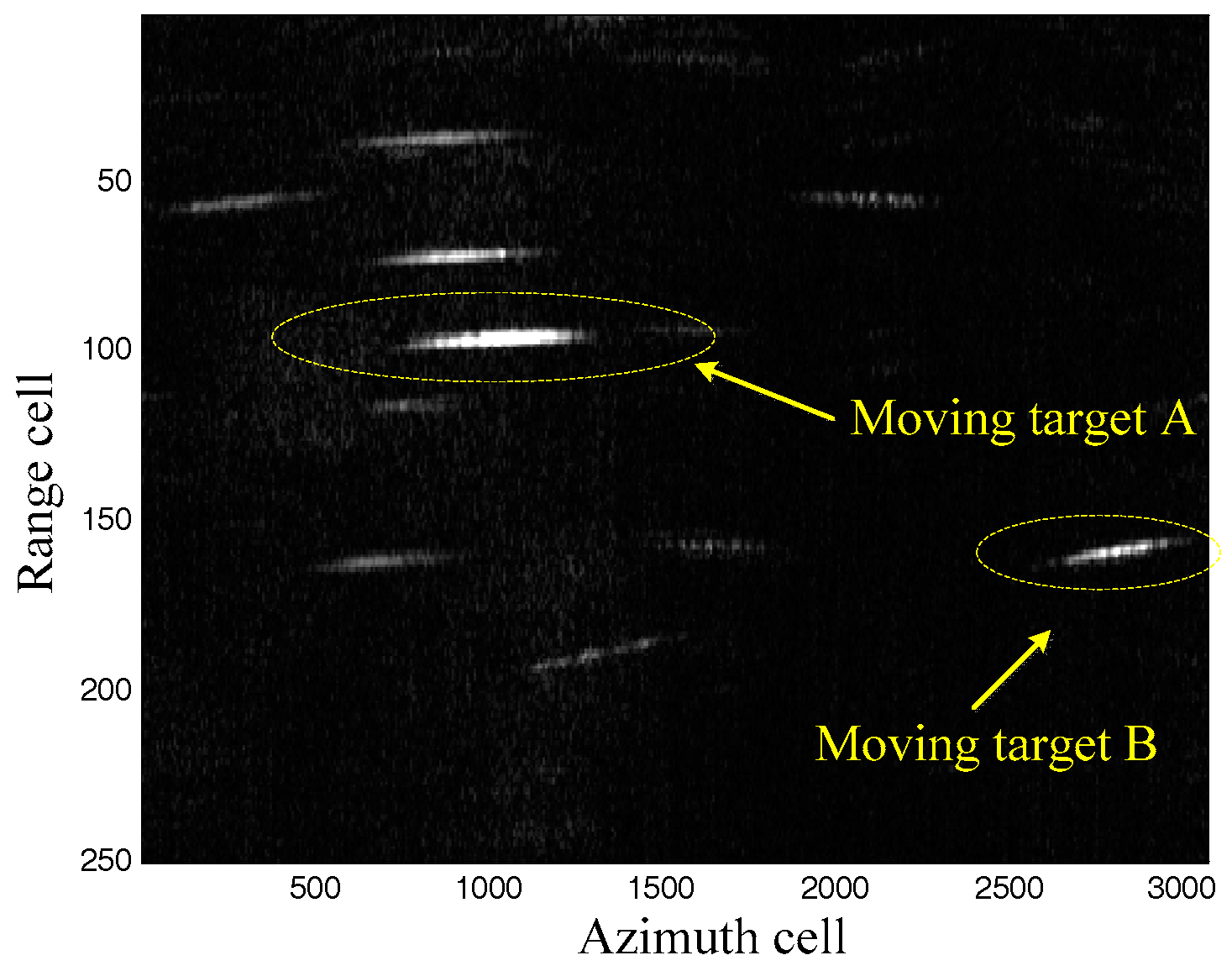
Figure 7.
Keystone transform results.
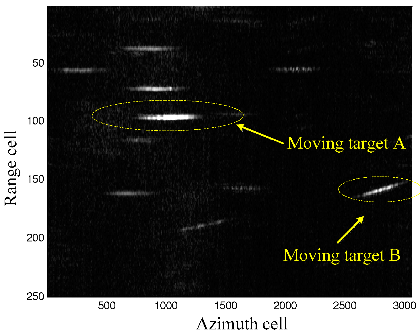
Figure 8.
Moving target imaging results comparison.


Table 1.
System parameters.
| System Parameters | Values |
|---|---|
| Carrier frequency | 8.85 GHz |
| Number of the channels | 3 |
| Channels space | 0.56 m |
| Bandwidth of the transmitted signal | 40 MHz |
| Sampling frequency | 60 MHz |
| Velocity of the platform | 120 m/s |
| Pulse repetition frequency | 1000 Hz |
| Nearest slant range | 9000 m |
© 2017 by the authors. Licensee MDPI, Basel, Switzerland. This article is an open access article distributed under the terms and conditions of the Creative Commons Attribution (CC BY) license (http://creativecommons.org/licenses/by/4.0/).
Share and Cite
MDPI and ACS Style
Zhang, X.; Liu, L.; Zhang, X. Parameterized Pseudo-Localization for Accurate and Efficient Moving Targets Imaging in Synthetic Aperture Radar. Sensors 2017, 17, 1714. https://doi.org/10.3390/s17081714
AMA Style
Zhang X, Liu L, Zhang X. Parameterized Pseudo-Localization for Accurate and Efficient Moving Targets Imaging in Synthetic Aperture Radar. Sensors. 2017; 17(8):1714. https://doi.org/10.3390/s17081714
Chicago/Turabian StyleZhang, Xuepan, Lu Liu, and Xuejing Zhang. 2017. "Parameterized Pseudo-Localization for Accurate and Efficient Moving Targets Imaging in Synthetic Aperture Radar" Sensors 17, no. 8: 1714. https://doi.org/10.3390/s17081714
Note that from the first issue of 2016, this journal uses article numbers instead of page numbers. See further details here.