Impedance Spectroscopy Technique for DNA Hybridization

1
Unité de Recherche de Physique des Semiconducteurs, IPEST, La Marsa, 2070 Tunis, Tunisia
2
Institut National des Sciences Appliquées et de Technologies, Centre Urbain Nord, Bp676, 1080 Charguia Cedex, Tunisia
*
Author to whom correspondence should be addressed.
Sensors 2003, 3(10), 472-479; https://doi.org/10.3390/s31000472
Submission received: 4 August 2003
/
Accepted: 15 September 2003
/
Published: 31 October 2003
Abstract
:The development of biosensors for detection and identification of DNA sequences by hybridization may reduce assay time and allow direct quantitation of the target. This article describes the use of impedance spectroscopy technique for digoxigenin- thiol-labeled ssDNA probe immobilization, anti-digoxigenin binding and targeted DNA hybridization. The analysis of the impedance spectra in terms of equivalents circuits of the gold/electrolyte interface and gold/digoxigenin-thiol-labeled/electrolyte interface is discussed. The DNA hybridization shows a variation in the impedance spectra.
Introduction
DNA hybridization is the noncovalent association of two single stranded (ss) DNA molecules that have complementary nucleotide sequences to form a double-stranded (ds) complex. DNA hybridization is useful as an analytical technique when the nucleotide sequence of one of the members is known, then detection of hybridization allows one to infer the presence of a complementary sequence in a sample of unknown DNA. A common format for the detection of hybridization is to immobilize one strand of DNA on a solid support and then to expose the surface to a solution of the other strand [1,2,3,4,5,6,7,8,9,10,11]. Often the solution-phase DNA strand is coupled to a label, and the accumulation of the label at the surface is evidence of hybridization. Common labels are fluorophores, enzyme substrates, or haptens for antibody binding. The DNA probe may be labelled with a number of small reporter molecules such as digoxigenin. Following hybridization onto the specimen , the labelled DNA is further detected by antibodies (anti-digoxigenin) to the reporter molecule.
The development of biosensors for detection and identification of DNA sequences by hybridization may reduce assay time and allow direct quantitation of the target. Biosensors typically require specific probe molecule to be immobilized adjacent to a transducing element which is capable of converting a physiochemical change into an electrical signal. Transducing elements reported in the literature have included potentiometric, gravimetric, acoustic ant optical devices. Methods reported previously for the detection of the DNA have involved the use of acoustic and optical sensors such as surface plasmon resonance (SPR).
In this work, we use impedance spectroscopy technique for DNA hybridization. First we immobilise one strand with digoxegenin label, and we inject only the anti-digoxigenin. The specific interaction between the biomolecules induce a decrease in the space charge capacitance of gold. Second, we immobilise one strand with the digoxigenin-labeled and we inject the second strand with the anti-digoxigenin, which is the hybridization. A variation in the impedance spectra can be observed.
Experimental
Materials
The following materials were obtained as indicated: DOT(digoxigenin-thiol-labeled ssDNA probe), anti-digoxigenin and complimentary-biotin were obtained from Eurogentec S.A (Spain). Piranha solution (10%(v/v) H2O2; 30%(v/v) H2SO4) was used for cleaning the gold substrate. Buffer hybridization is formed by 10mM tris-HCl, 1mM EDTA and BSA with pH=8. The Millipore water with specific resistance 18.2 MΩcm-1 was employed during all experiment.
Immobilization of DNA probe
The immobilization of DNA probe on to the gold electrodes by chemisorption was carried out by injection of the aqueous solution of 2μg/ml DNA probe having thiol group (DOT) in the surface of the electrode for 4 hours. The gold electrode was rinsed with water to remove all the non-adsorbed DOT.
Hybridization
Hybridization experiments were performed by exposing the fonctionnalized DOT gold substrate to the complementary-biotin 19-mer DNA probes dissolved in the hybridization buffer (10ml tris-HCl, pH=8, 1mM EDTA, 0.3 SSC, 0.2 Denhardt’s). The complimentary DNA was diluted in final concentration of 2μg/ml .The gold electrode was then washed with hybridization buffer..
Impedance Spectroscopy
In a number of reports [12,13,14,15] it has been shown that impedance spectroscopy is a useful tool to characterise the compactness amphiphilic films on solid state surfaces. A capacitor is formed between the conducting electrode and the electrolyte. The frequency dependent capacitance C of the complex stratified surface is related to the absolute value of the complex electric impedance Z (measured in Ohms) by the equation :
where f is the frequency (in Hz) at which is measured.
The surface of the device with a supported film in contact with the aqueous phase exhibits a complex capacitance composed of at least three sub-layers. If the complex impedance Zi of the sub- layers i can be determined by analysis of the measured impedance in terms of an electrical equivalent circuit, the thickness of the sub-layers () can be determined according to equation:
□ is the vaccum dielectric constant (8.85 x10⁻¹⁴ F/cm2), □ is the dielectric constant of the layer i and A is the area of the surface. The impedance analysis was performed with the Voltalab40 impedance analyzer. We plot the impedance modulus |Z(ω)| versus frequency ω, which is sufficient for the discussion of impedance data. For analyzing the measured data, the second polar coordinate of the complex impedance ϕ(ω) is of course considered as well.
To fit the measured spectra with the impedance spectra out of ideal elements, we replaced the ideal elements with the constant phase elements (CPE) :
The frequency exponent is □ = 1 and K = 1/C for an ideal capacitance, and □ = 0 and K = R for an ideal resistance, respectively. The exponent α could be obtained, when the membrane capacitance (or layer capacitance) was replaced by a constant phase element ZCPE. The deviation of the exponent α from the ideal values is attributed to the inhomogeneities of the analyzed layer, like defects or roughness. The measured spectra of the impedance and phase were analyzed in terms of electrical equivalent circuits using an Apple Macintosh and the analysis program IGOR (Wavemetrics, OR). The mathematical expressions of the equivalent circuit models were fitted to the data in terms of the logarithm of the absolute value of the impedance Z(ω)and the phase ϕ(ω) by user defined functions. The electric parameters of the system were calculated with the computer program and the fit error was kept under a maximum of 10% .
In all our experiments we used an Ag/AgCl reference electrode. As gold is stable under water without any external voltage (Potential 0 V), we not need platinum Counter Electrode. All the experiments were performed in obscurity and in a faraday box. All aqueous solutions are degassed before use.
Resultas and discussion
DOT immobilization
A digoxigenin-thiol-labeled ssDNA probe (DOT) was immobilized on the gold electrode by self assembly technique. After washing the gold electrode with pure water to remove the non-adsorbed DOT, we do impedance measurement.
Figure 1a.
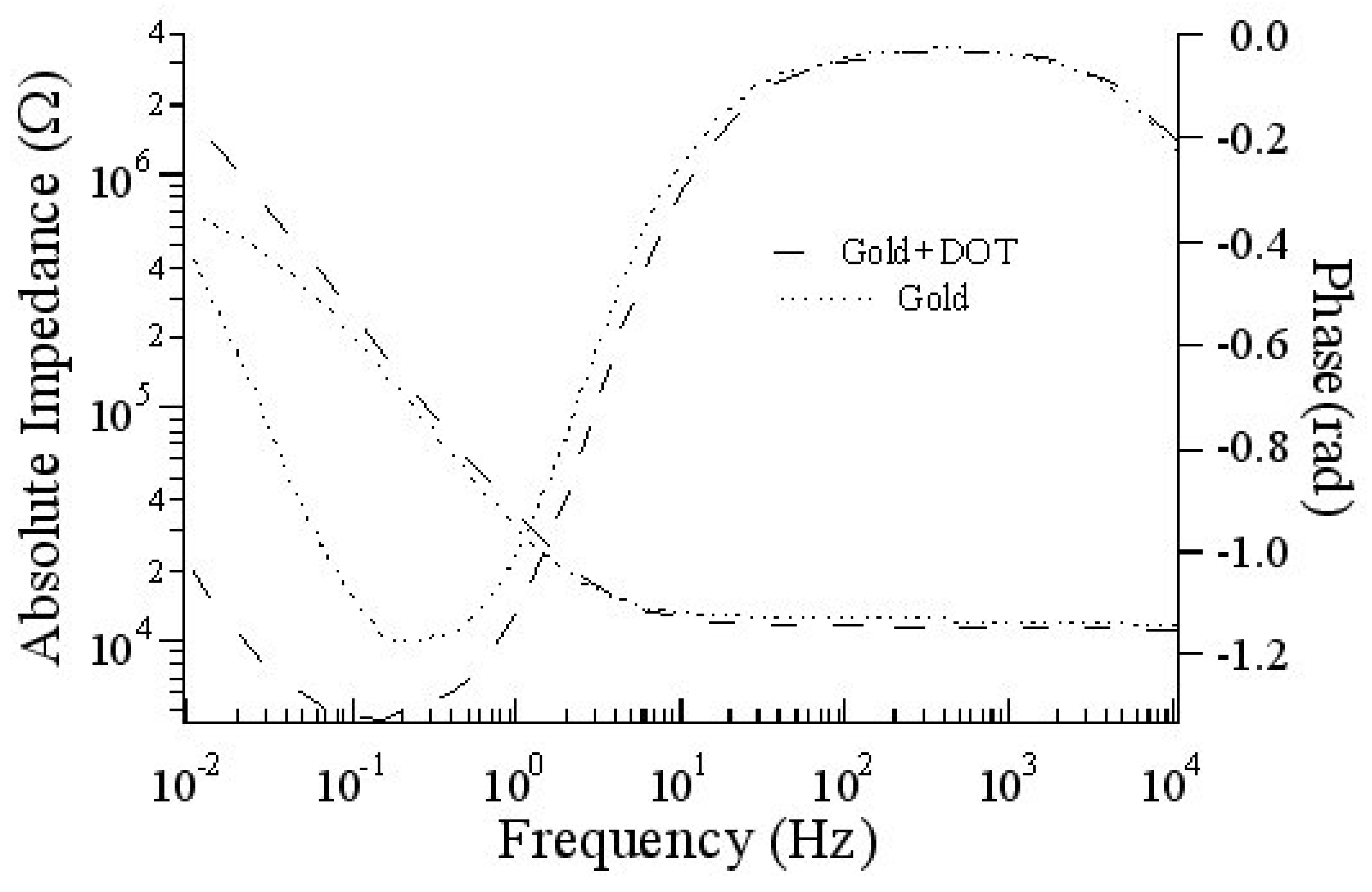
Impedance spectrum of gold/elecrolyte and gold/DOT/electrolyte interface between 10-2 and 1×10⁵ Hz, at a potential of 0V.
Figure 1a.
Impedance spectrum of gold/elecrolyte and gold/DOT/electrolyte interface between 10-2 and 1×10⁵ Hz, at a potential of 0V.

Figure 1b.
Equivalent circuit which is composed with the capacitance Cdl which is the double layer capacitance , the charge transfer resistance Rct in low frequency regime and a resistance in the high frequency regime, which is the resistance of the electrolyte and all the connexion.
Figure 1b.
Equivalent circuit which is composed with the capacitance Cdl which is the double layer capacitance , the charge transfer resistance Rct in low frequency regime and a resistance in the high frequency regime, which is the resistance of the electrolyte and all the connexion.
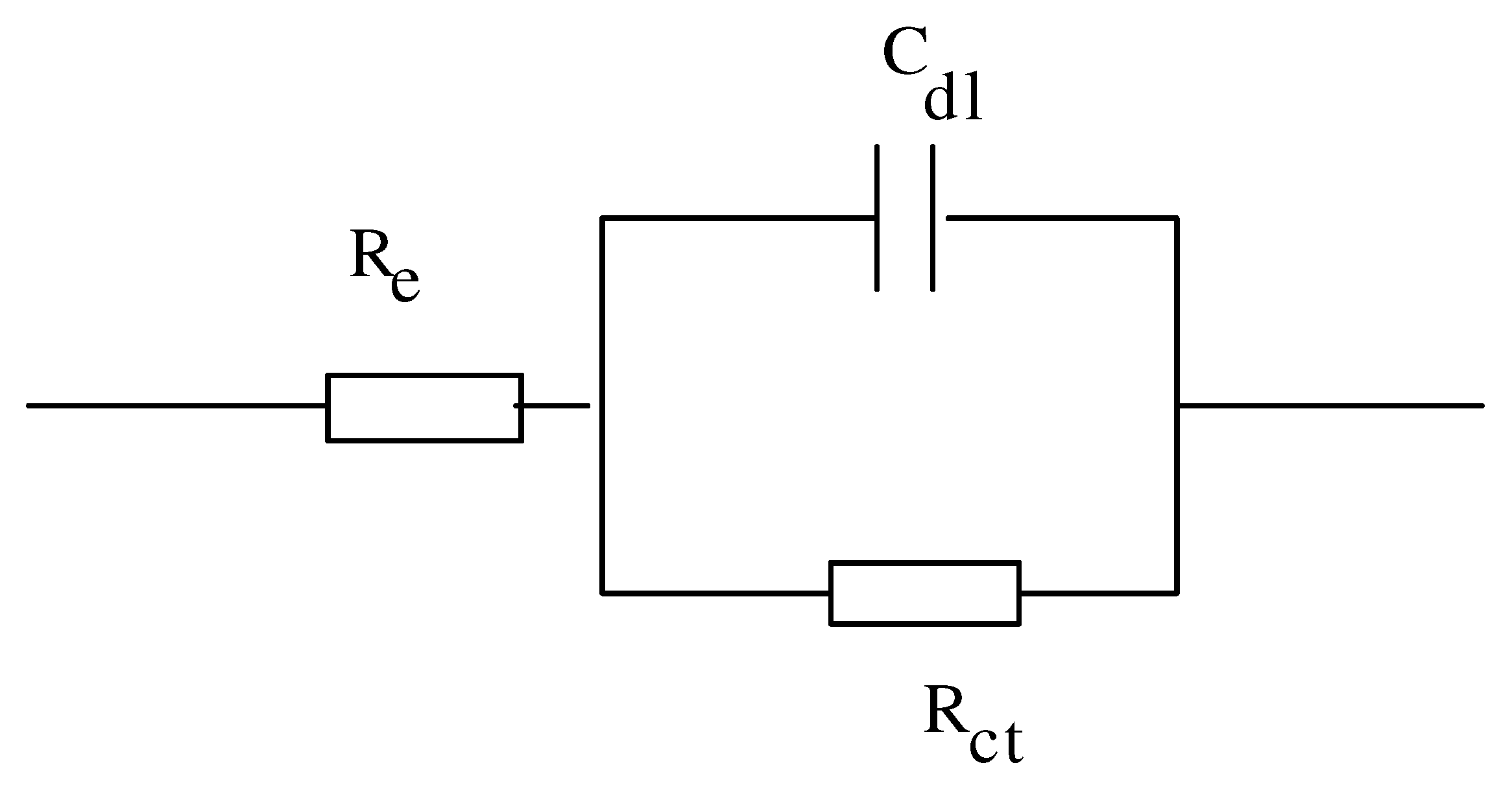
Figure 1c.
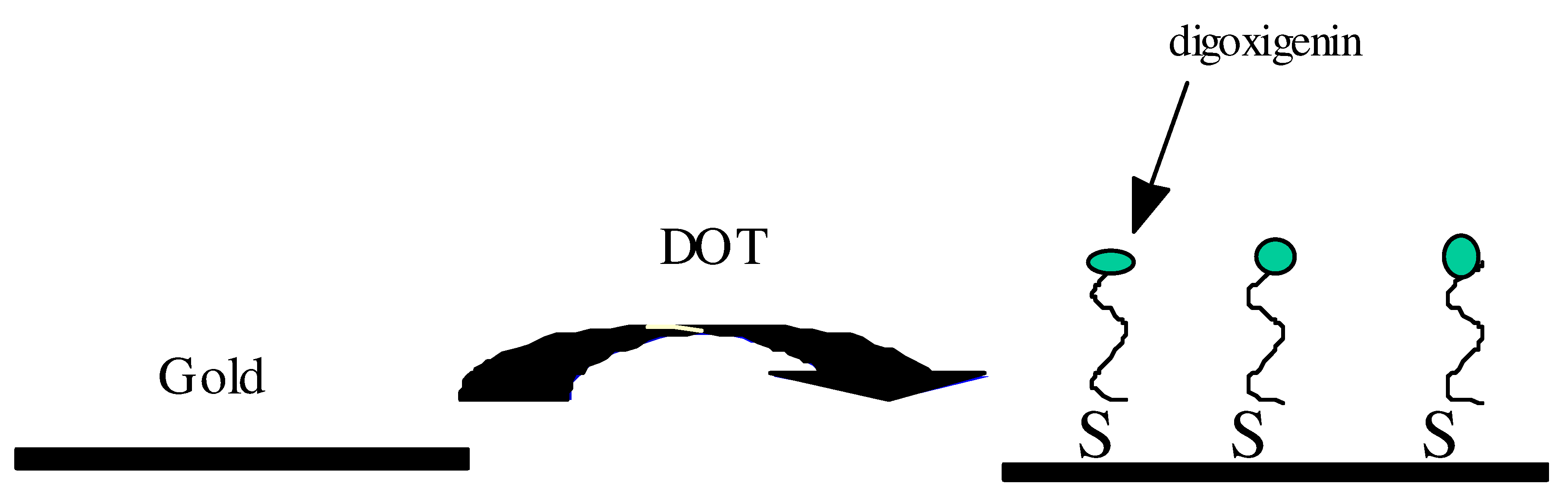
Self Assembly digoxigenin-thiol-labeled ssDNA probe.

Figure 1a shows the impedance spectrum of gold/electrolyte and gold/DOT/electrolyte interface between 10-2 and 1×10⁵ Hz, at a potential of 0V. The impedance spectra are interpreted in terms of equivalent circuit shown in Figure 1b, in which the capacitance Cdl is the double layer capacitance which is dominated by the space charge capacitance of the metal CSC (region of band bending) and the charge transfer resistance Rct in low frequency regime. The resistance in the high frequency regime, is the resistance of the electrolyte and all the connexion. A capacitance of 5,3.10-6 F/cm2 and a resistance of 6.1x10⁵□Cm2 has been obtained with the fitting program for the gold/electrolyte interface. The impedance spectra of the gold/DOT/electrolyte interface can be fitted with the same model. The deposition of the self assembled monolayers (DOT) led to a significant increase in the charge transfer resistance and a decrease in the space charge capacitance of the metal. A capacitance of 4,93. 10-6F/cm2 and a resistance of 2.56.106 □Cm2.has been obtained with the fitting program. The capacitance C (4,93.10-6F/cm2) is composed of the space charge capacitance of the metal CSC (region of band bending) in serial combination with the capacitance of the DOT layer. Figure 1c shows the self assembly digoxigenin-thiol-labeled layer on gold.
Specific interaction
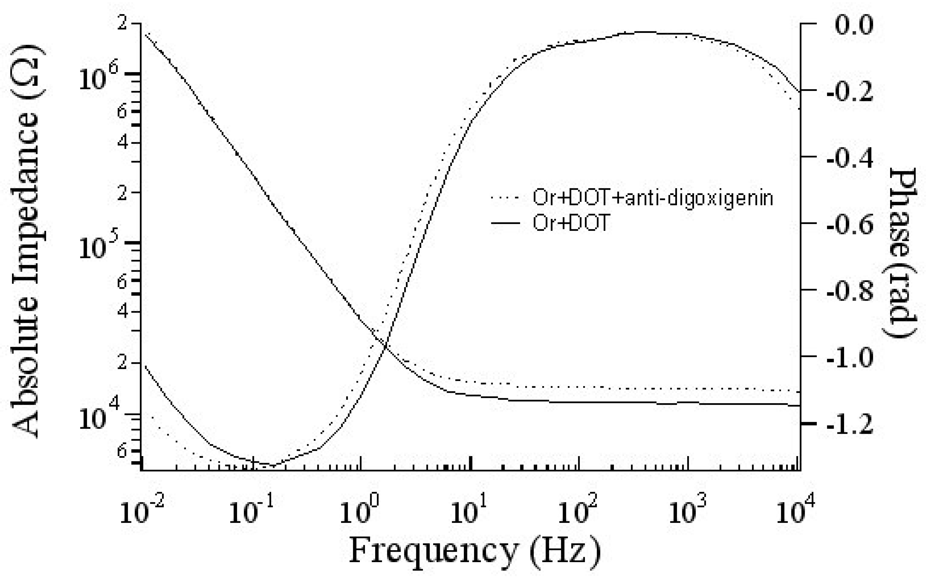
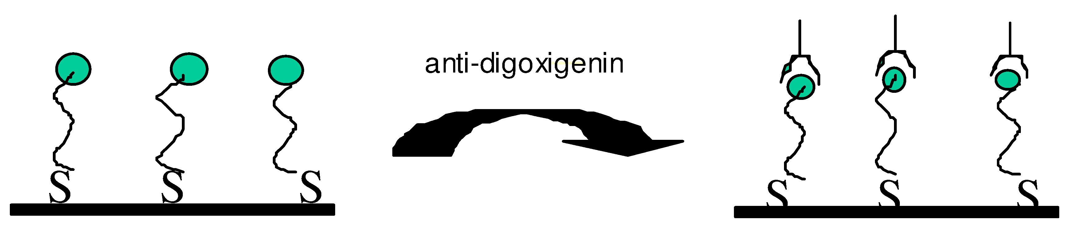
In ordre to see the effect of the specific interaction between the digoxigenin and anti-digoxigenin , the anti-digoxigenin was injected. Figure 2a shows the impedance spectra of the gold electrode with the DOT layers and with anti-digoxigenin. We can see in the phase curve at low frequency regime, the adsorption of anti-digoxigenin include an increase in the charge transfer resistance. Moreover, we can observe a variation in the capacitance. A capacitance of 5.10-6 F/cm2 and a resistance of 4.106□Cm2.has been obtained with the fitting program. This increase of the capacitance is due to the charge interaction between the two biomolecules. The adsorption of the anti-digoxigenin not behave like a independant dielectric medium (Figure 2b).
Hybridization
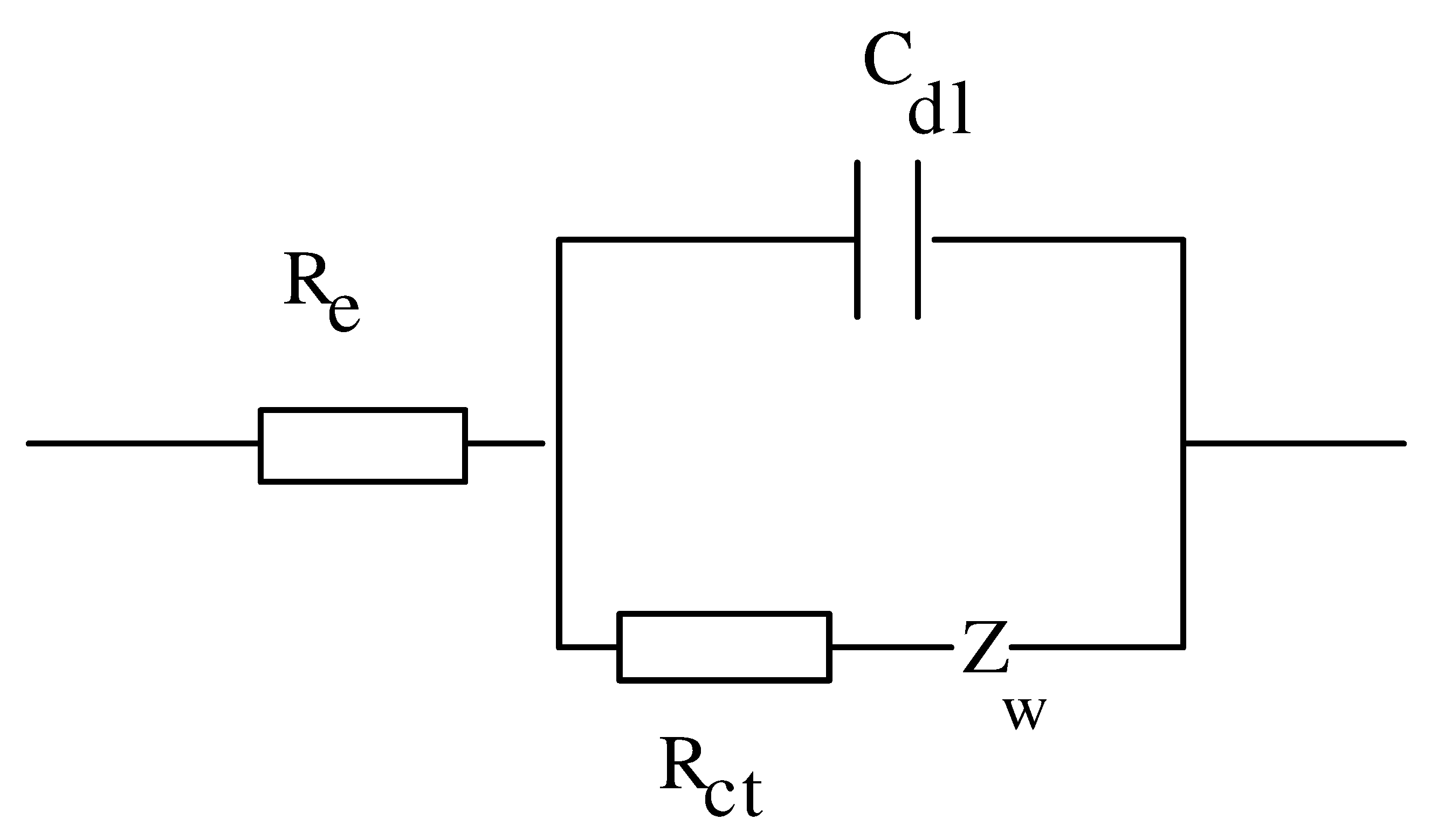
We expose the gold sample with the immobilised DOT to the complementary-biotin 19-mer DNA. Figure 3a shows impedance spectra of the DNA hybridization. The impedance spectra of the gold electrode with DOT layer can be fitted with electric model in Figure 1b. After the hybridization, the impedance spectra has been changed. The impedance spectra has to be fitted with another electric model shown in Figure 3b. These results strongly suggest that the interpretation of the DNA layer as an ideal, dielectric layer ( represented by a parallel connection of a resistance and a capacitance) is not valid. The deviation from the theoretical value for a capacitance (□=1), strongly indicates that the DNA layer behaves like a diffusion element, where the theoretically predicted frequency exponent is 0.5. In this approach, the DNA layer is represented by Randles circuit which a phase transfer resistance Rct, an interface capacitance, Cdl, and a Warburg element ZW are introduced. The last element describes the diffusion normal to the electrode surface through the layer. We obtain a value of 0.67 for
the experimental frequency exponent, and 1.3x10⁵ □cm2 for the Warburg impedance with the fitting program.
Conclusion
Impedance spectroscopy is a powerful technique which has been extensively used for protein affinity binding in the past decades. In this work, ue use impedance spectroscopy technique for DNA hybridization. The interaction between the two DNA strands has been studied after we measure the specific interaction between the digoxigenin and the anti-digoxigenin labeled.
Acknowledgements
The author (Dr.A.Abdelghani) thanks the Alexander Von Humboldt Foundation for the material donation.
References
- Muratsugu, M.; Ohta, F.; Miya, Y.; Hosokawa, T.; Hosokawa, S.; Kamo, N.; Ikeda, H. J. Anal. Chem. 1993, 65, 2933–2937. [CrossRef] [PubMed]
- Streeghorn, C.; Skladalt, P. J. Biosensors &Bioelectronics 1997, 12, 19–27.
- Ketterer, T.; Stadler, H.; Rickert, J.; Bayer, E.; Gopel, W. J. Sensors and Actuators B 2000, 65, 73–75. [CrossRef]
- Okahata, Y.; Kawas, M.; Niikura, K.; Ohtake, F.; Furusawa, H.; Ebara, Y. J. Anal. Chem. 1998, 70, 1288–1296. [Google Scholar] [CrossRef] [PubMed]
- Caruso, F.; Rodda, E.; Neil Furlong, D. J. Anal. Chem. 1997, 69, 2043–2049. [Google Scholar] [CrossRef] [PubMed]
- Zhou, X.C.; Huang, L.Q.; Fong, S.; Li, Y. J. Biosensors &Bioelectronics. 2001, 16, 85–95. [Google Scholar]
- Okahata, Y.; Matsunobu, Y.; Ijiro, K.; Mukae, M.; Amurakami; Makino, K. J. Am. Chem. Soc. 1992, 114, 8299–8300. [Google Scholar] [CrossRef]
- George, G. Guilbault and Bertol Hock Anal. Letters. 1995, 28, 749–764. [Google Scholar]
- Marie, R.; Jensenius, H.; Thaysen, J.; Christensen, C.B.; Boisen, A. Ultramicroscopy. 2002, 91, 29–36. [Google Scholar]
- Koblinger, C.; Drost, S.; Aberl, F.; Wolf, H.; Koch, S.; Woias, P. J. J. Biosensors &Bioelectronics. 1991, 7, 397–404. [Google Scholar]
- Zilberman, G.; Tsionsky, V.; Gileadi, E. Electrochimica Acta. 2000, 45, 3473–3482. [Google Scholar]
- MacDonald, J.R. Impedance spectroscopy; John Wiley & Sons: New York, 1987. [Google Scholar]
- Hillebrandt, H.; Wiegand, G.; Sackmann, E. Langmuir. 1999; 15, 8451–8459. [Google Scholar]
- Wiegand, G. Fundamental principles of the electric properties of supported lipid membranes investigated by advanced methods of impedance spectroscopy. Ph.D. thesis, Shaker verlag, Technishe Universitat of Muenchen, Germany, 1999. [Google Scholar]
- Hillebrandt, H.; Abdelghani, A.; Abdelghani-Jacquin, C.; Aepfelbacher, M.; Sackmann, E. Appl Phys A. 2001, 73, 5, 539–546. [Google Scholar]
Figure 2a.
Impedance spectra of the gold electrode with the DOT layers and with anti-digoxigenin.

Figure 2b.
Specific interaction between the digoxigenin and anti-digoxigenin.

Figure 3a.
Impedance spectra of the DNA hybridization.
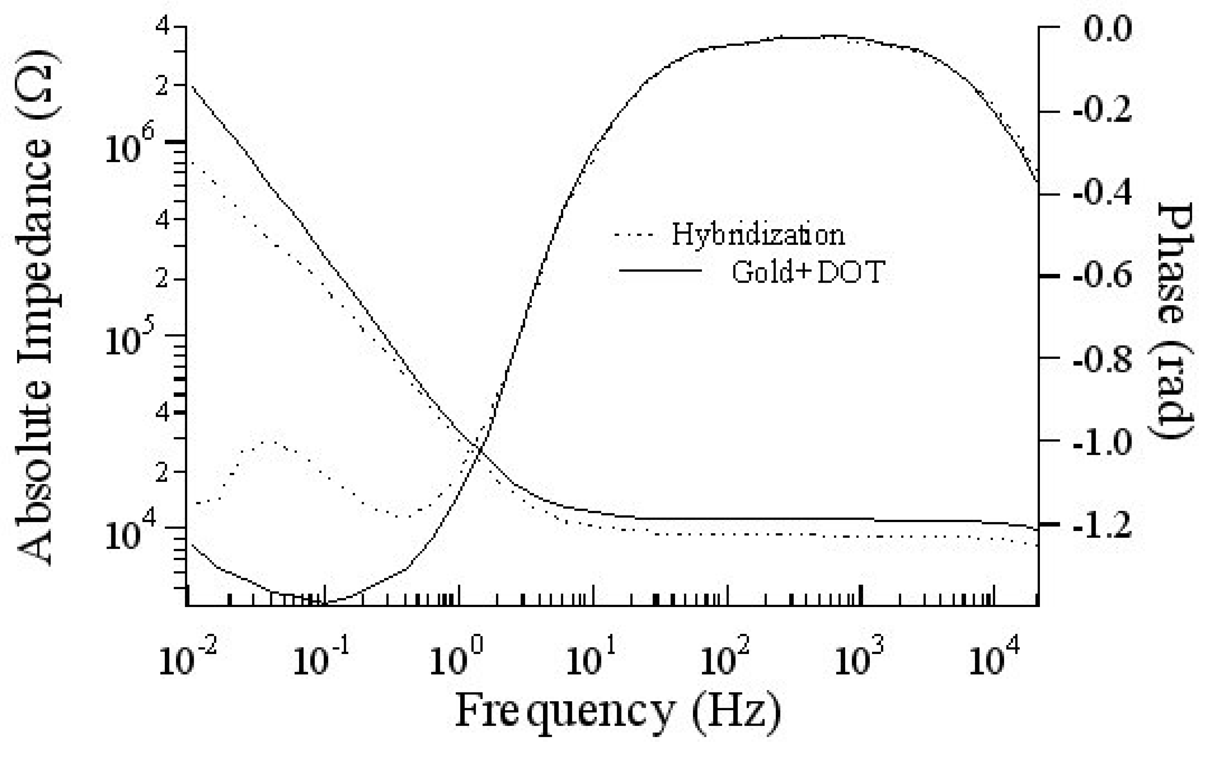
Figure 3b.
Electric model used for the DNA hybridization.
Sample Availability: Available from the authors. |
© 2003 by MDPI (http://www.mdpi.org). Reproduction is permitted for noncommercial purposes.
Share and Cite
MDPI and ACS Style
Hleli, S.; Abdelghani, A.; Tlili, A. Impedance Spectroscopy Technique for DNA Hybridization. Sensors 2003, 3, 472-479. https://doi.org/10.3390/s31000472
AMA Style
Hleli S, Abdelghani A, Tlili A. Impedance Spectroscopy Technique for DNA Hybridization. Sensors. 2003; 3(10):472-479. https://doi.org/10.3390/s31000472
Chicago/Turabian StyleHleli, S., A. Abdelghani, and A. Tlili. 2003. "Impedance Spectroscopy Technique for DNA Hybridization" Sensors 3, no. 10: 472-479. https://doi.org/10.3390/s31000472