Mediated Electron Transfer at Redox Active Monolayers. Part 4: Kinetics of Redox Enzymes Coupled With Electron Mediators

Physical Electrochemistry Laboratory, Department of Chemistry, Nasr Institute of Advanced Materials Science, University of Dublin, Trinity College, Dublin 2, Ireland
Sensors 2003, 3(2), 19-42; https://doi.org/10.3390/s30200019
Submission received: 20 December 2002
/
Accepted: 6 January 2003
/
Published: 26 January 2003
Abstract
:A detailed kinetic analysis of the pertinent physical processes underlying the operation of enzyme electrodes immobilized within alkane thiol self assembled monolayers is developed. These electrodes utilize a soluble mediator, which partitions into the monolayer, regenerates the active catalytic form of the enzyme and is re-oxidized at the underlying support electrode surface giving rise to a current which reflects kinetic events at the enzyme surface. Both the enzyme/substrate and enzyme mediator kinetics have been quantified fully in terms of a ping-pong mechanism for the former and Michaelis-Menten kinetics for the latter. The effect of substrate and mediator diffusion in solution have also been specifically considered and the latter processes have been shown to result in a complex expression for the reaction flux. Four limiting kinetic cases have been enumerated and simple expressions for the reaction flux in each of these rate limiting situations have been developed. Kinetic case diagrams have been presented as an aid to mechanistic diagnosis. The complicating effects of diffusive loss of reduced mediator from the enzyme layer have also been examined and the relation between the observed flux corresponding to reduced mediator oxidation at the support electrode and the substrate reaction flux in the enzyme layer have been quantified in terms of an efficiency factor. Results extracted from recently published practical realizations of immobilized monolayer enzyme systems have been discussed in the context of the proposed model analysis.
Introduction
The chemistry of molecularly designed electrode surfaces has been a major aspect of interfacial electrochemistry for over twenty years. ‘Tailormade’ electrode surfaces at the molecular level provide much added value to the unique feature inherent in electrochemistry where, as recently stated by Murray [1], ‘…one can employ the electrode potential as a source or sink of pure, uncomplicated electrons of flexibly chosen free energy…’. This feature of electrochemistry is readily apparent when the reaction is Nernstian or reversible. However many redox reactions of practical importance are irreversible. They exhibit finite kinetics at the electrode surface, an activation energy barrier at the interface must be overcome, significant overpotential must be applied to make the reaction proceed at a finite rate, and the rate of product formation, and indeed its identity, will depend in a marked manner on the nature of the electrode surface. Hence the quest to understand and control electrochemical reaction kinetics and catalysis has been the motivation of research in physical electrochemistry for decades.
The concept of surface modification has been utilized extensively in the area of bioelectronics which is a rapidly growing field at the junction of chemistry, biochemistry and physics. A biosensor device combines the exquisite selectivity of biology with the processing power of modern microelectronics to offer powerful new analytical tools with major applications in medicine, environmental diagnostics and in the food and processing industries. Biosensors consist of a biological receptor microstructure in which there is a specific molecular interaction between the receptor and the target analyte species (the substrate) . This receptor structure is coupled to an electronic transducer which converts the chemical/biochemical activity into electrical signals which can be amplified, stored, displayed and manipulated.
In the present paper we focus attention on biosensor systems which utilize redox enzymes such as the flavoprotein glucose oxidase (β-D-glucose:oxygen 1-oxido-reductase, EC 1.1.3.4) which is immobilized within an alkane thiol monolayer deposited on the surface of a support electrode. This type of biosensor system will use electrochemical transduction via the amperometric detection of a suitable redox active mediator species at the underlying support electrode surface. The immobilization of monolayers of enzymes onto the surface of self assembled monolayers has been the subject of considerable recent interest [2,3]. Indeed in a recent review by Wilner and Katz [4] it is stated that ‘integration of redox enzymes with an electrode support and formation of an electrical contact between the biocatalyst and the electrode is the fundamental subject of bioelectronics and optobioelectronics’.
In this paper we develop a simple kinetic model to describe the operation of an amperometric enzyme electrode in which the enzyme is immobilized within a self assembled monolayer and in which electronic communication between the enzyme and the electrode is effected by a mobile electronic relay mediator species . This analysis will build on previous work reported by Bourdillon and co-workers [5], Tatsuma and Watanabe [6], Bartlett, Tebbutt and Tyrrell [7], and most recently by Goodring et al [3c].
Some General Comments Regarding the Development of a Model for Amperometric Enzyme Electrodes Utilizing Immobilized Enzymes
There has been considerable interest in recent years in the immobilization of enzymes within electronically conducting and redox conducting polymer films. Electrochemical polymerization provides a simple and attractive approach for the immobilization of enzymes at electrode surfaces. The process can be controlled by the choice of electrode potential and will therefore allow accurate control of the polymer film thickness and hence the amount of enzyme entrapped in close proximity to the electrode surface. Progress in this area has been outlined in the recent reviews of Bartlett and Cooper [8], and Chaubrey and co-workers [9,10]. The kinetics of immobilized enzymes dispersed in polymer films of appreciable thickness has been reported by Bartlett and Whittaker [11], Marchesiello and Genies [12] Bartlett and Pratt [13] and Karube and co-workers [14]. The kinetic analysis of a dispersed enzyme configuration within a porous polymer layer is complex. Typical processes to be modeled are outlined schematically in figure 1.
The scheme is based on a redox enzyme such as glucose oxidase which follows a ‘ping-pong’ reaction mechanism. In the figure A/B represents the mediator redox couple, Eox and Ered, and S/P represent the substrate and product species respectively. We assume that the enzyme E is immobilized within the polymer matrix such that its concentration is uniform throughout the thickness L of the polymer layer. The substrate is free to diffuse through the film with a diffusion coefficient DS. It should be noted that the value of the substrate diffusion coefficient for transport within the porous matrix may differ in magnitude from that exhibited by the substrate in solution. Partitioning of the substrate across the membrane/solution interface occurs and is quantified by a partition coefficient κS. Bartlett and Pratt [13] have noted that the redox mediator may be entrapped within the enzyme layer or it may be present in both the enzyme layer and in bulk solution. Both situations are found in practice. Bartlett and Pratt [13] have considered the former situation in which the mediator is trapped within the film. In the present paper we consider the latter scenario where the mediator is free in solution in its oxidized form and can diffuse into the enzyme layer with a diffusion coefficient DA and a partition coefficient κA. A typical example of the latter situation is the use of oxygen as mediating species. Cases also arise when the solution phase mediator is in its reduced form such as is the case for a substituted ferrocene. We assume that the mediator can only be regenerated at the electrode surface giving rise to a current which can be used to monitor the catalytic sequence of reactions. The model depected in figure 1 refers to the situation of heterogeneous mediation. This should be distinguished from homogeneous mediation in which the substrate, enzyme and mediator are all located within the diffusion layer adjacent to a support electrode surface. This situation has been recently discussed by Albery and co-workers [15] and by Bartlett and Pratt [16]. We will not examine homogeneous mediation in this paper.
We note from figure 1 that a detailed kinetic analysis of an immobilized enzyme electrode can be complex and daunting. If the immobilization matrix is of a finite thickness then both the bounded diffusion of mediator and substrate within the matrix must be considered in the context of the Fick diffusion equation. Furthermore the reaction kinetics between oxidized enzyme and substrate must be considered. This will be quantified in terms of the Michaelis-Menten reaction scheme [17]. Furthermore the bimolecular reaction kinetics between oxidized mediator and reduced enzyme must be taken into consideration. We also must consider the process of re-oxidation of the reduced mediator at the support electrode surface. This may be kinetically facile and be described by the Nernst equation, or more generally, if it is kinetically sluggish, the Butler-Volmer equation may be utilized. In general non linear reaction/diffusion equations are developed as described by Bartlett and Pratt [13]. In the present paper we simplify the analysis by assuming that the immobilization matrix is thin and so concentration polarization of substrate and mediator within the immobilization matrix may be neglected. This enables us to focus attention on the kinetic processes occurring within the membrane region, and complex non linear reaction/diffusion equations do not have to be solved. We will also specifically consider the influence of concentration polarization of substrate and mediator in the adjacent solution phase region and make use of the Nernst Diffusion layer approximation [18]. We will develop the kinetic model in the context of the steady state approximation and so the analysis will be especially pertinent to rotating disc electrode voltammetry. Our method of analysis and mode of approach to the problem will be similar to that described in previous papers in this series [19,20,21].
A Model for Amperometric Monolayer Immobilized Enzyme Electrodes Utilizing Soluble Mediators
The simplified model which we will adopt in the present paper is schematically presented in figure 2. The redox enzyme is assumed to be located within a thin non conductive layer of thickness L deposited onto the surface of a conducting support electrode. This layer may be an alkane thiol film formed via adsorptive self assembly from solution. We assume that the enzyme is homogeneously distributed in a plane located at x = L, at the interface between the thiol film and the adjacent solution.
We consider the following reaction scheme:
![Sensors 03 00019 i001]()
![Sensors 03 00019 i002]() where the oxidized form of the enzyme Eox reacts with the substrate S to form (via an enzyme/substrate complex as intermediate) product P and reduced enzyme Ered . The oxidized form of the mediator species A partitions from solution into the enzyme layer and reacts with the reduced enzyme to regenerate the active oxidized enzyme and produce the reduced form of the mediator B. A subsequently can be electrochemically regenerated at the support electrode via the reaction of B which we assume to occur with kinetic facility.
where the oxidized form of the enzyme Eox reacts with the substrate S to form (via an enzyme/substrate complex as intermediate) product P and reduced enzyme Ered . The oxidized form of the mediator species A partitions from solution into the enzyme layer and reacts with the reduced enzyme to regenerate the active oxidized enzyme and produce the reduced form of the mediator B. A subsequently can be electrochemically regenerated at the support electrode via the reaction of B which we assume to occur with kinetic facility.


Hence the surface concentrations of reduced and oxidized mediator species b0 and a0 are related via the Nernst equation. Of course when measuring the steady state amperometric response of electrodes of this type in practice, it is usual to hold the electrode at a sufficiently oxidizing potential that the mediator is entirely in its oxidized form at the electrode surface. Under such conditions we can set b0=0. In the following analysis this assumption will be made. We will also assume that the substrate S is electrochemically inert and does not react directly at the support electrode surface. It only interacts with the redox enzyme. We assume that the value of the mediator concentration in the bulk solution is a∞ and is present only in its oxidized form. Hence the concentration of the reduced form of the mediator B is zero outside the diffusion layer which is assumed to have a thickness δ.
The observed current i is related to the net flux fΣ corresponding to the reaction of mediator B at the electrode surface via the Faraday relationship, and is given by
where n denotes the number of electrons transferred, F is the Faraday constant and A represents the geometric area of the electrode, and DB denotes the diffusion coefficient of reduced mediator species in the enzyme layer, which will differ from the corresponding diffusion coefficient in the bulk solution.
This experimentally measurable flux fΣ must be related to the substrate reaction flux fS within the enzyme layer. We will correspondingly show, following an argument initially proposed by Bartlett et al [7], that the required relationship between the fluxes is given by:
where we will determine that 1/ 2 ≤ η ≤ 1. The η parameter reflects the fact that the flux of substrate reacting within the film is not necessarily the same as the flux of reduced mediator detected at the electrode. This is because some reduced mediator can diffuse through the thiol layer away from the electrode and be lost into the adjacent solution. We will see that the precise value of η will depend on how effectively species B moves away from the electrode.
Since the immobilization layer is thin we can neglect diffusive depletion of substrate and mediator within the latter, and so we need only consider the Michaelis-Menten kinetics between the oxidised enzyme Eox and the substrate S and the bimolecular kinetics between the oxidised mediator A and the reduced enzyme Ered. Under steady state conditions both of these processes are in balance, and we can write that:
where denote the partition coefficients for substrate and mediator species respectively and aL, sL denote the oxidised mediator and substrate concentrations at the outer edge of the monolayer at x = L. As previously noted L denotes the thickness of the immobilization layer and eox, ered denote the concentrations of the oxidised and reduced forms of the enzyme. Note also that kC and KM represent the catalytic rate constant and Michaelis constant which are significant parameters which define the enzyme kinetics and k denotes the bimolecular rate constant quantifying the kinetics of the reaction between oxidized mediator and reduced enzyme.
We let denote the total enzyme concentration contained within the monolayer. From eqn.4 we can show that
The substrate reaction flux within the enzyme layer is then given by
We now need to relate the substrate and mediator concentrations at the outer edge of the monolayer at x = L to the corresponding quantities in the bulk solution. This is done using the Nernst diffusion layer approximation where we note that
where D’S and D’A denote the diffusion coefficients of substrate and mediator in the solution phase and we have introduced the mass transport rate constants
We can readily show that
where and represent the mass transport controlled fluxes of substrate and oxidized mediator in the solution with and . Now we note from eqn. 9 that if and then we can neglect the concentration polarization of S and A in the solution and we can set and . This approximation is often used in the literature.
If the expressions presented in eqn.9 are substituted into eqn.6 we can, after quite an amount of algebra obtain the following cubic equation in substrate flux:
where we can show that
In a recent paper dealing with monolayer enzyme electrodes fabricated using self assembled monolayers of alkanethiols, Goodring and co-workers [3c] have derived a similar cubic expression for the substrate flux (eqn.7 of reference 3c), and proceed to solve the cubic equation with a negative discriminant to obtain an expression for fS and hence the observed current i. Indeed they fit their experimental batch amperometry curves to the analytical solution of the cubic equation. This analysis procedure of course is valid , but it must be stated that the direct analytical solution of the cubic equation really does not confer any real physical insight into the nature of the system. Instead it is preferable to adopt a different strategy which has been used in our previous papers of this series [19,21].
Substituting eqn.9 into eqn.6 results in the following expression for the substrate reaction flux
![Sensors 03 00019 i003]()

This rather ungainly expression may be simplified further if we invert both sides to obtain:
The latter expression is now physically transparent in that the first term is related to the bimolecular reaction between reduced enzyme and oxidized mediator, the second term relates to the unsaturated kinetics between substrate and oxidized enzyme, and the third term relates to saturated enzyme kinetics involving decomposition of the enzyme/substrate complex to form product and reduced enzyme. The first two terms on the rhs of eqn.13 are modified by transport factors involving substrate and mediator diffusion in the solution. For instance if the substrate reaction flux in the layer becomes close to the limit imposed by either substrate transport in the solution or mediator transport in the solution then both the substrate reaction rate and the mediator reaction rate will be diminished by the transport terms or The effective concentration of substrate and mediator at the layer/solution interface will be considerably less than their bulk values s∞ and a∞.
We note from eqn.13 that the substrate reaction flux may be limited by three possible processes: bimolecular kinetics between oxidized mediator and reduced enzyme, unsaturated kinetics between oxidized enzyme and substrate, or saturated enzyme kinetics involving decomposition of ES intermediate.
In the analysis so far we have implicitly assumed that the reaction between the oxidized mediator A and the reduced enzyme Ered can be described in terms of a simple bimolecular expression. Karube and co-workers [22] have stated that this assumption may not necessarily be valid. It is possible that the mediator/enzyme reaction may also be described in terms of Michaelis-Menten kinetics. In such a situation the mediator may bind to the enzyme and form a complex which will subsequently decompose. In this case eqn.4 must be replaced by:
where denotes the Michaelis constant for the mediator species. We note that when the mediator concentration in the layer is smaller than the Michaelis constant , then the expression outlined in eqn.14 reduces to that previously presented in eqn.4, but in this case the bimolecular rate constant takes the form . For the more complicated situation in which the mediator/enzyme reaction exhibits Michaelis Menten kinetics, we can repeat the analysis just described and show that the inverse substrate reaction flux is now given by:
![Sensors 03 00019 i004]()

The first term on the rhs of eqn.15 corresponds to rate determining unsaturated mediator/enzyme kinetics modified by a mediator transport term. The unsaturated rate constant is given by . The second term corresponds to rate determining unsaturated enzyme/substrate kinetics, with a rate constant . The third term corresponds to saturated enzyme kinetics involving rate determining decomposition of the enzyme/substrate complex, and the fourth and final term corresponds to the saturated kinetics involving decomposition of the mediator/enzyme complex. It is clear that the development of a general expression for the inverse substrate flux provides much more information pertaining to the reaction mechanism than solving the cubic equation.
Analysis of the Reaction Kinetics in Terms of Normalized Variables and Kinetic Case Diagrams.
We now follow the procedure adopted in our previous papers and develop a kinetic case diagram for an immobilized enzyme monolayer electrode system. In this analysis we neglect concentration polarization of mediator and substrate in solution. We will assume that both the mediator/enzyme reaction and the substrate/enzyme reaction are described by Michaelis-Menten kinetics. Under such circumstances the reaction flux is given by:
![Sensors 03 00019 i005]()

We now introduce a normalized substrate flux given by:
where denotes the maximum enzyme turnover rate. We also introduce saturation parameters α and β for substrate and mediator as follows:
We finally introduce a kinetic competition parameter γ as:
![Sensors 03 00019 i006]()

Hence γ compares the mediator/enzyme reaction flux to the substrate/enzyme reaction flux. When γ << 1 then fME << fSE and the net flux is limited by the kinetics of the bimolecular reaction between mediator and enzyme. In contrast when γ >> 1 then fME >> fSE and the net flux is limited by the kinetics of the reaction between substrate and enzyme. The substrate saturation parameter α compares the value of the substrate concentration in the layer κSs∞ to the Michaelis constant KM for substrate. When α << 1 then κSs∞ << KM and we have unsaturated enzyme kinetics. In contrast when α >> 1 then κSs∞ >> KM and saturated enzyme kinetics pertain. The mediator saturation parameter β compares the oxidized mediator concentration within the layer, κAa∞, to the Michaelis constant for the mediator K’M. When β << 1 , κAa∞ << K’M, and unsaturated mediator kinetics pertain. This is the situation usually considered in the literature. On the other hand when the mediator concentration within the layer is large, then κAa∞ >> K’M, saturated mediator kinetics will apply and β >> 1.
If eqn. 17, eqn.18 and eqn.19 are substituted into eqn.16 one obtains the following expression for the normalized substrate flux in the layer:
This normalized expression is the most general and is valid for all mediator and substrate concentrations. We can now simply the analysis and assume firstly that the concentration of mediator within the film is low. Under these conditions β << 1 and eqn.20 reduces to:
We now can simplify the latter expression further depending on the value of the substrate saturation parameter α . When the substrate concentration in the layer is small then α << 1 and eqn.21 reduces to:
This expression is valid for the situation where the mediator and enzyme kinetics are unsaturated. We can simplify still further by examining suitable limiting values of the competition parameter γ. Firstly when γ << 1 we recall that the substrate reaction flux is limited by reaction between oxidized mediator and reduced enzyme. Here the normalized flux is given by:
We label this case IA. Transforming into an expression for the flux we get:
Hence when the reaction between oxidized mediator and reduced enzyme is rate determining the flux in the film should exhibit a first order dependence on the bulk concentration of oxidized mediator, provided that the concentration of mediator is not too large. The flux should also be independent of the bulk substrate concentration and exhibit a first order dependence both on enzyme loading and layer thickness. Secondly, when γ >> 1 the substrate reaction flux in the layer will be limited by the unsaturated reaction kinetics between oxidized enzyme and substrate. In this case the normalized flux takes the form:
We label this situation case IB. Re-transforming into the usual variables we get
Hence we note that the reaction flux should be first order with respect to bulk substrate concentration, independent of mediator concentration and first order with respect to enzyme loading and layer thickness. Hence case IA and IB pertain when α << 1 and when β << 1.
We now turn to the situation where α >> 1 and β << 1 . Re-examination of eqn.21 indicates that the approximate expression for the normalized flux is now given by:
Again we get two limiting cases depending on the value of the product αγ. Firstly when αγ << 1 eqn.27 reduces to
which was obtained previously, and case IA is obtained again. Secondly, when αγ >> 1 eqn.27 reduces to:
We label this case II. Here the reaction flux is given by:
and corresponds to rate determining saturated enzyme kinetics. Here the flux will be independent both of bulk substrate and mediator concentrations but will depend linearly on enzyme loading and layer thickness.
We have identified three cases (IA, IB and II) when the mediator concentration in the layer is low. We now turn to the situation when the opposite pertains. In this case eqn.20 reduces to
Again we can simplify by taking the small α and large α limits. Firstly, when α << 1 we get
We now compare the magnitudes of the normalized parameters γ and β. When γ << β eqn.31 reduces to
We label this situation case III. Transforming to the usual expression for the flux we obtain
Hence case III corresponds to the case of saturated mediator kinetics in which the decomposition of the mediator/enzyme complex to form reduced mediator and oxidized enzyme is rate determining. Here the flux is independent of bulk mediator concentration and bulk substrate concentration , but depends in a first order manner on enzyme concentration and layer thickness. On the other hand when γ >> β we get
which again is case IB. Hence case IB pertains also when β >> 1 and so holds for the entire range of the β parameter. Turning again to eqn.30, which holds for the case where the mediator concentration in the layer is high, and considering the case α >> 1 we obtain
Again we can get two possible limits by comparing the magnitudes of αγ and β . Firstly when αγ << β we again get case III.
Whereas in contrast when αγ >> β we get
which is case II. Hence case III is valid when the mediator saturation factor β is large and is valid for the entire range of bulk substrate concentrations or α values. Its region of validity will be determined by the conditions γ << β and αγ << β . Case II corresponding to saturated enzyme kinetics is valid for the entire range of β values , and for large values of α, and subject to the restraints that αγ > β and αγ > 1. Hence we have identified three cases (IB, II, III) for the situation where the mediator concentration in the layer is high and all reduced enzyme is bound by mediator.’
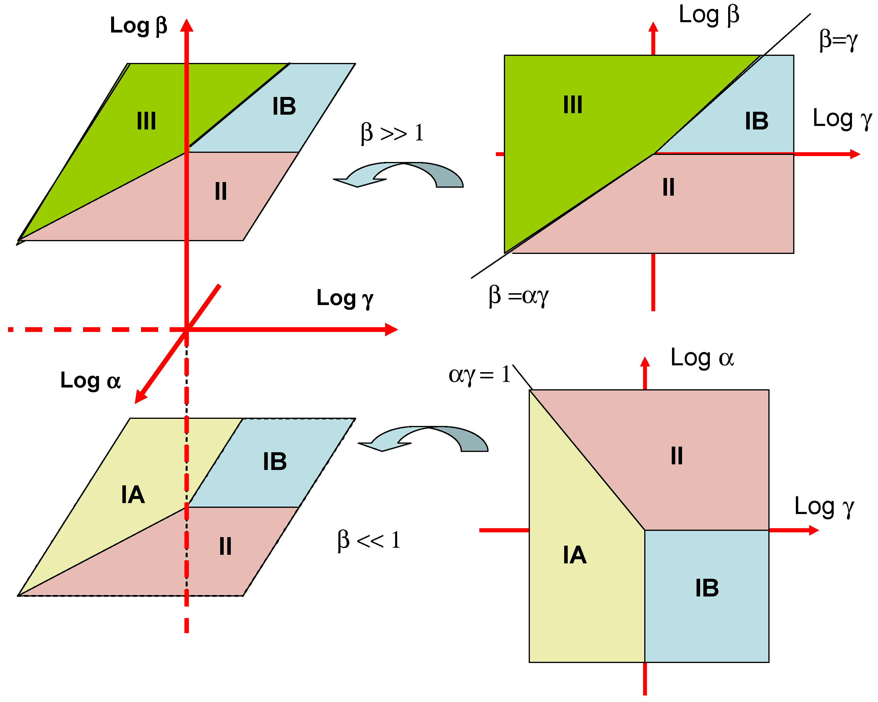
These various mechanistic and kinetic possibilities are presented in terms of a kinetic case diagram in figure 3. The natural axes defining the case diagram are log α, log β and log γ . Although we indicate the general form of the three dimensional case diagram in figure 3 it is more instructive to examine two limiting slices of the diagram. The first is a plot of log α versus log γ valid for β << 1. This is illustrated in the lower right inset in figure 3. We see that case IA is located in a block defined by the line αγ = 1 and γ = 1. Case IB is defined by the quadrant bordered by the lines γ = 1 and α = 1. Finally case II is defined in terms of the region bordered by the lines αγ = 1 and α = 1. Cases IA, IB and II are most often found experimentally since the mediator concentration in the enzyme layer will usually be low. The second slice of the case diagram is presented in the upper right hand inset in figure 3. Here case IB is bounded by the lines β = γ and β = 1. Case II is defined by the lines β = 1 and β = αγ. Finally case III is delineated by the lines β = αγ and β = γ.
We summarize the various kinetic possibilities in table 1 where expressions for the normalized flux, and the substrate flux are outlined for the four cases considered.
In table 2 we outline the reaction orders with respect to bulk mediator concentration, bulk substrate concentration and enzyme surface coverage for each of the rate limiting cases developed in table 1. We note that is is not possible to distinguish between case II and case III by examining the way that the reaction flux varies with enzyme loading, bulk mediator concentration or bulk substrate concentration since an identical set of mechanistic indicators are predicted for both cases.
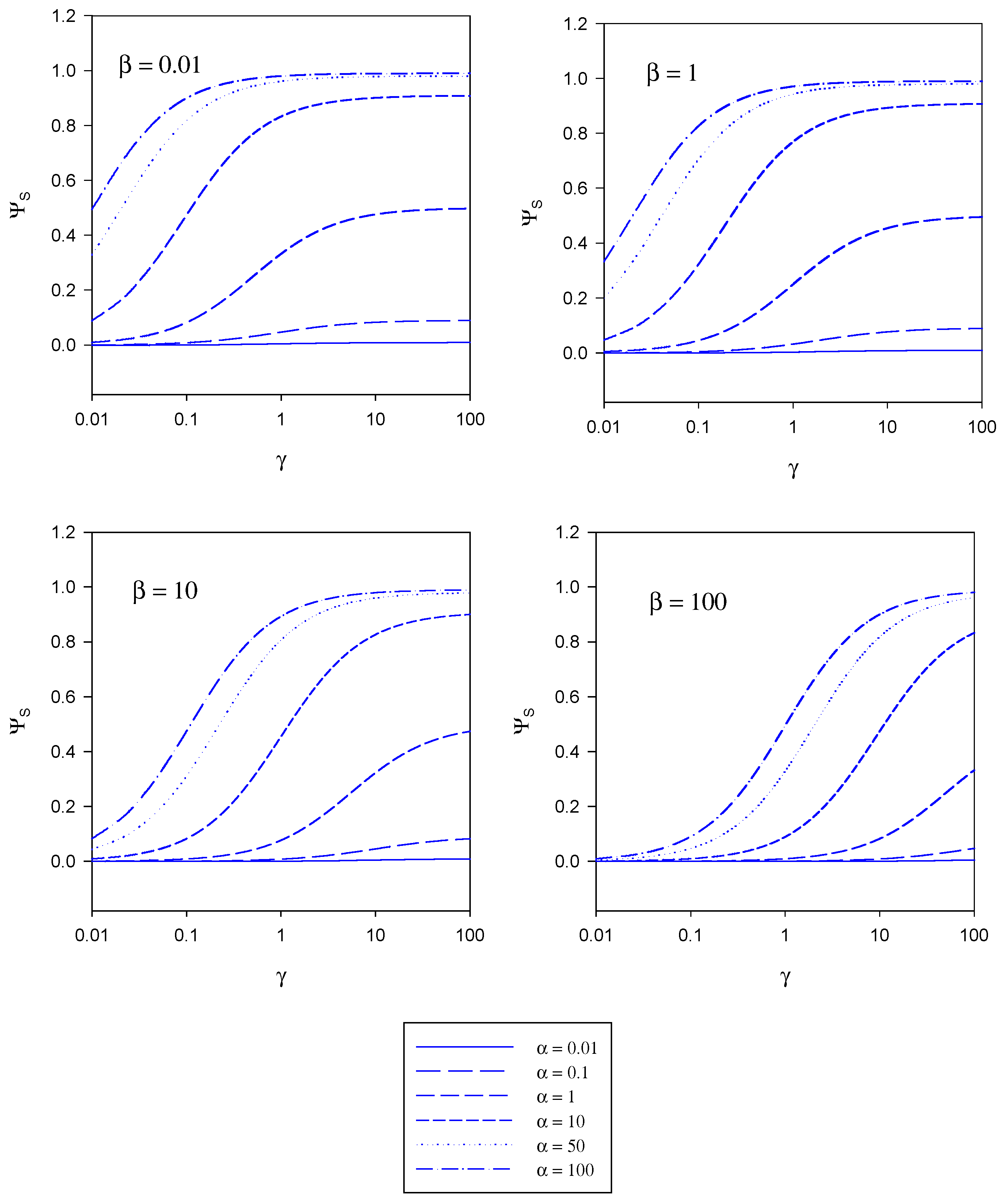
The implications contained in the master equation outlined in eqn. 20 are presented in diagrammatic form in figure 4, figure 5 and figure 6. These curves have been computed using the programme SIGMAPLOT 2000 (Jandel Scientific) .In figure 4 the variation of the normalized substrate flux with the kinetic competition parameter γ is presented in a semi-logarithmic format . The plots are computed for different values of the substrate saturation parmeter α . Each set of curves corresponds to a fixed value of the mediator saturation parameter β. The substrate flux is normalized with respect to the maximum enzyme turnover rate. For a given value of β we note that the normalized substrate flux increases with increasing γ value, and approaches a limiting value as γ increases. The magnitude of the limiting normalized flux increases with increasing α value. We recall that γ compares the mediator/enzyme reaction flux to the substrate/enzyme reaction flux. When γ << 1 then fME << fSE and the net flux is limited by the kinetics of the bimolecular reaction between mediator and enzyme. In contrast when γ >> 1 then fME >> fSE and the net flux is limited by the kinetics of the reaction between substrate and enzyme. A maximum normalized flux of unity is attained when the kinetics are limited by the reaction between substrate and enzyme and when the concentration of substrate within the enzyme layer is much larger than the Michaelis constant (large α values). The latter maximum flux is only attained at larger γ values when the concentration of mediator is high (large β values).
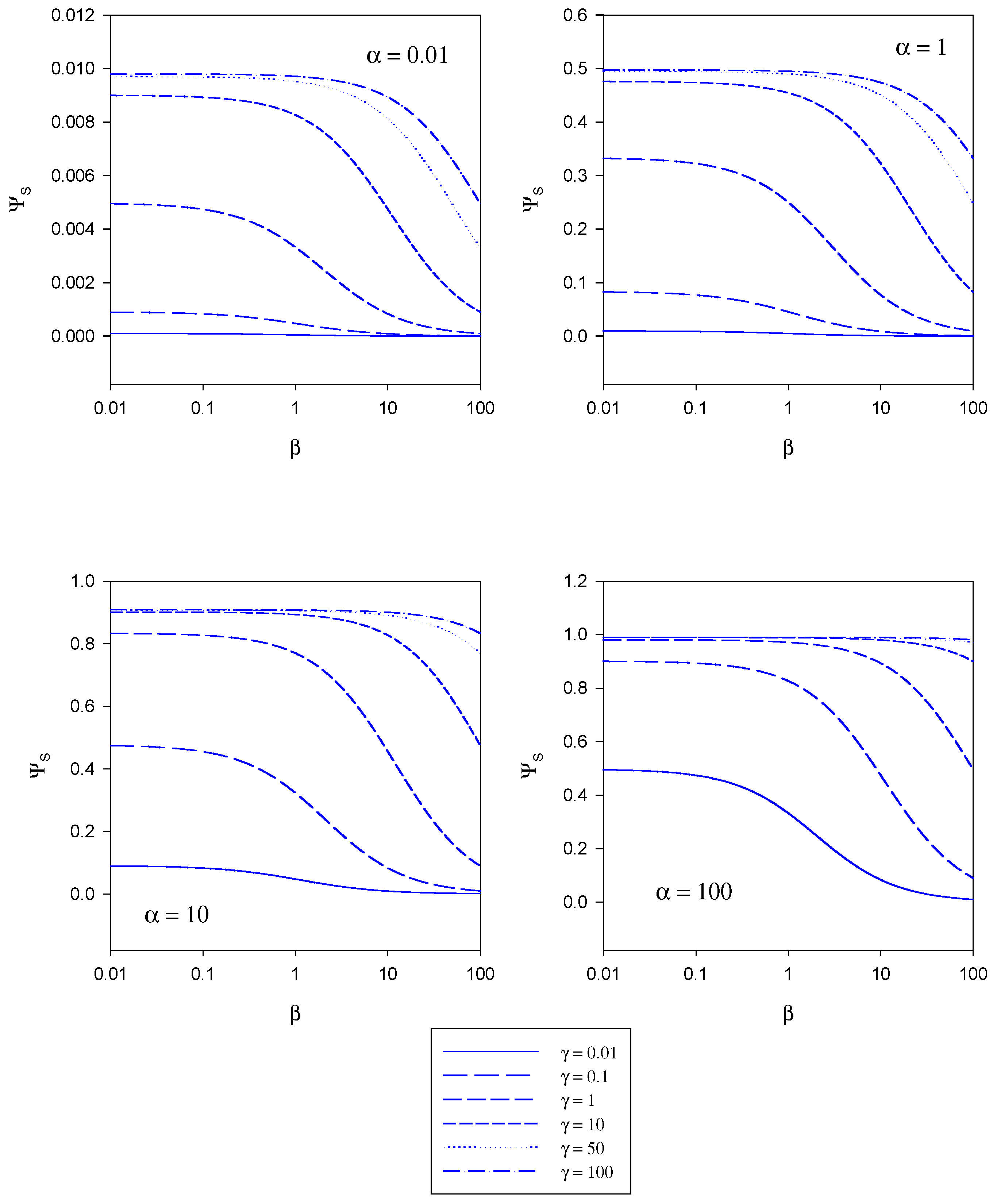
In figure 5 the variation of the normalized substrate flux with the mediator saturation parameter β computed from eqn.20 is presented. The plots are computed for different values of the kinetic competiton parmeter γ which compares the mediator/enzyme reaction flux to the substrate/enzyme reaction flux. Each set of curves corresponds to a fixed value of the substrate saturation parameter α. Here the normalized flux initially set at a constant value the magnitude of which depends on the set value of the substrate saturation parameter α, subsequently decreases with increasing β value. This general trend is observed for all α values examined in the range 0.01 – 100.
In figure 6 the variation of the normalized substrate flux with substrate saturation parameter α is presented. This is the situation most often illustrated in practice and corresponds to a normalized calibration plot or batch amperometry curve. The plots are computed for a range of γ values and for a series of fixed β values. The normalized substrate flux increases with increasing substrate saturation parameter until a maximum value of unity is attained at large values of the latter. This is characteristic of Michaelis-Menten kinetics. This general behaviour is observed independent of the value of the mediator concentration (defined in terms of the parameter β). The dynamic range of the biosensor is also seen to increase when the value of the competition parameter is small although the sensitivity in the latter regime is not very large. The best dynamic range and sensitivity is obtained when the reaction between mediator and enzyme is rate limiting.
Analysis of the Relationship Between the Observed Flux and the Substrate Reaction Flux Within the Immobilized Enzyme Layer
We now derive a relationship between the current flowing across the support electrode/enzyme layer interface and the reaction flux within the layer. We have previously noted that the latter quantities are not identical, since some reduced mediator can diffuse through the enzyme layer away from the electrode and be lost into the adjacent solution. To take this fact into account we have written that . We now will determine an expression for the parameter η following an argument initially proposed by Bartlett [7]. We assume that a rotating disc arrangement is used.
Within the enzyme layer we note that the reduced mediator species B is generated at a uniform rate given by . Furthermore B is lost from the layer via diffusion away from the support electrode towards the outer edge of the enzyme layer. This process is described by the Fick diffusion equation. In the steady state the rate of mediator diffusion and generation must balance and we can write that:
where DB denotes the diffusion coefficient of B in the enzyme layer and b represents the distance dependent concentration of mediator species within the layer of thickness L. We can consider two boundary conditions:
The boundary condition at x = 0 corresponds to the situation at the support electrode/enzyme layer interface. The first statement is that the potential of the electrode is set to a value such that the reduced mediator is immediately oxidized at the support electrode and so its surface concentration is zero. The second statement refers to the fact that the observed flux arises from the oxidation of the reduced mediator at the support electrode surface. The second boundary condition refers to the interface between the enzyme layer and the adjacent solution phase at x = L. Here the reduced mediator concentration has a value bL.
We integrate eqn.29 between 0 and L to obtain:
Noting that eqn.31 reduces to:
The flux of B across the enzyme layer/solution interface is now equated with the flux of B across the diffusion layer in solution and so
where D’B denotes the mediator diffusion coefficient in solution and b*L represents the mediator concentration in the solution phase just outside the enzyme layer, and δ denotes the Nernst diffusion layer thickness. The latter concentration term is related to the mediator concentration at x = L by , where κB denotes the partition coefficient of B. An indefinite integration of eqn.29 from 0 to x results in
A second integration of eqn.34 results in
Noting that b0 = 0 and when x = L, b = bL we obtain that
From eqn.33 we can readily show that
Substituting eqn.36 into eqn.37 we get
We now introduce a flux ratio Φ given by
This quantity relates the diffusive flux of mediator in the diffusion layer to the corresponding diffusive flux of mediator within the enzyme layer. Hence eqn.38 transforms to
This expression can be readily rearranged to generate a relationship between the flux measured at the support electrode surface and that corresponding to reaction within the enzyme layer as follows:
and so we note that the η function is given specifically by
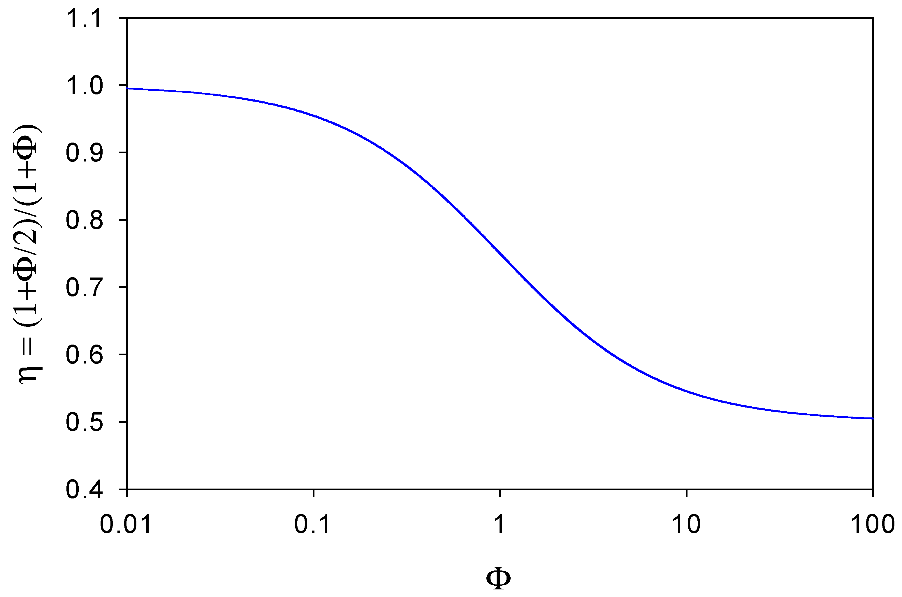
A plot of η versus Φ is outlined in figure 7. When Φ << 1 then η ≅ 1 and the observed flux corresponding to the oxidation of the reduced mediator species at the electrode surface will equal that of the substrate reaction within the enzyme layer. This situation will arise when the diffusive flux f’DB of mediator species through the diffusion layer is much less than the diffusive flux fDB of mediator species through the enzyme layer to the support electrode surface. In these circumstances very little reduced mediator is lost from the film. In contrast, we note from figure 7 that when Φ >> 1 then η → 1/ 2 . Here the reduced mediator species B is lost rapidly from the enzyme layer and diffuses into solution. In figure 7 we see that η has a maximum value of 1 and a minimum value of ½, and η decreases regularly as Φ increases, reflecting the increasing rate of loss of mediator from the layer. Hence we can view the η parameter as an efficiency factor which depends on the ratio of diffusive fluxes of mediator through the enzyme layer and through the solution phase.
We can now write down an expression for the observed steady state current response expected for an immobilized enzyme monolayer electrode. If we neglect concentration polarization effects in the solution then from eqn.16 we note that
![Sensors 03 00019 i007]()

Since this expression contains the diffusion layer thickness δ, then if a rotating disc electrode is used, we would expect that the amperometric response should exhibit a marked rotation speed dependence, because the diffusion layer thickness depends on rotation speed via the Levich relation [23]:
where ν denotes the kinematic viscosity of the solution and ω denotes the angular velocity of the rotating disc electrode. We expect that the amperometric response should decrease with increasing rotation speed and attain a limiting value at high rotation speeds. This behaviour has been observed experimentally by Bartlett and Whitaker for glucose oxidase immobilized in thin poly-pyrrole films using the O2/H2O2 mediator system [11b].
Comparison of model predictions with experimental data
We now refer to the recent paper of Goodring and co-workers [3c] which presents a detailed experimental analysis of an amperometric enzyme electrode consisting of glucose oxidase immobilized within a carboxylic acid terminated alkane thiol self assembled monolayer film . This system used p-benzoquinone as a soluble mediator. Goodring et al [3c] noted that it is advisable to use a short chain alkane thiol since monolayers formed from the latter constituents exhibit less order than monolayer films generated from longer alkane thiol chains. It appears that disordered regions in the monolayer are necessary to enable facile transport of the mobile mediator species through the film to the underlying electrode surface. Films based on 3-mercaptopropionic acid have been shown to exhibit both disordered and ordered domains [24]. Very low enzyme loadings were required in the enzyme electrodes prepared by Goodring and co-workers [3c], typically 0.7 ± 0.3 pmol cm−2, to produce an excellent dynamic range to added glucose. Changes in concentration up to 50 mM glucose can be detected. Analysis of the batch amperometry data provided in the work of Goodring et al [3c] indicated that the Michaelis constant for the substrate was close to 72 mM, which is considerably higher than that reported for glucose oxidase in solution which is 5 mM. This rather large dynamic range for glucose detection can be attributed to either the presence of partition barriers limiting access of substrate to the enzyme or to an enhanced rate of enzyme turnover due to increased mediation efficiency. Goodring and co-workers have estimated that the enzyme layer thickness L is typically 4 x 10⁻⁷ cm whereas the diffusion layer thickness is much larger, typically 10−3 cm. Hence . Hence they propose that the concentration gradient of reduced mediator species within the enzyme layer is much higher than that for reduced mediator diffusion into the adjacent solution. This implies that almost all of the reduced mediator is re-oxidized at the underlying support electrode surface and that since . At the enzyme /solution interface, the concentration of reduced mediator will be low and that of the oxidized form high, and the response of the biosensor will depend on the ability of the enzyme to turn over the substrate. The effect of enzyme loading on the amperometric current response of the biosensor was also examined, and the response as found to be highly sensitive to the amount of enzyme immobilized. A linear relationship between steady state current response and enzyme loading was observed, when the surface coverage of enzyme was varied between 0.019 pmol cm−2 and 0.29 pmol cm−2. The dynamic range of the sensor was not effected by the variation in enzyme loading. The latter observation could be understood in terms of a rate determining enzyme turnover step rather than slow mass transport or enzyme/substrate complex formation . A desirable attribute for a practical biosensor is that the response should be independent of enzyme loading, especially if the activity of the device is to be maintained during storage. Working from the dimensions of the glucose oxidase molecule (308 nm3) the maximum enzyme loading possible for a GOx/SAM system is 4 pmol cm−2 which is considerably less than the loading required for the response to be independent of enzyme loading (ca. 103 pmol cm−2). This therefore is an important limitation for immobilized enzyme monolayer electrodes. Goodring et al [3c] also examined the effect of mediator concentration on the amperometric response of the biosensor. An increase in mediator concentration (the range 0.1 mM to 5 mM was examined) was found to result in both an increase in sensitivity and dynamic range (figure 4, reference 3c). The latter observations were assumed to reflect the fact that the increased concentration of mediator brought about an increased rate of turnover of the reduced enzyme back to its catalytically active oxidized form. Furthermore the extension in dynamic range with increased mediator concentration was rationalized in terms of the proposal that the sensor was limited by the conversion of the reduced enzyme to the oxidized enzyme rather than the reaction of the substrate with the oxidized form of the enzyme, or the dissociation of the enzyme/substrate complex. This corresponds to case IA in our terminology. In the latter situation according to the diagnostic parameters outlined in table 1 the steady state current should be first order in mediator concentration, first order in enzyme concentration and zero order in substrate concentration. From figure 4 in the Goodring paper we note that the batch amperometry profiles indicate only a slight dependence on the current with increasing substrate cocentration and a first order increase in current response with mediator concentration.
Goodring et al [3c] examined the variation in sensor sensitivity with rotation speed, and showed that relative to a quiescent solution, there is a decrease in sensitivity with stirring, however the steady state current level did not subsequently vary very significantly with increasing rotation rate as would be predicted via eqn.43 and eqn.44. Again this implies that diffusion of reduced mediator species B to the underlying support electrode surface is greater than the diffusive loss of reduced mediator to the solution and that the observed steady state current almost fully reflects the kinetic processes occurring at the enzyme surface.
Returning to eqn.15 we note that the inverse flux, when the mediator/enzyme kinetics are unsaturated, is given by
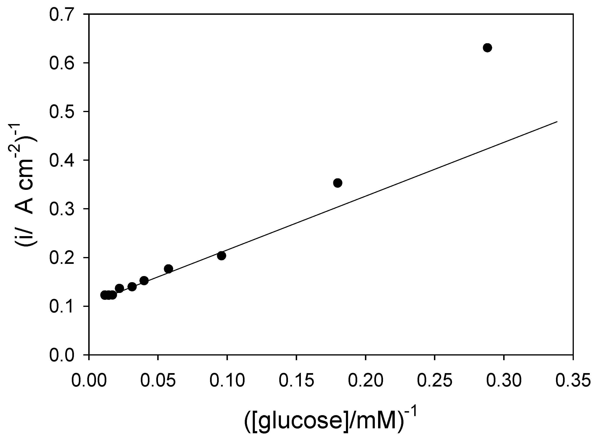
![Sensors 03 00019 i008]() and so a plot of inverse flux versus inverse substrate concentration should be linear provided that the kinetic terms or can be neglected. If the latter terms are significant then the inverse flux versus inverse substrate concentration plot should deviate from linearity. We present an analysis of of the Goodring batch amperometry data (figure.2 reference 3c) in figure 8. This plot is analogous to a Lineweaver-Burk graph used in enzyme kinetics. We note that the plot deviates significantly from linearity at low substrate concentrations. This arises because of mediator or substrate concentration polarization effects in the solution, as predicted from eqn.15.
and so a plot of inverse flux versus inverse substrate concentration should be linear provided that the kinetic terms or can be neglected. If the latter terms are significant then the inverse flux versus inverse substrate concentration plot should deviate from linearity. We present an analysis of of the Goodring batch amperometry data (figure.2 reference 3c) in figure 8. This plot is analogous to a Lineweaver-Burk graph used in enzyme kinetics. We note that the plot deviates significantly from linearity at low substrate concentrations. This arises because of mediator or substrate concentration polarization effects in the solution, as predicted from eqn.15.

Concluding Comments
In the present communication we have presented a detailed theoretical analysis of the pertinent physical processes underlying the operation of enzyme electrodes immobilized within alkane thiol self assembled monolayers. These electrodes utilize a soluble mediator which partitions into the monolayer, regenerates the active catalytic form of the enzyme and is re-oxidized at the underlying support electrode surface giving rise to a current which reflects kinetic events at the enzyme surface. Both the enzyme/substrate and enzyme mediator kinetics have been quantified fully in terms of a ping-pong mechanism for the former and Michaelis-Menten kinetics for the latter. The effect of substrate and mediator diffusion in solution have been specifically considered and the latter processes have been shown to result in a complex expression for the reaction flux. Four limiting kinetic cases have been enumerated and simple expressions for the reaction flux in each of these rate limiting situations have been developed. Kinetic case diagrams have been presented as an aid to mechanistic diagnosis. The complicating effects of diffusive loss of reduced mediator from the enzyme layer have also been examined and the relation between the observed flux corresponding to reduced mediator oxidation at the support electrode and the substrate reaction flux in the enzyme layer have been quantified in terms of an efficiency factor. Results extracted from recently published practical realizations of immobilized monolayer enzyme systems have been discussed in the context of the proposed model analysis.
Acknowledgements
The author is grateful to the Irish National funding bodies (Higher Education Authority and Irish Research Council for Science, Engineering and Technology) for the receipt of funding under the PRTLI (Grant: HEA-PRTLI-IAMS, Cycle 3) and Basic Research Programmes (Grant number SC/02/169).
References and Notes
- Murray, R.M. Introduction to the chemistry of molecularly designed electrode surfaces. Murray, R.M., Ed.; In Molecular Design of Electrode Surfaces; 1992; Techniques of Chemistry Series; Vol. XXII, Wiley: New York, Chapter 1; pp. 1–48. [Google Scholar]
- Goodring, J.J.; Pugliano, L.; Hibbert, D.B.; Erokhin, P. Amperometric biosensor with enzyme amplification fabricated using self assembled monolayers of alkanethiols: the influence of the spatial distribution of enzymes. Electrochem. Commun. 2000, 2, 217–221. [Google Scholar] [CrossRef]
- Gooding, J.J.; Hibbert, D.B. The application of alkanethiol self assembled monolayers to enzyme electrodes. Trends in Analytical Chemistry 1999, 18, 525–533. [Google Scholar] Gooding, J.J.; Erokhin, P.; Losic, D.; Yang, W.; Policarpio, V.; Liu, J.; Ho, F.M.; Situmorang, M.; Hibbert, D.B.; Shapter, J.G. Parameters important in fabricating enzyme electrodes using self assembled monolayers of alkanethiols. Analytical Sciences 2001, 17, 3–9. [Google Scholar] Gooding, J.J.; Erokhin, P.; Hibbert, D.B. Parameters important in tuning the response of monolayer enzyme electrodes fabricated using self-assembled monolayers of alkanethiols. Biosensors and Bioelectronics 2000, 15, 229–239. [Google Scholar]
- Willner, I.; Katz, E. Integration of layered redox proteins and conductive supports for bioelectronic applications. Angew. Chem. Int. Ed. 2000, 39, 1180–1218. [Google Scholar] [CrossRef]
- Bourdillon, C.; Bourgeois, J.P.; Thomas, D. Covalent linkage of glucose oxidase on modified glassy carbon electrodes. Kinetic phenomena. J. Am. Chem. Soc. 1980, 102, 4231–4235. [Google Scholar] [CrossRef]
- Tatsuma, T.; Watanabe, T. Model analysis of enzyme monolayer and bilayer modified electrodes: The steady state response. Anal. Chem. 1992, 64, 625–630. [Google Scholar] [CrossRef] [PubMed]
- Bartlett, P.N.; Tebbutt, P.; Tyrrell, C.H. Electrochemical immobilization of enzymes.3. Immobilization of glucose oxidase in thin films of electrochemically polymerized phenols. Anal. Chem. 1992, 64, 138–142, See also correction : Anal. Chem. 1992, 64, 1635. [Google Scholar]
- Bartlett, P.N.; Cooper, J.M. A review of the immobilization of enzymes in electropolymerized films. J. Electroanal. Chem. 1993, 362, 1–12. [Google Scholar] [CrossRef]
- Gerard, M.; Chaubrey, A.; Malhotra, B.D. Application of conducting polymers to biosensors. Biosensors & Bioelectronics 2002, 17, 345–359. [Google Scholar]
- Chaubrey, A.; Malhotra, B.D. Mediated biosensors. Biosensors & Bioelectronics 2002, 17, 441–456. [Google Scholar]
- Bartlett, P.N.; Whitaker, R.G. Electrochemical immobilization of enzymes. Part 1. Theory. J. Electroanal. Chem. 1987, 224, 27–35. [Google Scholar] Bartlett, P.N.; Whitaker, R.G. Electrochemical immobilization of enzymes. Part 2. Glucose oxidase immobilized in poly-N-methyl pyrrole. J. Electroanal. Chem. 1987, 224, 37–48. [Google Scholar] Bartlett, P.N.; Tebbutt, P.; Whitaker, R.G. Kinetic aspects of the use of modified electrodes and mediators in bioelectrochemistry. Prog. Reaction Kinetics. 1991, 16, 55–155. [Google Scholar]
- Marchesiello, M.; Genies, E. A theoretical model for an amperometric glucose sensor using polypyrrole as an immobilization matrix. J. Electroanal. Chem. 1993, 358, 35–48. [Google Scholar] [CrossRef]
- Bartlett, P.N.; Pratt, K.F.E. Theoretical treatment of diffusion and kinetics in amperometric immobilized enzyme electrodes. Part 1. Redox mediator entrapped within the film. J. Electroanal. Chem. 1995, 397, 61–78. [Google Scholar] [CrossRef]
- Karube, I.; Vokoyama, K.; Tamiya, E. Kinetics of an amperometric glucose sensor with soluble mediator. J. Electroanal. Chem. 1989, 273, 107–117. [Google Scholar]
- Albery, W.J.; Bartlett, P.N.; Driscoll, B.J.; Lennox, R.B. Amperometric enzyme electrodes. Part 5. The homogeneous mediated mechanism. J. Electroanal. Chem. 1992, 323, 77–102. [Google Scholar] [CrossRef]
- Bartlett, P.N.; Pratt, K.F.E. A study of the kinetics of the reaction between ferrocene monocarboxylic acid and glucose oxidase using the rotating disc electrode. J. Electroanal. Chem. 1995, 397, 53–60. [Google Scholar] [CrossRef]
- Engel, P.C. Enzyme kinetics: the steady state approach, 2nd edition; 1981; Outline Studies in Biology; Chapman and Hall: London. [Google Scholar]
- Albery, W.J. Electrode kinetics; 1975; Clarendon Press: Oxford, Chapter 3; pp. 51–54. [Google Scholar]
- Lyons, M.E.G. Mediated electron transfer at redox active monolayers. Sensors 2001, 1, 215–228. [Google Scholar] [CrossRef]
- Lyons, M.E.G. Mediated electron transfer at redox active multilayers. Part 2. Analysis of the chronoamperometric response to a potential step perturbation. Sensors 2002, 2, 339–355. [Google Scholar] [CrossRef]
- Lyons, M.E.G. Mediated electron transfer at redox active monolayers. Part 3. Bimolecular outer sphere, first order Koutecky-Levich and adduct formation mechanisms. Sensors 2002. In the press. [Google Scholar]
- Yokoyama, K.; Tamiya, E.; Karube, I. Kinetics of an amperometric glucose sensor with a soluble mediator. J. Electroanal. Chem. 1989, 273, 107–117. [Google Scholar] [CrossRef]
- Lyons, M.E.G. Electrocatalysis using electroactive polymer films. In Electroactive Polymer Electrochemistry, Part I : Fundamentals; Lyons, M.E.G., Ed.; 1994; Plenum Press: New York, Chapter 2; p. 245. [Google Scholar]
- Giz, M.J.; Duong, B.; Tao, N.J. In situ STM study of self assembled mercaptopropionic acid monolayers for electrochemical detection of dopamine. J. Electroanal. Chem. 1999, 465, 72–79. [Google Scholar] [CrossRef]
- Sample Availability: Available from the authors.
Figure 1.
Schematic of a typical enzyme membrane electrode illustrating the various transport and kinetic processes
Figure 1.
Schematic of a typical enzyme membrane electrode illustrating the various transport and kinetic processes
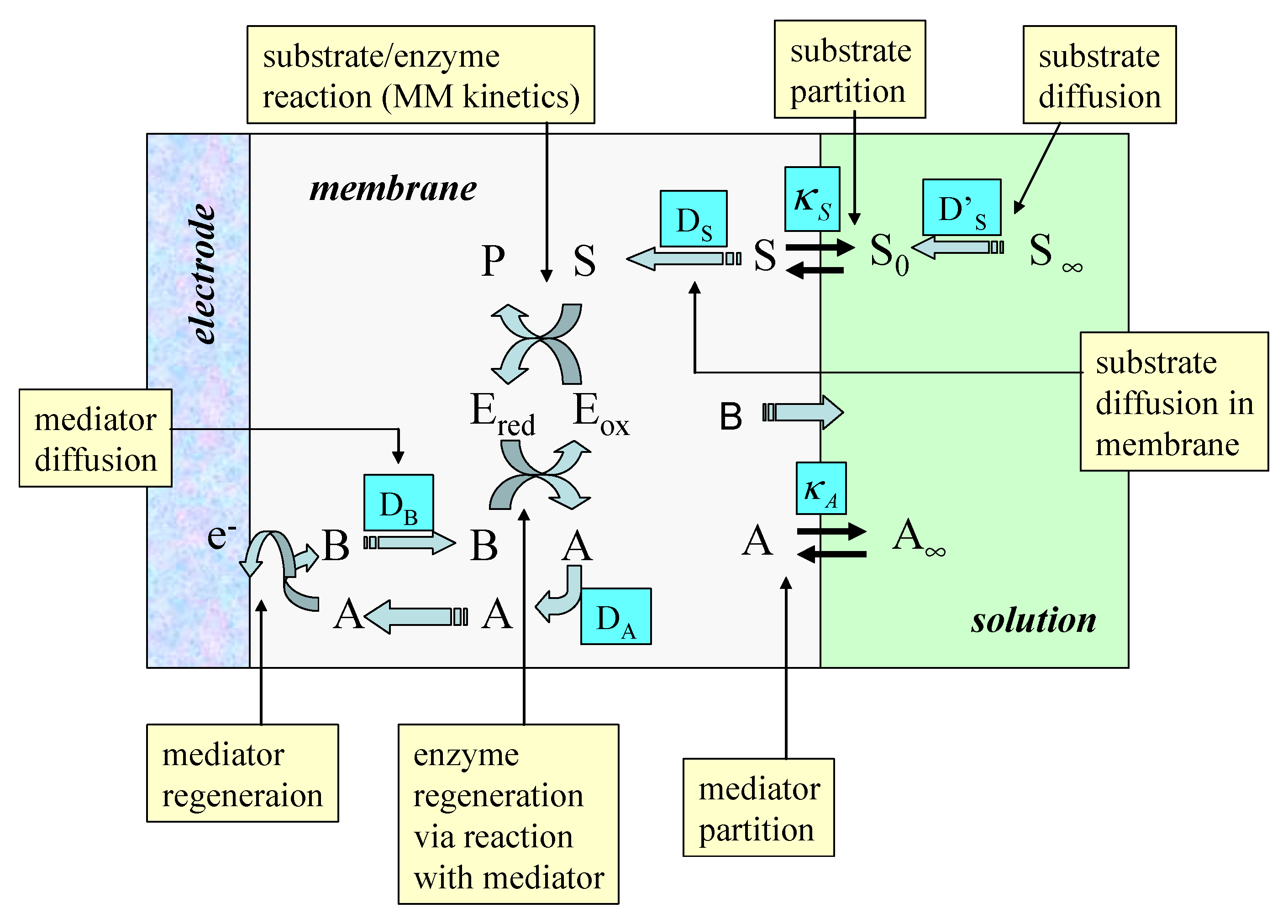
Figure 2.
Schematic representation of immobilized enzyme electrode using a soluble redox mediator. A denotes the oxidized mediator, B is the reduced mediator. Concentration polarization of substrate S and mediator within the enzyme layer is neglected but a Nernst diffusion layer treatment for substrate and mediator transport in the solution is adopted.
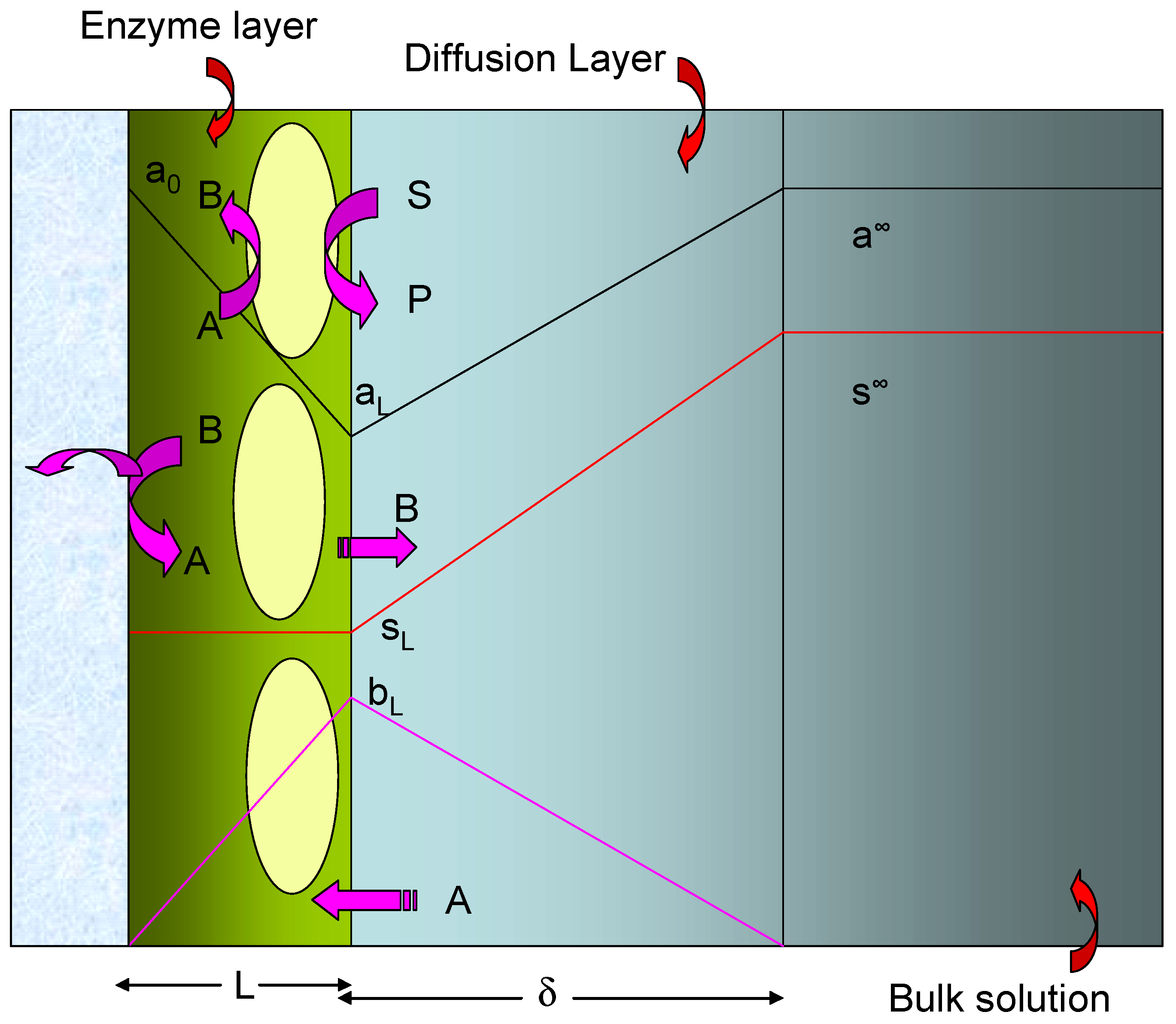
Figure 3.
Kinetic case diagram for an immobilized enzyme monolayer system.

Figure 4.
Variation of the normalized substrate flux with the kinetic competition parameter γ computed from eqn. 20. The plots are computed for different values of the substrate saturation parmeter α. Each set of curves corresponds to a fixed value of the mediator saturation parameter β.
Figure 4.
Variation of the normalized substrate flux with the kinetic competition parameter γ computed from eqn. 20. The plots are computed for different values of the substrate saturation parmeter α. Each set of curves corresponds to a fixed value of the mediator saturation parameter β.

Figure 5.
Variation of the normalized substrate flux with the mediator saturation parameter β computed from eqn. 20. The plots are computed for different values of the kinetic competiton parmeter γ which compares the mediator/enzyme reaction flux to the substrate/enzyme reaction flux. Each set of curves correspond to a fixed value of the substrate saturation parameter α.

Figure 7.
Variation of the flux efficiency factor η with the mediator diffusive flux ratio Φ.

Figure 8.
Plot of inverse current versus inverse substrate concentration for a biosensor consisting of glucose oxidase immobilized within an MPA (3-mercaptopropionic acid) self assembled monolayer using benzoquinone as a soluble mediator. The graph is constructed from batch amperometry data published by Goodring et al [3c]. Enzyme loading = 0.7 pmol cm−2, [benzoquinone] = 1 mM.


| Kinetic Case | Normalised substrate flux | Substrate Flux |
|---|---|---|
| IA Unsaturated mediator kinetics |  | |
| IB Unsaturated enzyme kinetics |  | |
| II Saturated enzyme kinetics | ||
| III Saturated mediator kinetics |
| Reaction Order | a∞ | s∞ | ΓΣ |
|---|---|---|---|
| IA Unsaturated mediator kinetics | 1 | 0 | 1 |
| IB Unsaturated enzyme kinetics | 0 | 1 | 1 |
| II Saturated enzyme kinetics | 0 | 0 | 1 |
| III Saturated mediator kinetics | 0 | 0 | 1 |
© 2003 by MDPI (http://www.mdpi.net). Reproduction is permitted for noncommercial purposes.
Share and Cite
MDPI and ACS Style
Lyons, M.E.G. Mediated Electron Transfer at Redox Active Monolayers. Part 4: Kinetics of Redox Enzymes Coupled With Electron Mediators. Sensors 2003, 3, 19-42. https://doi.org/10.3390/s30200019
AMA Style
Lyons MEG. Mediated Electron Transfer at Redox Active Monolayers. Part 4: Kinetics of Redox Enzymes Coupled With Electron Mediators. Sensors. 2003; 3(2):19-42. https://doi.org/10.3390/s30200019
Chicago/Turabian StyleLyons, Michael E.G. 2003. "Mediated Electron Transfer at Redox Active Monolayers. Part 4: Kinetics of Redox Enzymes Coupled With Electron Mediators" Sensors 3, no. 2: 19-42. https://doi.org/10.3390/s30200019