Experimental Determination of Bending Resonances of Millimeter Size PVF2 Cantilevers

1
Department of Materials Science and Engineering, University of Cincinnati, Cincinnati, OH 45221- 0012, USA
2
Structural Dynamics Research Laboratory, Department of Mechanical, Industrial and Nuclear Engineering, University of Cincinnati, Cincinnati, OH 45221-0072, USA
*
Author to whom correspondence should be addressed.
Sensors 2003, 3(7), 263-275; https://doi.org/10.3390/s30700263
Submission received: 20 May 2003
/
Accepted: 6 July 2003
/
Published: 27 July 2003
Abstract
:The polymer piezoelectric polvinylidene fluoride has found widespread use in sensors and actuators. The bending mode of piezoelectricity offers very high sensitivities and low mechanical input impedance, but has not been studied in as much detail for sensor applications. We report the dynamic electromechanical properties of millimeter size cantilevers made from electroded films of PVF2. All devices tested had a single polymer layer. Several resonances are found below 1 kHz and the experimentally observed resonance frequency dependence on cantilever thickness and length are seen to agree well with published models which take the properties of the electrodes into account. It is found that bending resonances are also modulated by the width of the cantilever. Therefore, though the length and thickness control the resonance frequency most strongly, the actual realized value can be fine-tuned by changing cantilever width and the electrode material and its thickness. Further, all resonances display high piezoelectric coupling coefficients (keff), ranging between 0.2 - 0.35. The data presented here will be extremely useful in the design of sensors and actuators for a number of applications, since the combination of millimeter size scales and high piezoelectric sensitivities in the low audio range can be realized with this marriage of polymeric materials and cantilever geometries. Such an array of sensors can be used in cochlear implant applications, and when integrated with a resonance interrogation circuit can be used for the detection of low frequency vibrations of large structures. If appropriate mass/elasticity sensitive layers are coated on the electrodes, such a sensor can be used for the detection of a wide range of chemicals and biochemicals.
Introduction
Since the discovery of piezoelectricity in the polymer polyvinylidene fluoride (PVF2) [1], this material and its copolymers have made possible a large number of new transducer applications [2], including widespread use in structural active-passive damping applications. Polymer piezoelectrics offer a number of advantages over their ceramic counterparts, chief among them being ease of fabrication into films, flexibility, high voltage sensitivity (piezoelectric g-coefficient), high dielectric breakdown strength (enabling high power devices) and better acoustic impedance matching with air and water. They have been used in novel configurations to extract larger displacements. At present there is an increasing need for small sized high sensitivity devices for various applications. The feasibility of a piezoelectric device based cochlear implant has recently been discussed by two of the authors [3] and polymer piezoelectric devices utilizing bending (flexure) mode piezoelectricity have been proposed [4,5]. Bending mode piezoelectricity [4,6,7] offers very high sensitivity and the effect is described by the following equation [4,7]:
where D3 and E3 are the dielectric displacement and the electric field, respectively, in the thickness direction, ε3 the dielectric constant, R is the radius of curvature for bending deformation, and β331 is defined as the bending piezoelectric constant. If a cantilever film of thickness t, length l, width h and capacitance Co is bent by x distance at the tip, and the voltage generated is V3, then β331 is given as [7]:
where both Equations 1 and 2 are in CGS units. The performance characteristics of polymer piezoelectric flexure mode devices under dynamic conditions have been evaluated theoretically [8], but no experimentally determined modal models or modal dependence on material properties of piezoelectric and electrode materials are available. Such data will be of great significance in facilitating the design of small size acoustic sensors, since the relatively soft nature of the polymeric material combined with the nature of bending vibrations implies resonance frequencies well below 1 kHz in even millimeter sized devices. This study was conducted to determine the nature of bending vibration modes in small lengths (2 - 20 mm) of cantilever single layer PVF2 devices and their electromechanical coupling. It is of importance to understand the effect of film parameters (length, width, and thickness), and electrode parameters (stiffness, thickness), on the frequency and damping behavior of the system. Experimental modal analysis has been employed for this purpose. The final goal of this work is to enable future design of sensors and actuators in many applications, including cochlear implants [3]. It is seen that though the experimental data agrees well with published theoretical equations [8], certain inconsistencies are observed and can be ascribed to the complex nature of bending piezoelectric coupling in polymers [6,9,10,11,12,13], and the dynamics associated with the small scale of the device. Electrode parameters are also seen to significantly affect the response of the cantilever.
Experimental Details
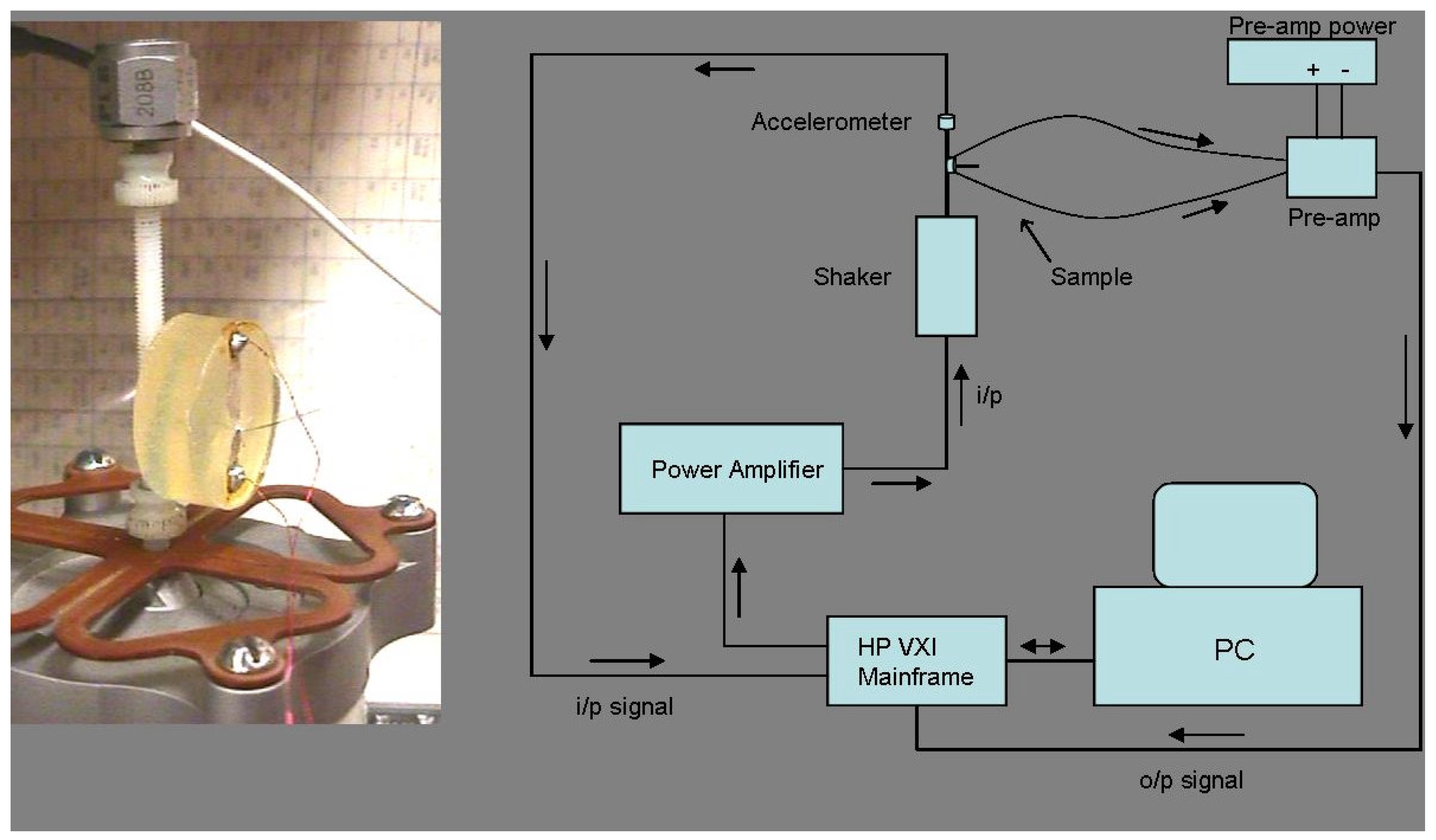
Polymer piezoelectric films with Nickel-Copper electrodes and of thicknesses 28μm and 52μm were obtained from Measurement Specialties Inc., USA. Electrode thickness was of the order of 700Å for both the films, being the same on both sides of the film. Strips of film of appropriate dimensions were cut from the sheets supplied, in all cases the long axis of the strips coinciding with the film rolling/stretching direction, i.e., the ‘1’ direction [11]. The width of the strips coincided with the ‘2’ direction and the thickness the ‘3’ direction. Strips were mounted as cantilevers in a base cast from Lecoset 7007TM (acrylic powder plus liquid) self-curing mixture (Figure 1). The proportion of liquid was intentionally kept high in the mixture to facilitate lower curing temperatures (< 60oC) and prevent heat damage to the piezoelectric film. Electrical connections were made to the film electrodes using SPI, Inc. high purity Silver Paste PlusTM. Copper wires were soldered to the silver paste at the ends of the acrylic base.
The excitation signal (burst-random) was generated in Matlab and a MB Dynamics amplifier was used to drive a Ling Dynamics model V203 shaker. A calibrated accelerometer (PCB Piezotronics) was placed at the tip of the shaker to measure the input driving signal (Figure 1). A HP-VXI mainframe 8084A was used for data acquisition. The sampling rate was chosen to obtain the desired frequency resolution of 0.5 Hz in a range of 0 to 800 Hz. The device was mounted on the shaker for a driving point measurement, such as to excite the bending modes. The voltage generated by the film was introduced into a DL Instruments 125L unity-gain impedance transfer pre-amp and was the response signal for the driving point measurement. The maximum voltage response from the devices ranged between 100 - 500 mV, and did not vary with cantilever length. Figure 1 shows a photograph and schematic of the experimental set-up.
A typical modal analysis experiment on a non-piezoelectric material would involve the measurement of mechanical displacements of the specimen. In the present case, the piezoelectric activity of the samples enabled the direct measurement of the electrical voltage generated across the film electrodes in response to the random mechanical energy input. The input was the excitation voltage to the shaker and the output was the piezoelectric voltage generated by the cantilever device. Such an experiment serves the dual purpose of enabling the measurement of both modal parameters and electromechanical energy conversion parameters simultaneously, the caveat being that mechanical resonances in the frequency range of measurement should have electromechanical coupling.
Modal parameters are estimated frequency response measurements. These frequency response function (FRF) measurements H(ω)=X(ω)/F(ω) within the frequency domain correspond to an autoregressive moving average model that is developed from a set of finite difference equations within the time domain. To reduce the effect of noise on the output, an H1 algorithm [14] is used to compute the modal frequencies and mode shapes. This algorithm results in underestimates of damping and amplitudes at resonance as well as anti-resonance. The FRF is computed as a ratio of the cross power spectrum and auto power spectrum computed at input point p and output point q.
The ordinary coherence is defined as the correlation coefficient describing the linear relationship between any two spectra.
The excitation signal used was burst random, which is neither a completely transient deterministic signal nor a completely ergodic, stationary random signal but contains properties of both signal types. The frequency distribution of this signal type has random amplitude and random phase distribution and contains energy throughout the frequency spectrum, reducing leakage. Force and exponential windows used on the input and output signals, respectively, reduce noise and improve coherence. Also used in this analysis was the Complex Mode Indication Function (CMIF) [15], an algorithm based on singular value decomposition methods, which, when applied to multiple reference FRF measurements yields the corresponding mode shapes and modal participation vector. For modal parameter (frequency and damping) estimation, X-ModalTM software [16], developed by the Structural Dynamics Research Laboratory at University of Cincinnati was used. The data was first observed using a CMIF plot so that the well excited modal frequencies could be identified. An estimate of the modes was found using the poly-reference time domain algorithm (chosen because of its short computation time) with a modal order of 2 to 5 [15].
The films used for the experiments were not straight cantilevers for large lengths, but curved beams. This can create a nonlinearity in the response, and is due to the inherent nature of the films. Further, the effect of the mount is to create a stiff boundary condition which actually leads to the intended cantilever type configuration (fixed-free). Limitations of modal testing arise due to: 1) The inability of the shaker to input energy at high frequencies [17], and; 2) The fact that modal parameter estimation techniques do not lend themselves well to the very low frequency range [17]. Other device non-linearities can arise due to the aspect ratio, the viscoelasticity of the material, and the microscopically heterogeneous nature of semicrystalline polymers (amorphous phase + crystalline phase).
3. Results and Discussion
Modal Frequency Dependence on Cantilever Length and Thickness
This experiment was performed to obtain the frequencies and damping of the modes of interest, and study the effect of various geometric parameters on piezoelectric properties. A typical FRF (raw data) over the frequency range of measurement (65 - 800 Hz) is shown in Figure 2(a). Two distinct resonances, corresponding to modes II and III are observed in this plot. The first mode only became visible (i.e., > 65 Hz) at smaller lengths, and is hence not seen in Figure 2(a). A sharp peak at 60 Hz arises due to electromagnetic noise and its tail is visible in Figure 2(a). Most of the resonances displayed a damping of < 2 percent.
It was observed that as the cantilever length was decreased (all other parameters being kept constant), the resonance frequencies shifted to higher values. Typical behavior is shown in Figure 2(b), where the resonance frequency is seen to shift from ~ 220 Hz to ~ 380 Hz as the cantilever length is changed from 20.75 mm to 15.5 mm. All three modes observed displayed this type of behavior.
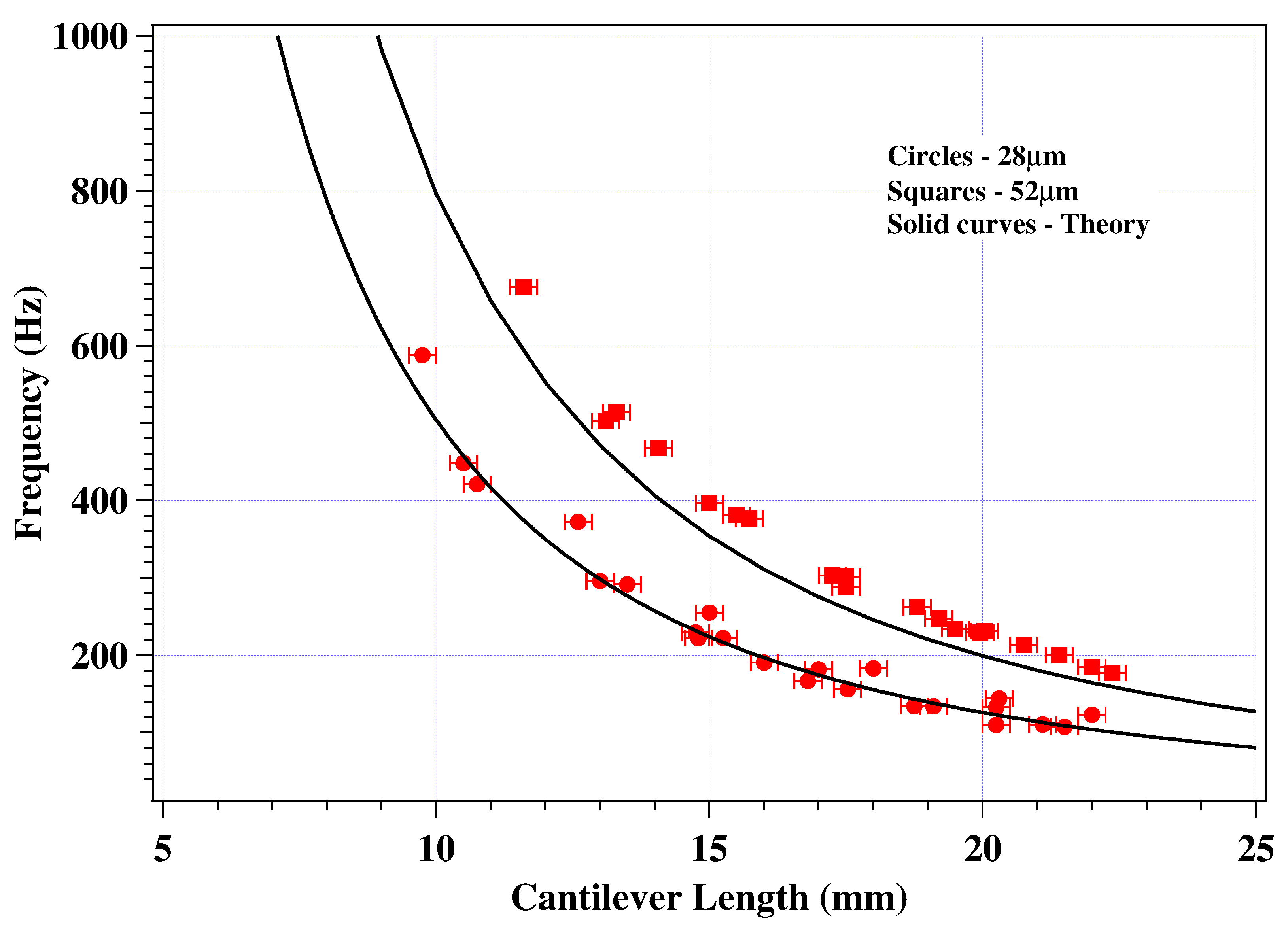
This dependence of the frequencies of the first three bending modes on cantilever length is plotted in Figure 3. Figure 3(a) shows the behavior of 28μm thick films and Figure 3(b) that of 52μm thick films. In both the plots, the experimental data (resonance frequency versus cantilever length) are depicted by symbols. The round set of symbols represent first mode resonances, the square set of symbols second mode resonances, and the third mode is represented by the triangular or third set of symbols. In the case of each film, four different devices of different widths were tested, as noted by Sample 1 through Sample 4 within each set of symbols. The error in the measurement of the cantilever length is estimated to be ± 0.25 mm, and is depicted by error bars in the plots. The error in the measurement of frequencies is estimated to be ± 1 Hz and is not depicted in the plots. The curves observed in these plots are those obtained from theoretical models and are discussed below.
Figure 2.
(a) A typical raw data FRF of a PVF2 cantilever device in the frequency range 65 - 800 Hz. (b) FRF’s showing the shift in resonance frequencies with cantilever length.
Figure 2.
(a) A typical raw data FRF of a PVF2 cantilever device in the frequency range 65 - 800 Hz. (b) FRF’s showing the shift in resonance frequencies with cantilever length.

It is observed from Figures 3(a) and (b) that the experimental data obtained from different devices are quite similar. A width dependence on modal frequencies is observed, however, and is discussed in the next section. The thickness dependence of modal frequencies is made evident by re-plotting the IInd mode from Figures 3(a) and (b), as shown in Figure 4. It is seen that decreasing thickness lowers the resonance frequencies, in a manner similar to that predicted by theoretical models described below.
Figure 3.
The resonance frequency dependence of the first three bending vibration modes in PVF2 cantilevers. (a) for 28μm thick films; (b) for 52μm thick films. Several devices of varying widths were tested as indicated. Dotted curves represent theoretical behavior not incorporating the effect of the electrodes (Equation 5). Solid curves represent theoretical behavior(Equations 6 – 8).

incorporating electrode effects.
Figure 4.
The dependence of resonance frequency on the film thickness. The specific mode shown here is Mode II.
Figure 4.
The dependence of resonance frequency on the film thickness. The specific mode shown here is Mode II.

In the following, the experimental data obtained is compared with theoretical models available in literature. In the simplest model, the natural frequency of a cantilever beam can be determined by the following equation [18]:
where E is the Young’s modulus, I is the moment of inertia, μ is the mass per unit length of beam, l is the length, and A is a coefficient which changes with the mode number (A = 3.52 for Mode I; 22 for Mode II; 61.7 for Mode III [18]). Substituting the appropriate material properties of PVF2, the theoretical modal frequency dependence on cantilever length can be determined and are plotted as dashed curves in Figures 3(a) and (b). It is seen that the measured data and the theoretical curves do not match. However, this difference is due to the presence of the metallic electrodes on either side of the PVF2 film, effectively making the device a three layered composite. The large difference between the elastic modulii of the polymeric film and the metallic electrodes result in the electrodes significantly modifying the resonance frequency, despite their thickness being small compared to that of the film. In a more advanced model, taking the properties of the electrodes into account, Marcus [8] derived the fundamental (mode I) resonance frequency of a piezoelectric unimorph cantilever to be:
where h is the thickness, l is the length, Et, Ep and Em and ρt, ρp and ρm are the elastic modulii and densities of the upper electrode, polymer and lower electrode, respectively, n defines the position of the neutral plane (as fraction of total thickness, measured from the lower electrode), a and b are the fractional contributions to the total thickness made by the upper and the lower electrodes, respectively. In the present case, the electrodes are of the same material and thickness on both sides. Therefore, Et = Em; n = 0.5; a = b; and ρt = ρm, and Equation 6 reduces to,
for 28μm devices (since, a = b = 2.5 x 10⁻³), and,
for 52μm devices (since, a = b = 1.35 x 10⁻³).
Substituting the relevant dimensions and material parameters (Ep = EPVF2 = 2.5 GPa [2]; Et = ENickel = 207 GPa [19]; ρn = ρPVF2 = 1.78 x 10³ kg/m3 [2]; ρt = ρNickel = 8.903 x 10³ kg/m3 [19]) in the above equations, the fundamental (Ist mode) resonance frequencies can be calculated and are plotted as solid curves in Figures 3(a) and (b). These curves are seen to match the experimental data (round symbols) quite well. Since the Nickel-Copper alloy electrode was primarily Nickel (actual composition proprietary), the elastic modulus of pure Nickel has been used in the above. The frequencies for the IInd and the IIIrd modes can also be determined by knowing the factors relating the modes (see Equation 5) [18]:
The IInd and IIIrd modes, thus calculated, are also plotted as solid curves in Figures 3(a) and (b). These curves are also seen to fit the experimental data quite well in the case of the 28μm devices but not agree as well with the data obtained from the 52μm devices, though similar trends are observed in experiment and theory. This discrepancy may arise because the actual factors relating the modes may be different than those used here (Equation 9).
Thus it is seen that the behavior observed experimentally can be explained by Equations 6 - 9. However, this model does not fit the data quite as well in some cases and is also not able to predict the width dependence of modal frequencies. Overall, the length and thickness of the cantilever control the resonance frequency most strongly, but small changes can be brought about by choosing an electrode of appropriate Young’s modulus and modulating its thickness. These findings are of importance to the device designer. The effect of the cantilever width also, however, needs to be taken into account, as described next.
The Effect of Cantilever Width
The equations of pure bending vibrations of cantilever beams do not predict a modal frequency dependence on the width of the cantilever (see Equation 6). In the data presented above, however, such a dependence is clearly evident (see Figures 3(a) and (b)). Increasing the width leads to an observed increase in the modal frequencies. This dependence is observed to be stronger in the case of the 28μm thick films. In this regard, it should be mentioned that though the data presented above were acquired from devices with widths ranging from approximately 2 mm to approximately 0.75 mm, several devices with width approximately 5 mm were also tested. In this case the observed spectra were much more complicated, with several resonances occurring, many of which did not shift as the length was decreased. Physically, this width dependence is believed to be due to the coupling between pure bending vibration (primary mode of excitation) and transverse vibration of the cantilevers, inherently unavoidable in multilayered media [20]. The devices tested were, from an acoustic perspective, three layered composites (electrode + polymer + electrode). Further, the lamellar morphology of piezoelectric (β phase) PVF2 [21] suggests that the polymer itself may not behave wholly as a homogeneous continuum for acoustic purposes. Transverse vibrations generated in the film plane in the direction perpendicular to the length, i.e., in the ‘2’ direction, will be sensitive to the width of the cantilever and are the likely physical cause of this dependence. The reason the Marcus model is unable to account for the width dependence is because it uses the equations of bending of beams; models based on equations of bending of plates are likely to better predict the width dependence. This is a significant experimental finding, since in some cases the change in modal frequencies with small changes in sample width is quite substantial (see Figure 3(a)). Also, millimeter length devices with widths much larger than approximately 2 mm are likely to display complicated frequency spectra, making it difficult for them to be used in resonator type applications. Thus, the width of the cantilever is also an important parameter and must be accounted for during the design of sensors and actuators.
Piezoelectric Coupling Coefficient
The electromechanical coupling coefficient (keff) is a measure of the amount of total energy transduced at resonance and is used to quantify the piezoelectric activity of devices at resonance. The resonance parameters of an equivalent electrical circuit are usually used to determine keff [22]. In the present case, the frequency of maximum FRF amplitude (fmax) and frequency of minimum FRF amplitude (fmin) (see Figure 2) have been used to approximately determined keff, using the following equation:
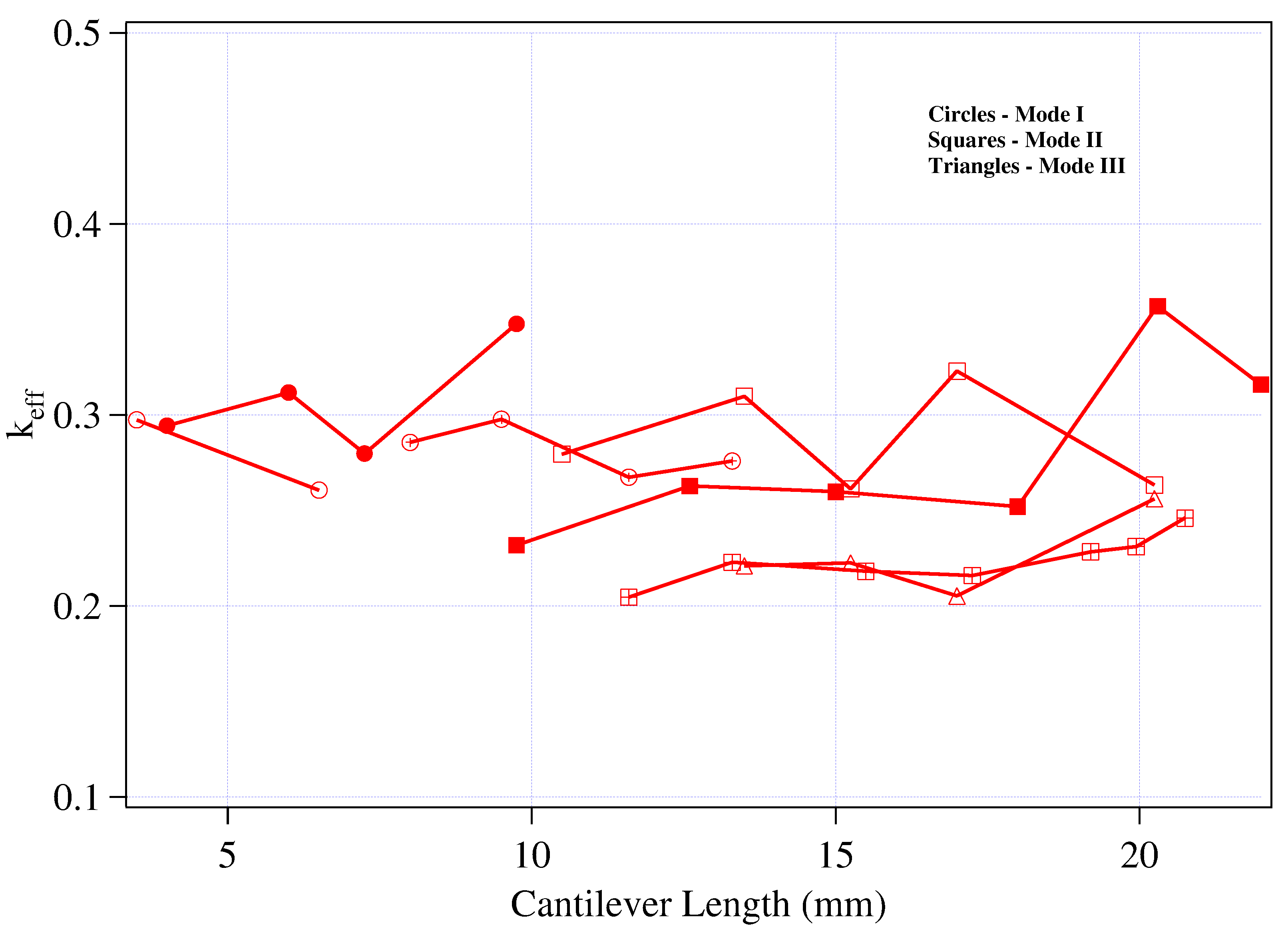
The keff values for typical samples are plotted versus the cantilever length in Figure 5. The values are seen to be in the 0.20 to 0.35 range and more or less constant as the cantilever length is changed. This is significant, since it implies that the piezoelectric coupling does not diminish as the sample length is decreased (stiffness increased). Also, compared to other piezoelectric materials and vibration modes [22], these values are high, indicating a strong coupling in the bending mode.
Conclusions
Experimental vibrational analysis of the piezoelectric polymer PVF2 has been performed. Devices tested were of cantilever geometry, electroded with Nickel-Copper on both sides, of length 2 - 25 mm and width 0.75 – 2 mm. The experimental data confirms, as predicted by theory, the existence of several resonances below 1 kHz, and the modal frequency dependence on cantilever length is also similar to that predicted by theoretical equations. It was observed experimentally that the width of the cantilever modulates the resonance frequency. This is thought to be due to the coupling of bending and transverse vibrations in multilayered media. All resonances were observed to have reasonably high piezoelectric coupling coefficients, between 0.20 to 0.35, which did not change appreciably with cantilever length. This data will be useful in the design of small piezoelectric sensors and actuators with enhanced performance in the low audio frequency range. For instance, an array of these sensors can be used for quick detection of low frequency vibrations of large structures. If appropriate mass/elasticity changing polymers are coated on the electrodes, these type devices can be used as chemical sensors.
Acknowledgements
RDR gratefully acknowledges the support of the National Science Foundation, under grant number ECS0100199, which made this research possible. The use of facilities at the Structural Dynamics Research Lab at the University of Cincinnati is also gratefully acknowledged.
References
- Kawai, H. The piezoelectricity of poly(vinylidene fluoride). Japan J. Appl. Phys. 1969, 8, 895. [Google Scholar] [CrossRef]
- Gallantree, H.R. Review of transducer applications of polyvinilidene fluoride. IEE Transactions 1983, 130, 219. [Google Scholar]
- Mukherjee, N.; Roseman, R. D.; Willging, J. P. The piezoelectric cochlear implant: Concept, feasibility, challenges and issues. J. Biomed. Matls. Res. (Appl. Biomat.) 2000, 53, 181–187. [Google Scholar] [CrossRef]
- Kawai, H. Bending piezoelectricity of elongated polymer films. Oyo Buturi 1970, 39, 869. [Google Scholar]
- Mukherjee, N.; Roseman, R. D. Considerations in the development of a piezoelectric cochlear implant. MRS Symp. Procs. 2000, 604, 79–84. [Google Scholar] [CrossRef]
- Furukawa, T.; Uematsu, Y.; Asakawa, K.; Wada, Y. Piezoelectricity, pyroelectricity, and thermoelectricity of polymer films. J. Appl. Pol. Sci. 1968, 12, 2675. [Google Scholar] [CrossRef]
- Ibe, T. Bending piezoelectricity in polytetrafluoroethylene. Japan J. Appl. Phys. 1974, 13, 197. [Google Scholar] [CrossRef]
- Marcus, Michael A. Performance characteristics of piezoelectric flexure mode devices. Ferroelectrics 1984, 57, 203–220. [Google Scholar] [CrossRef]
- Murayama, Naohiro; Hashizume, Hideyuki. Persistent polarization in poly(vinylidene fluoride) iii. Depolarization and pyroelectricity of poly(vinylidene fluoride) thermoelectrets. J. of Polym. Sci. Polym. Phys. Edn. 1976, 14, 989–1003. [Google Scholar] [CrossRef]
- Broadhurst, M. G.; Davis, G. T.; McKinney, J. E.; Collins, R. E. Piezo- electricity and pyroelectricity in polyvinylidene fluoride-a model. J. Appl. Phys. 1978, 49, 4992–4997. [Google Scholar] [CrossRef]
- Lovinger, Andrew J. Ferroelectric polymers. Science 1984, 220, 1115–1121. [Google Scholar] [CrossRef] [PubMed]
- Fukada, E.; Sesler, G. M.; West, J. E.; Berraissoul, A.; Gunther, P. Bending piezoelectricity in monomorph polymorph films. J. Appl. Phys. 1987, 62, 3643–3646. [Google Scholar] [CrossRef]
- Wintle, H. J.; Dorsam, R. Phenomenological piezoelectricity of polymer insulators. Physical Review B 1989, 39, 3862–3870. [Google Scholar] [CrossRef] [PubMed]
- Vold, H.; Crowley, J.; Rocklin, G. A comparison of h1, h2 and hv frequency response functions. Proceedings of the International Modal Analysis Conference 1985, 272–278. [Google Scholar]
- Allemang, R. J.; Brown, D. L. A unified matrix polynomial approach to modal identification. J. Sound and Vibration 1998, 211, 301–322. [Google Scholar] [CrossRef]
- More information regarding XModal can be found at. http://www.sdrl.uc.edu.
- Ewins, D.J. Modal Testing: Theory and Practice; pg 269; Research Studies Press, John Wiley and Sons, 1984. [Google Scholar]
- Rothbart, H. A. (Ed.) Mechanical Design Handbook; McGraw Hill, 1996; pp. 5.1–5.83. [Google Scholar]
- Metals Handbook, volume 2, chapter: Properties of Pure Metals, page 777. Am. Soc. for Metals, 9th edition. 1979.
- Heckl, M.A. Handbook of Acoustics; chapter 49, page 591; Wiley-Interscience, 1998. [Google Scholar]
- Legrand, J. F.; Lajzerowicz, J. S.A.X.S. investigation of the lamellar morphology in rolled and poled PVF2 thick films. Ferroelectrics 1983, 51, 129–135. [Google Scholar] [CrossRef]
- Molson, A. J.; Herbert, J. M. Electroceramics; chapter 6, page 274; Chapman and Hall, 1990. [Google Scholar]
Sample Availability: Available from the authors. |
Figure 1.
Photograph and schematic of experimental setup.

Figure 5.
Effective bending piezoelectric coupling coefficient (keff) versus cantilever length. High values between 0.20 - 0.35 occur for all three modes and sustain throughout the range of length tested.
Figure 5.
Effective bending piezoelectric coupling coefficient (keff) versus cantilever length. High values between 0.20 - 0.35 occur for all three modes and sustain throughout the range of length tested.

Publisher’s Note: MDPI stays neutral with regard to jurisdictional claims in published maps and institutional affiliations. |
© 2003 by MDPI (http://www.mdpi.org). Reproduction is permitted for noncommercial purposes.
Share and Cite
MDPI and ACS Style
Mukherjee, N.; Shukla, A.; Roseman, R.D.; Thompson, D.F. Experimental Determination of Bending Resonances of Millimeter Size PVF2 Cantilevers. Sensors 2003, 3, 263-275. https://doi.org/10.3390/s30700263
AMA Style
Mukherjee N, Shukla A, Roseman RD, Thompson DF. Experimental Determination of Bending Resonances of Millimeter Size PVF2 Cantilevers. Sensors. 2003; 3(7):263-275. https://doi.org/10.3390/s30700263
Chicago/Turabian StyleMukherjee, Niloy, Amit Shukla, Rodney D. Roseman, and David F. Thompson. 2003. "Experimental Determination of Bending Resonances of Millimeter Size PVF2 Cantilevers" Sensors 3, no. 7: 263-275. https://doi.org/10.3390/s30700263