1. Introduction
Medicine, law enforcement, national security, environmental compliance and industrial processes monitoring and control are among the large number of applications that require chemical sensing capabilities. These applications require sensitive, non-destructive, rapid detection and quantification of the chemicals of interest [
1]. Most chemical sensing methods are expensive, time consuming, and/or limited in the sampling and analytical techniques which can be applied [
2]. Furthermore, only a few laboratory-based sensing techniques have been demonstrated for long-term field measurement applications [
3].
Optical sensing techniques have some inherent advantages over other non-optical sensing techniques. Among these advantages are: (a) immunity to electromagnetic interference since the optical components are highly electrically resistive materials, (b) insensitivity to environmental variations such as temperature and pressure for certain optical sensor designs, and (c) the capability of sensing without having the electronic components located at the measurement environment. Furthermore, the ready availability and continuous development of optical components and instrumentation from the optical communication industry provides an economic advantage to optical sensors. In addition, the use of optical waveguides can provide lower losses over long distances, adding more advantage to the broad area of optical sensing. Optical waveguides can be produced from different materials such as glass, plastic and single crystals. They are relatively inexpensive (except for certain single crystal fibers), robust, flexible, chemically inert, and biocompatible. They also have small physical dimensions, and can be sterilized. Waveguides, such as optical fibers, planer waveguides and hollow-core waveguides, can deliver light to and from the active sensing element over large distances at different locations via multiplexing. This enables real-time, on-line, and multipoint monitoring of large structures and sensing in remote areas that are hazardous, hostile, or difficult to access [
4].
Since the invention of optical fibers, research groups have developed various types of optical fiber based sensors [
5]. These sensors can be categorized based on light modulation into interferometric and spectroscopic sensors [
6]. Fiber Bragg Gratings (FBG's) sensors are the most common types of the interferometric sensors and they make up a significant part of the recent publications on optical fiber sensors [
5]. Evanescent Field Absorption (EFA) sensors, which fall under the spectroscopic sensors category, are considered to be the most published type of optical fiber sensor [
7]. Hollow-core optical waveguides enabled the development of small sample cell (SC) sensors. Optical fiber based SC sensors are considered to be another type of spectroscopic sensors. All SC sensors reported in [
8-
13] have cell volumes in the 100's of microliters (μL) range, which is relatively large especially in the age of nanotechnology. However, our research group recently reported a SC sensor for multigas sensing with a cell volume of 3.5 μL [
14]. The goal of this work has been to develop and demonstrate a SC gas sensor that has a cell volume in the nanoliter (nL) or sub-nL size range.
Sensor's principle of operation
The use of infra-red (IR) technology in gas sensing is considered one of the most important technologies in industrial, environmental, and safety monitoring [
15]. It has been used to provide high-resolution, non-destructive, sensitive, and fast detection and quantification of technologically important chemical species [
1]. For the past 15 years, it has been demonstrated, as discussed above, that optical fiber based SC sensors are capable of detecting single and/or multiple gases that have absorption spectra in the near infrared region. This includes O
2, NO
2, HF, HBr, H
2O, C
2H
2, HI, NH
3, CO, CO
2, H
2S, CH
4, and HCl [
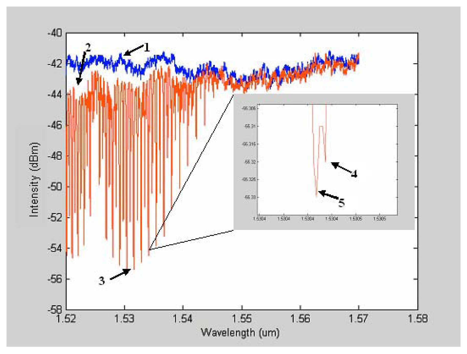
16]. In general, when the IR radiation passes through a gas cell, a part of the radiation energy will be absorbed by the gas molecules resulting in distinctive absorption bands in the absorption spectrum which allows identification of the chemical species (See
figure 1). This spectrum results from the vibrational and rotational energies of the particular species being measured. Incident light, with a frequency equal to one of the vibrational or rotational energies of the species being considered, can be absorbed by the gas species.
As shown in
Figure 1, features 4 and 5 represent the separation of the line's maximum into two maxima. This phenomenon is explained by the isotope effect. The shift of maximum line position is due to the fact that the two isotopes have two different masses. The simultaneous presence of acetylene isotopes gives rise to the splitting of the line maximum [
17]. This ability to separate out even the isotopes of the same gas chemistry shows the tremendous resolving power in the wavelength domain that is afforded by this SNSC type of optical sensor design.
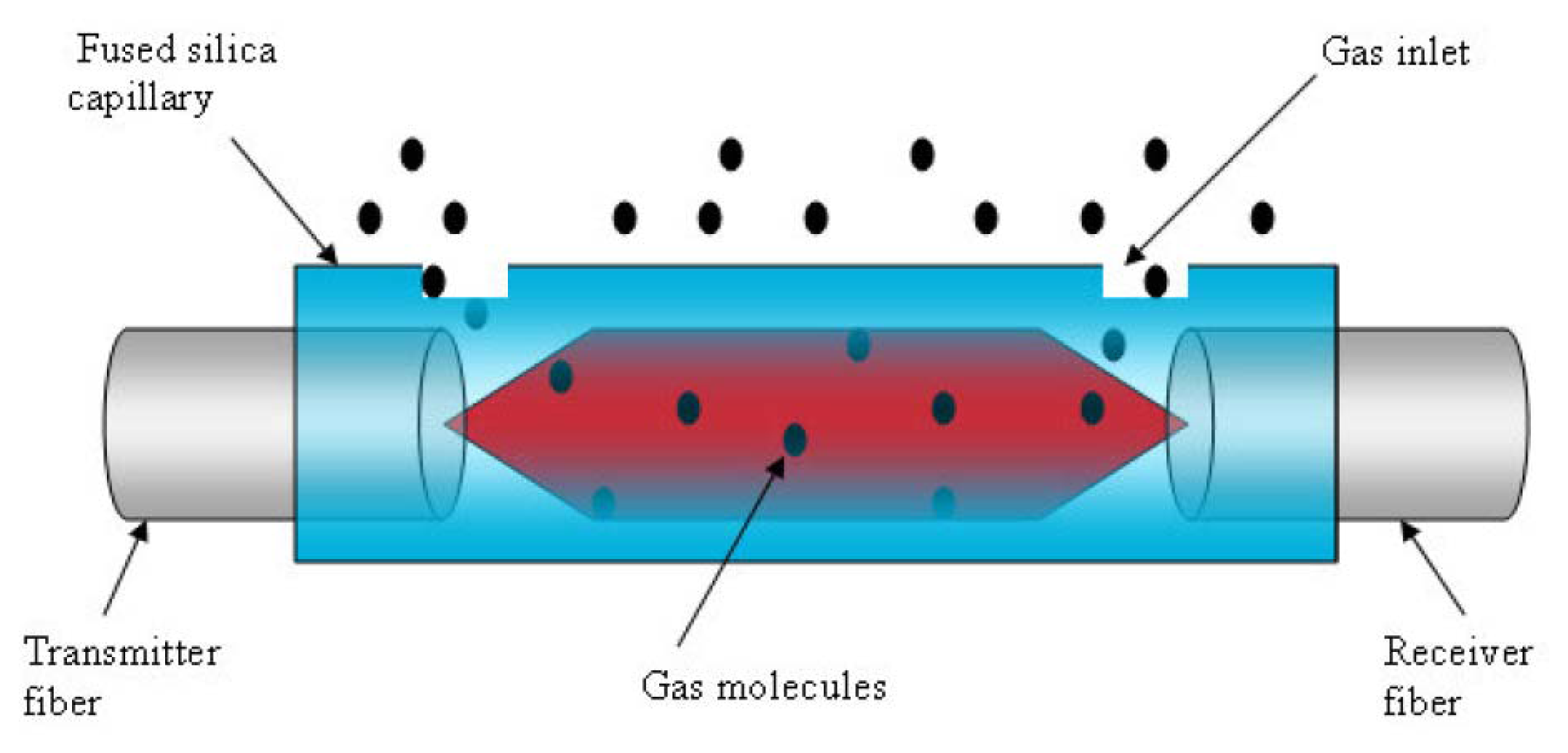
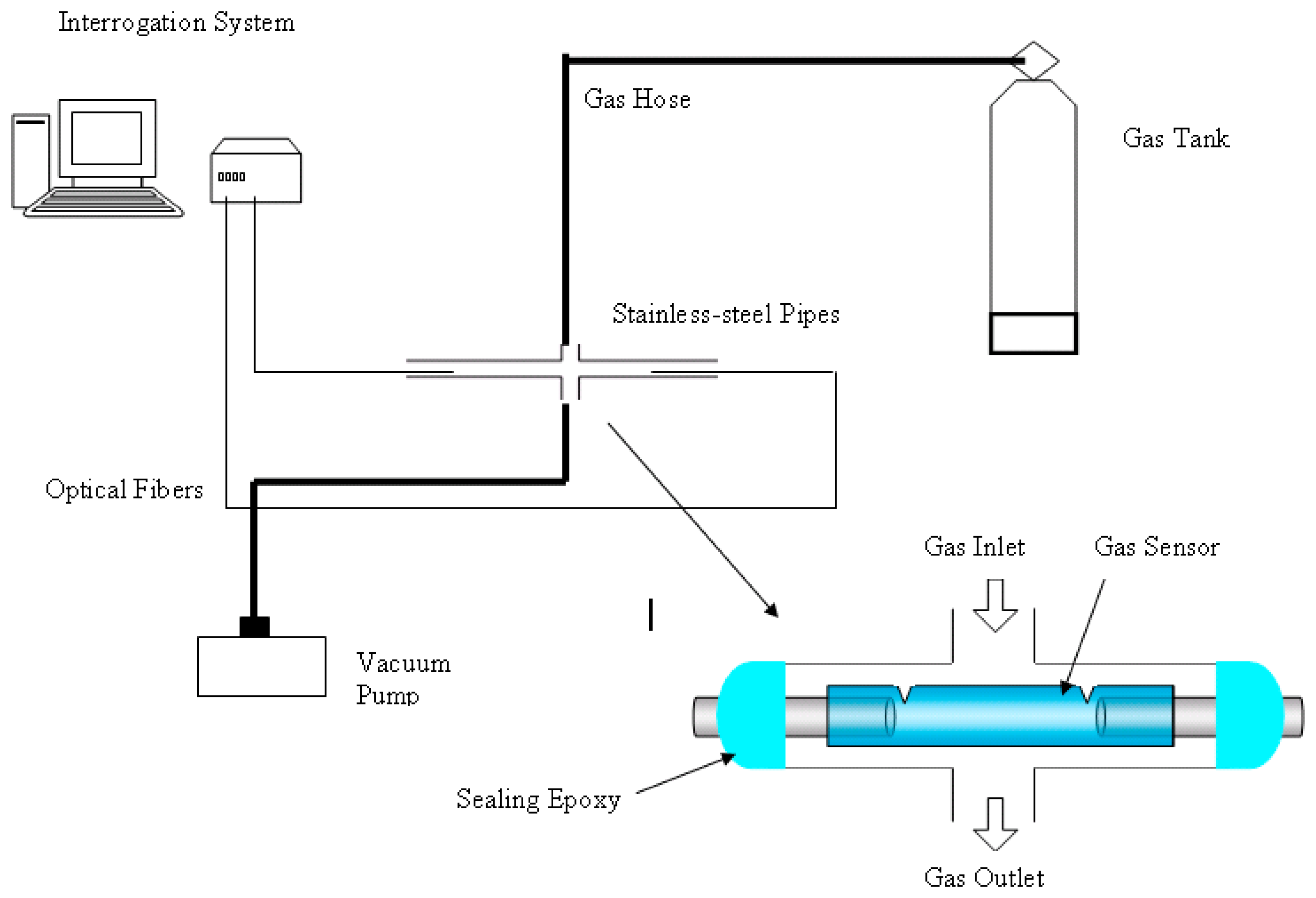
The SNSC sensor consists of an IR source, a gas cell, and an IR detector. An optical fiber, acting as a transmission medium, delivers the IR radiation to the micro capillary tubing which serves in an analogous fashion to the traditional gas cell. The light passes through the sample contained in the micro capillary tubing to another optical fiber, acting as a receiver, which delivers the altered IR radiation to the detector (See
figure 2).
Near-IR spectroscopy is governed by the Beer-Lambert law. In mathematical terms, this relation is expressed as
where
A is the absorbance of the sample,
c is the concentration,
l is the path length of the sample, and ε is a constant that depends on the absorptivity of the species at a particular wavelength. Absorbance is defined as the logarithmic ratio of the intensity of the incident to detected light. In addition, light attenuation should be considered when fabricating a gas cell out of dielectric hollow-core optical waveguide. It has been shown by Miyagi and Nishida that the attenuation constant is related to the wavelength of the light and the hollow core radius by
where
α is the attenuation constant,
λ is wavelength, and
r is the inner radius of the hollow waveguide [
18].
This means that in very small core hollow waveguides there will be more light propagating in the glass wall than in the hollow core. From
equations 1 and
2, one can see that there are trade-offs to be considered in the design of the sensor. The price of decreasing the gas cell dimensions is a decrease in absorbance and an increase in light attenuation. Thus, small gas cell design requires good signal processing techniques to improve signal-to-noise (S/N) ratios. Furthermore, limiting the number of gases to be detected, that is, using a narrow-linewidth optical source increases the value of the absorptivity coefficient. Therefore, it is extremely difficult to realize a sensor with a nL volume gas cell without sacrificing the sensitivity of the sensor and limiting the number of gases to be detected simultaneously.
3. Results and Discussion
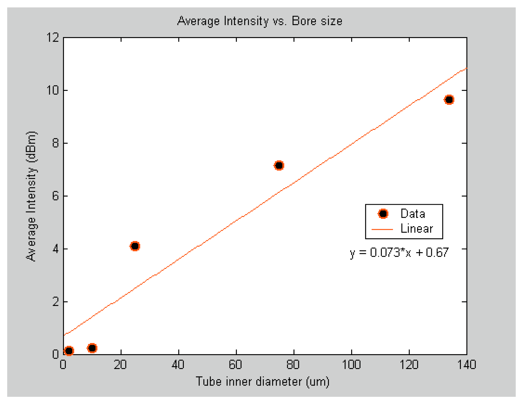
To determine the minimum bore size for the SNSC sensor gas cell, five sensors with the same optical path length of 50 mm and bore size ranging from 2 μm to 134 μm were fabricated and tested under a static pressure of 10 Psi and at room temperature.
Table 1 lists the gas cell bore sizes with their corresponding volumes. Because the absorption spectra consist of a series of absorption lines in two sets, the average of odd number absorption lines of the P-branch that are conventionally labeled from P(1) to P(19) were used to report the results shown in
figure 4. This was done for consistency purposes. Each data point in the
figure 4 represents the average intensity magnitude of the selected 10 absorption lines. The results show a significant drop in the absorption intensity for the 10 μm and 2 μm bore size sensors. The reason for such drop in intensity can be attributed to the fact that more light propagates in the glass wall than in the hollow core. Thus, for reliable detection, the minimum bore size for the gas cell in the SNSC sensor should be around 25 μm.
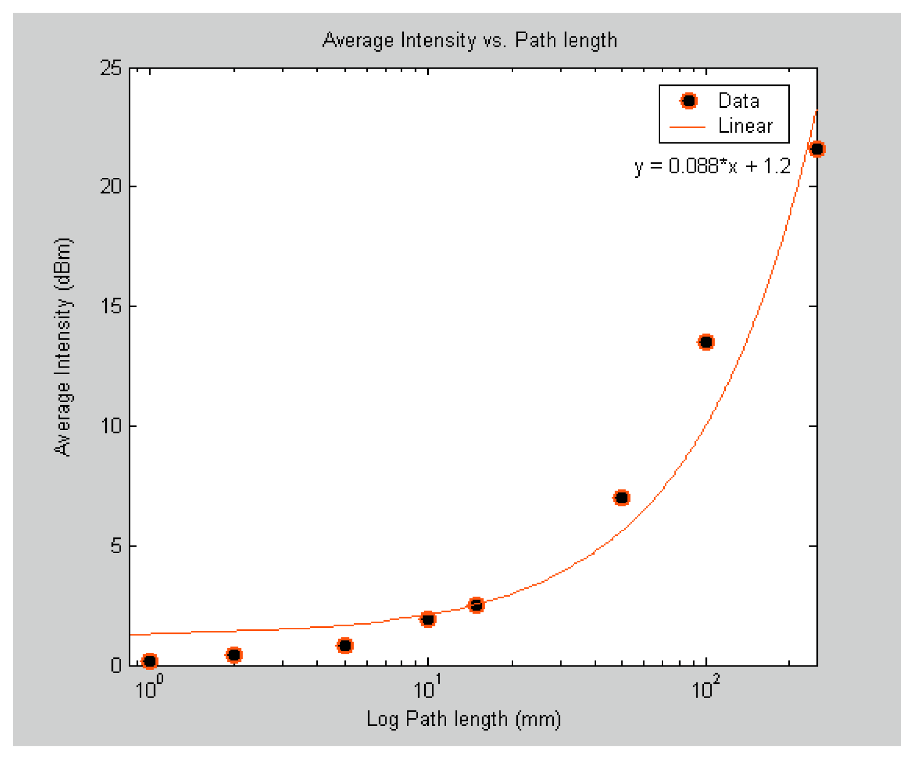
To determine the minimum path length for the gas cell of the SNSC sensor, nine sensors with path lengths ranging from 125 μm to 250 mm were fabricated and tested under a static pressure of 20 Psi at room temperature.
Table 2 lists the gas cell path lengths with their corresponding volumes. Similar to the bore size study, the odd number lines from P(1) to P(19) were measured in each of the nine sensors spectra and then averaged. The results are shown in
figure 5. Each data point in the
figure 5 also represents the average intensity magnitude of the selected 10 absorption lines. The absorption intensities were below the detection limits of the optical interrogation system used for the 0.125 mm path length (not shown in
figure 5). The 1 mm path length sensor showed an average intensity of about 0.18 dBm whereas the 250 mm path length sensor showed an average intensity of 21.6 dBm. Thus, for reliable detection, the minimum path length for the gas cell in the SC sensor should be around 1 mm. According to the results presented, a SC sensor with a gas cell volume as small as 0.5 nL can reliably produce absorption lines above the noise level of the system.
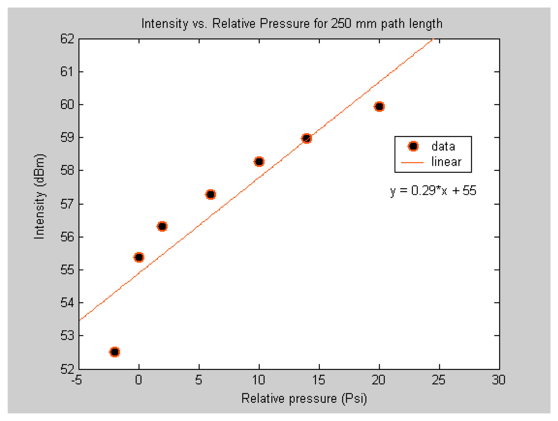
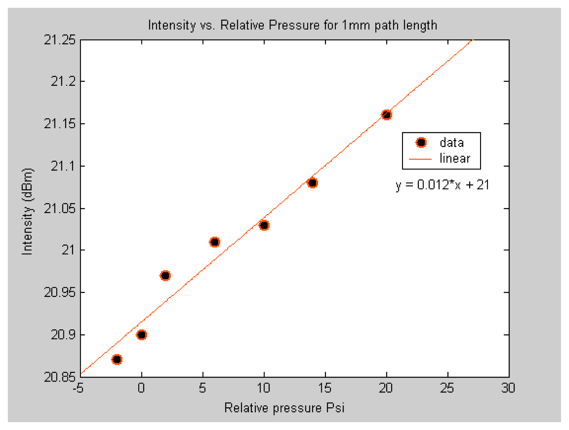
To compare the sensitivity of the sub-nL volume sensor to the μL volume sensor, the response of the two sensors to different levels of applied pressure of acetylene was investigated. This was done by fabricating two sensors. One with 3.5 μL volume gas cell and another with 0.5 nL volume gas cell. It should be noted that the two sensors are made of the same material and have similar structures. The major difference between the two is the gas cell volume. As expected from
equation 1, the results shown in
figure 6 and
figure 7 demonstrate that the two sensors response in similar manner but the magnitude of the response is not the same. The objective here is to demonstrate that the sub-nL volume sensor is capable of detecting different concentrations of acetylene. It should be noted that the sensor was also capable of detecting low concentrations as shown by the data point below zero relative pressure.
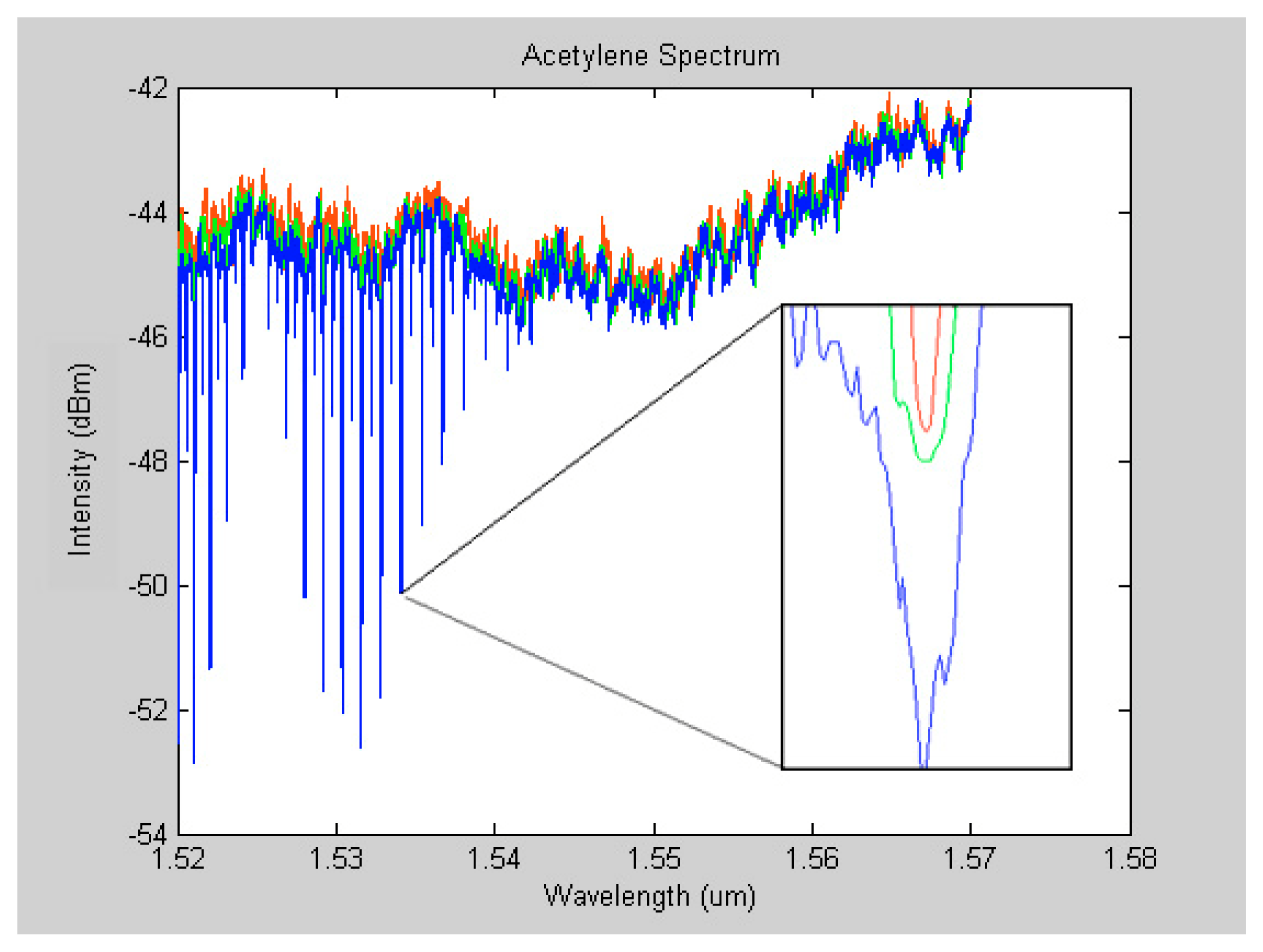
Moreover, pressure broadening effect was observed when the spectra of different pressure levels were superimposed. Zooming in at any of the absorption lines reveals the pressure broadening effect. The broadening of absorption lines in a spectrum occurs as a result of collisions between excited molecules [
23]. Pressure broadening, also known as collision broadening, is demonstrated in
figure 8. In this figure, the red, green and blue lines represent spectra at pressure levels: below atmospheric pressure, at atmospheric pressure, and 5 Psi respectively.
If we ignore all other broadening mechanisms, the absorption lines have natural width. The line width of an absorption line in a spectrum is governed by the Heisenberg uncertainty principle.
where
c is the speed of light and Δ
t is the lifetime of the excited state. However, natural broadening is not considered in the determination of the width of the lines. Only, Doppler, collision broadening or their combination is considered in line width calculations. The Doppler Effect occurs due to the direction of motion of individual molecules with respect to the light passing through it. Doppler broadening varies with temperature and molecular weight but it is independent of pressure. On the other hand, collision broadening is linearly proportional to the pressure. Collision broadening determines the profile of the absorption line when the gas present is at certain pressure level. The half-width pressure broadening is given by
where
p is the pressure and
Linewidthatmoshere is the half-width at 1 atmospheric pressure [
24]. The pressure broadening effect observed in
figure 8 could be valuable since it gives information about the pressure of the detected gas.
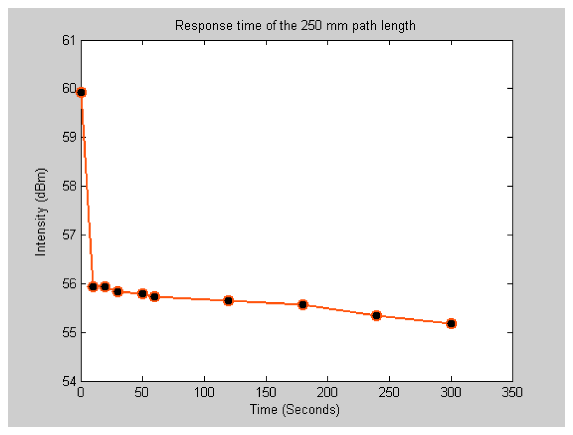
To compare the response time of the SNSC sensor to the μL volume sensor, the time required for the acetylene gas to diffuse out of the gas cell for the two sensors was measured. The decay curves shown in
figures 9 and
10 correspond to the response time of the μL and sub-nL sensors respectively. The response time measurement is limited by the time required to open the gas valve and acquire the transmission signal. It takes at least 10 seconds for the operator to open the valve and start taking snap shots of the spectrum. It appears as the sensor has almost instantaneous response to change in concentration. The absorption line intensity drops sharply as soon as the gas starts to flow out of the gas cell. Since the gas is under pressure, the flow rate decays exponentially with time as the pressure in the gas cell gets equalized.
The minimum detectable concentration can be derived by manipulating
equation 1 and is written as
where
Cmin is the minimum detectable concentration,
Io is the incident light intensity,
I is the detected light intensity,
l is the optical path length, and
ε is a constant that depends on the absorptivity of the species at a particular wavelength.
Equation 5 reveals that the detection limit is determined by the path length and the S/N ratio in the spectrum. Since only lines above the noise level in a spectrum can be detected, the reduction of noise can directly correspond to an increase in the detectability. The noise level is a function of the detector, number of scans, spectral resolution and source intensity. The interrogation system used in this work has an extremely low-noise laser source and can resolve wavelengths down to 0.25 pm. Thus, the system should produce a very low noise level. Additional noise reduction could be accomplished by using longer measurement time. This was done by setting the system to sweep across the spectrum at a rate of 0.5 Hz instead of default 5 Hz scan rate.
By using the high-resolution interrogation system a detectable intensity change as small as 0.01 dBm can be observed. For the μL volume sensor (250mm path length) and assuming
ε = 0.725 cm
-1 for acetylene, the minimum detectable concentration is less than 10 ppm. For the SNSC sensor, the minimum detectable concentration is around 1000 ppm. For reference, the standard minimum detection limit as reported in [
25] for acetylene in a 100 m path length measured in air is 0.15 ppm.
