Modelling the Transport and Kinetics of Electroenzymes at the Electrode/Solution Interface

Physical and Materials Electrochemistry Laboratory, School of Chemistry, University of Dublin, Trinity College, Dublin 2, Ireland
Sensors 2006, 6(12), 1765-1790; https://doi.org/10.3390/s6121765
Submission received: 21 September 2006
/
Revised: 1 January 2006
/
Accepted: 18 December 2006
/
Published: 19 December 2006
Abstract
:The solution phase transport and direct electrode kinetics of electro-enzymes are described in terms of a simple model in which the steady state reaction/diffusion equation for enzyme is solved subject to physically realistic boundary conditions. Two physically realizable situations are described: the semi infinite and the membrane bounded case. Limiting expressions for the reaction flux are derived and the kinetic possibilities discussed geometrically in terms of kinetic case diagrams.
Introduction
Bioelectronics is a rapidly growing field at the junction of chemistry, biochemistry and physics [1,2,3,4,5,6,7,8,9]. The ‘bottom up’ development of new biosensors is one of the principal components of this emergent subject area. A biosensor device combines the exquisite selectivity of biology with the processing power of modern microelectronics to offer powerful new analytical tools with major applications in medicine, environmental diagnostics and in the food and processing industries. Biosensors consist of a biological receptor microstructure in which there is a specific molecular interaction between the receptor and the target analyte species (the substrate). This receptor structure is coupled to an electronic transducer which converts the chemical/biochemical activity into electrical signals which can be amplified, stored, displayed and manipulated.
In the present paper we focus attention on amperometric biosensor systems which utilize redox enzymes such as the flavoprotein glucose oxidase (β-D-glucose:oxygen 1-oxido-reductase, EC 1.1.3.4) [10,11]. The redox centers of many enzymes are electrically insulated by thick protein or glycoprotein shells which serve to prevent direct electrical communication between the redox center of the enzyme and the detector electrode during amperometric detection. For enzymes such as glucose oxidase with buried redox centers, diffusing redox mediators such as ferrocene/ferricinium derivatives and the O2/H2O2 redox pair have been used to shuttle electrons between the enzyme redox site and the detector electrode. This methodology has received considerable attention.
However the direct non-diffusive mediation between a buried redox site and an electrode is also attractive because of the inherent simplicity associated with the configuration. Consequently, in the present paper we examine the situation where the redox enzyme is chemically modified by covalent attachment of an electron relay species R to the outer protein sheath (figure 1) via long and flexible spacer chains. The relay groups are distributed randomly over the outer surface of the protein sheath. In this way the enzyme is made directly electroactive, and can communicate electrically with the detector electrode. The latter is termed an electroenzyme.
Figure 1.
Schematic representation of ‘electro-enzymes’ indicating how tethered redox mediators can exchange electrons with the enzyme catalytic site buried within the protein sheath. This electron transfer may occur via unimolecular intramolecular or via bimolecular intermolecular mechanisms as indicated.
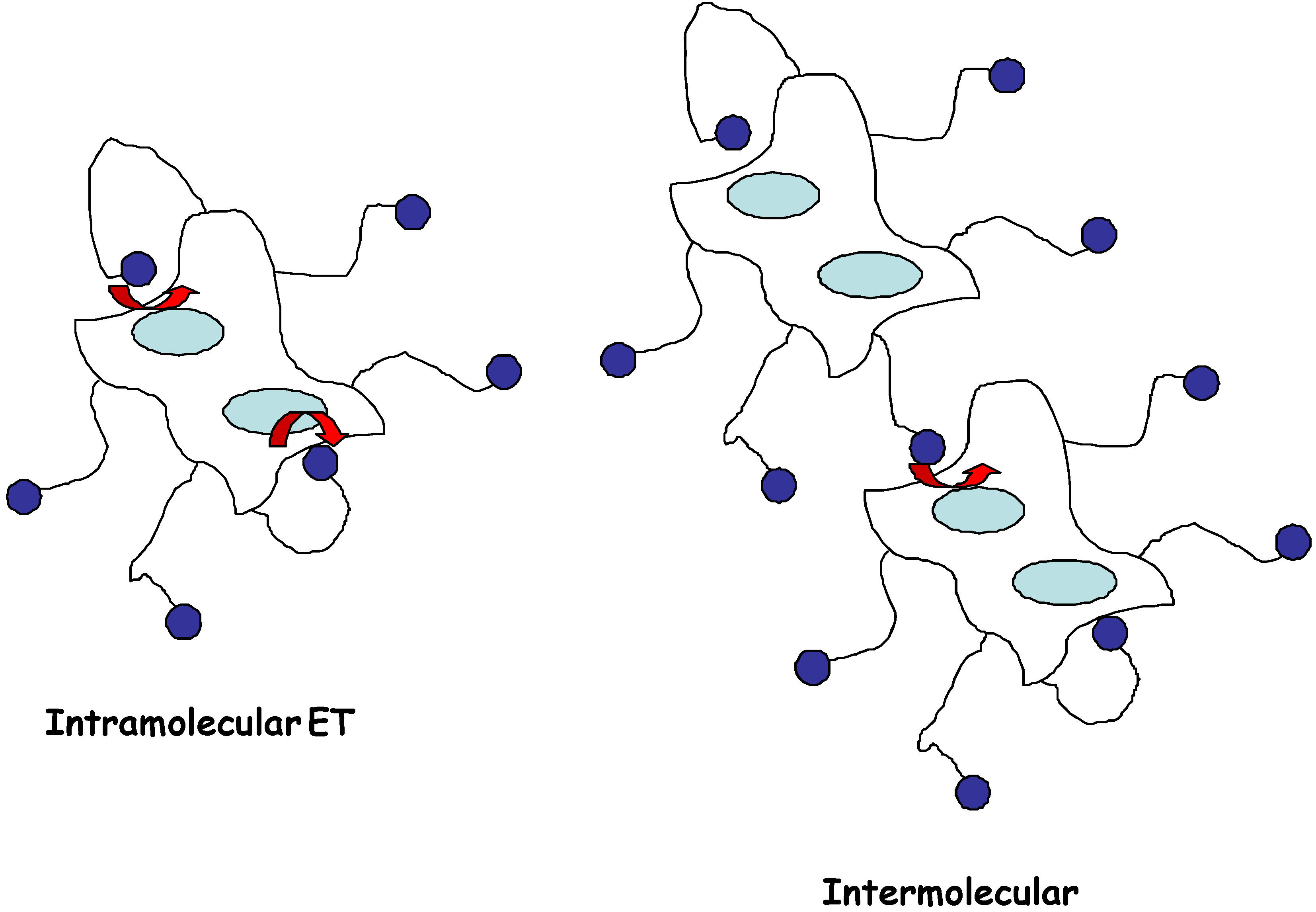
Substituted ferrocenes have been attached via flexible spacers of various lengths to glucose oxidase [12,13], and the attached mediator species is believed to act as electronic ‘stepping stones’, allowing electrons to be transferred from the flavin site to the electrode in several short steps, instead of one large step. It has been shown [12] that the length of the spacer chain is of considerable importance in determining the efficiency of electronic communication between relay site and redox site and between the relay site and the detector electrode surface. Communication is effective when the chains are long (> 10 bonds) but not when the chains are short (< 5 bonds). A peripherally attached redox mediator may accept electrons through either a unimolecular intramolecular or a bimolecular intermolecular process. The unimolecular intramolecular mechanism has been shown to predominate when the relay site is attached to the redox enzyme via long flexible spacer chains.
The chemical modification of redox proteins with synthetic electron transfer mediators is always accompanied by the partial degradation of the native biocatalyst. Furthermore, the effectiveness of the electrical contact is enhanced on increasing the mediator loading on the protein surface since electron transfer distances are thereby shortened. For glucose oxidase for example the optimum ET mediator loading is 12-13 ferrocene units per enzyme molecule [13]. However the rate constant for ET between the FAD site and the nearest electron relay group is ca. 0.9 s-1 which is much lower than that recorded for ET to the native di-oxygen acceptor (typically 5 × 10³ s-1) [11].
In the present paper we present a simple mathematical model which will describe the transport and reaction kinetics of electroenzymes at the electrode/solution interface. The pertinent reaction/diffusion equations will be developed and solved analytically to provide approximate expressions for the steady state amperometric response [14,15].
Direct reaction of redox enzymes at electrodes
We consider the following kinetic model:
where the enzyme/substrate reaction occurs in solution and is described in terms of the well known Michaelis-Menten kinetic mechanism involving formation of intermediate adduct species:
Note that the pseudo first order rate constant kE describing the reaction between the substrate and the catalytically active oxidised form of the enzyme is given by [13,14,15]:
where s∞ denotes the bulk substrate concentration and the Michaelis constant KM and catalytic rate conctant kc are defined in terms of the internal state rate constants for the elementary reaction steps as follows [16,17,18]:
where we note that . Hence the kinetics are described in terms of a specific binding interaction between the oxidised form of the redox enzyme Eox and the substrate S to form one or more distinct adduct complexes EoxS and EredP which subsequently decompose to generate the reduced form of the enzyme Ered and the product P.
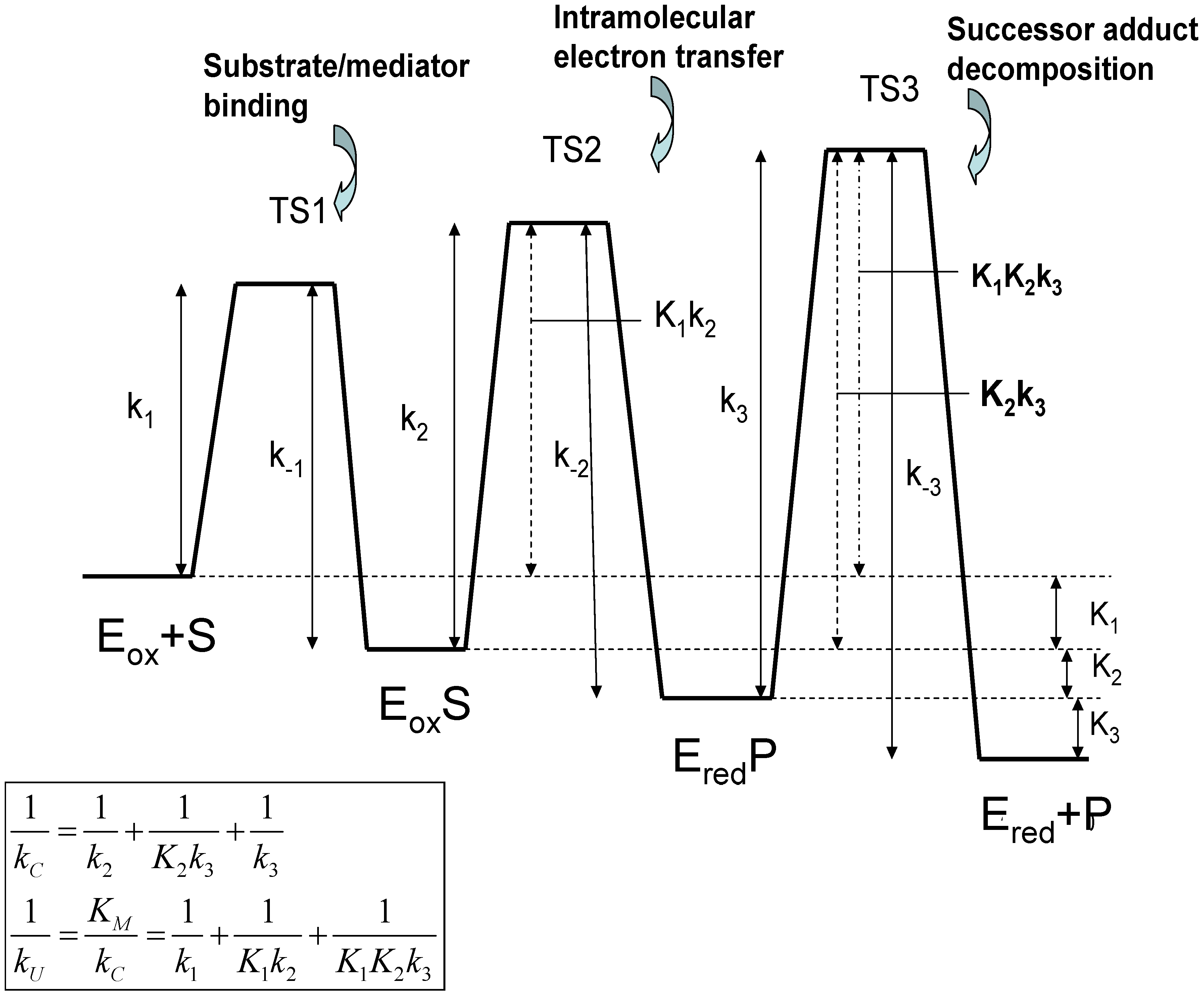
The significance of these equations have been discussed by Albery and Knowles [17]. Note that the quantity which has the dimensions of a bimolecular rate constant, provides a measure of the rate of capture of the substrate species by the oxidized enzyme Eox to form the adduct EoxS. The terms Michaelis constant and catalytic rate constant are well established in the field of enzyme kinetics [18]. The Michaelis constant KM provides a measure of the binding affinity or adduct formation ability of the substrate species for the catalytic enzyme. Alternatively, it defines the maximum value of the substrate concentration for which the catalytic kinetics are first order with respect to substrate concentration. The catalytic rate constant kC is a first order rate constant, quantifying the rate of decomposition of the surface adduct species to form product. We note from eqn.2 that both kU and kC are composite quantities, and may be considered to be internal parameters. Both quantities, when expressed in reciprocal format, consist of three separated terms. Considering the kC component terms first, we note that relates to slow rate determining intramolecular electron transfer involving the transformation of the precursor adduct EoxS to the successor adduct EredP. The term corresponds to the case where the precursor/successor adduct transformation is at a pre-equilibrium followed by a slow rate determining decomposition of the successor adduct to form products. Finally the term relates to slow rate determining successor adduct decomposition. The smallest of these terms will be the major contributor to the net catalytic rate constant kC. Similarly, if we examine the kU component terms we note that the term reflects rate determining adduct formation involving the bimolecular reaction between S and Eox. The second and third terms involve either single (K1) or multiple (K1K2) pre-equilibria followed by slow intramolecular electron transfer between the adducts EoxS and EredP within the interface region (k2) or slow successor adduct dissociation (k3). A schematic free energy profile illustrating the free energy differences associated with each of the possible rate limiting steps associated with the internal parameters is presented in figure 2.
Development of the mathematical model
The distinguishing characteristic of the direct enzyme reaction model is that the reduced form of the enzyme is transformed at the detector electrode back to the catalytically active form. The kinetics of the latter transformation is described by the electrochemical rate constant k’ET. The latter again is a composite quantity and contains contributions arising from the relay/reduced site reaction () and the relay/detector electrode interaction () with .
We assume that the enzyme concentration is much less than the substrate concentration and so we can neglect concentration polarization (i.e. diffusion) of substrate in the solution adjacent to the detector electrode. We set the total enzyme concentration as , where a and b denote the concentrations of oxidized and reduced enzyme respectively. We do however need to examine the diffusion of the oxidized form of the enzyme in solution, its reaction with the substrate, and also the heterogeneous ET kinetics of the reduced form of the enzyme at the electrode surface to regenerate the oxidized form of the enzyme.
Figure 2.
Free Energy profiles for the Michaelis-Menten adduct formation mechanism in which a substrate S binds to a catalytically active oxidized form of the enzyme Eox to form a precursor adduct species EoxS. This binding process is followed by intramolecular electron transfer in which the successor adduct species EredP is formed, which subsequently decomposes to yield the product P and non catalytically active reduced form of the enzyme Ered.

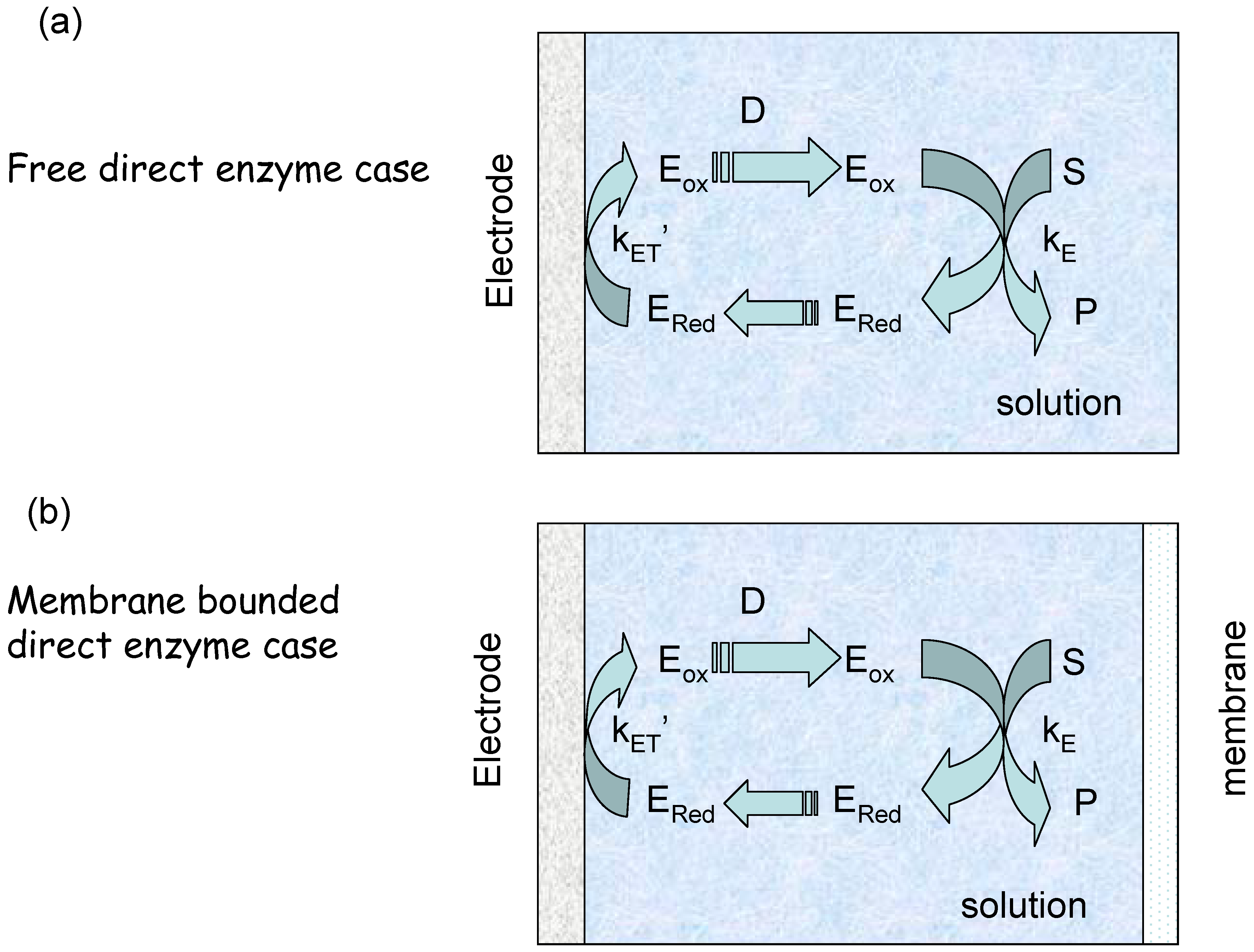
We can envisage two experimental configurations [19]. The first we denote the ‘membrane free’ situation in which the enzyme diffuses freely in solution next to the electrode (figure 3(a)). The second is designated the membrane bound situation where the enzyme and substrate are located in a thin layer of solution behind a membrane (figure 3(b)). We will consider each scenario in turn.
The membrane free situation
The net reaction flux (in units of mol cm-2 s-1) is given by:
We introduce the following non-dimensional distance and concentration variables:
where δ denotes either the diffusion layer thickness (for the membrane free situation) or the thickness of the solution layer behind the membrane (for the membrane bound system).
Figure 3.
Schematic representation of electro-enzyme transport and kinetics. (a) Free semi infinite enzyme diffusion and reaction. (b) Membrane bounded enzyme reaction and diffusion.
Figure 3.
Schematic representation of electro-enzyme transport and kinetics. (a) Free semi infinite enzyme diffusion and reaction. (b) Membrane bounded enzyme reaction and diffusion.
The transport and kinetics of the reduced enzyme under steady state conditions is described by the following reaction/diffusion equation:
where we set and defines a pseudo first order rate constant, and s denotes the substrate concentration. We also set D as the diffusion coefficient of the enzyme and assume that the diffusion coefficient of reduced and oxidized forms of the rate constant are equal. Making use of the definitions provided in eqn.4 we can transform eqn.5 into non-dimensional form as follows:
where is a parameter which compares the transit time for crossing the diffusion layer with the homogeneous rate constant describing the facility of the enzyme/substrate reaction kinetics. We note that where the reaction layer thickness provides a measure of how far the oxidized enzyme can travel before it reacts with substrate. The differential equation outlined in eqn.6 may be integrated by making use of two boundary conditions. The first concerns the situation at the detector electrode/solution interface at x = 0. Here we may write that:
or expressed in non-dimensional terms as at :
where we have written and the diffusive rate constant kD is given by . The parameter κ compares the rate of reduced enzyme reaction at the electrode surface to that of reduced enzyme diffusion to the electrode surface. Furthermore we assume that the substrate S is present in excess in the bulk of solution and so all enzyme is present in its reduced form there and so a = 0 at x = δ. This condition will be valid if oxygen is absent from the solution. Hence the boundary condition at the electrode surface is:
Now solving eqn.5 subject to eqn.8 and eqn.9 we obtain the following expression for the normalized concentration of oxidized enzyme adjacent to the electrode surface:
where
From the latter expression we can derive the normalized flux:
and so
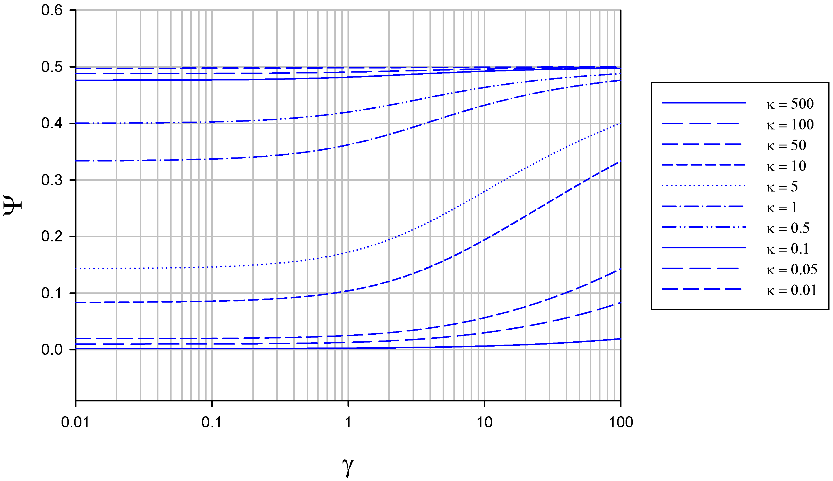
The variation of normalized flux Ψ with γ at constant κ is presented in figure 4.
Figure 4.
Variation of normalized flux Ψ with reaction/diffusion parameter γ for various fixed values of the parameter κ. The curves were calculated using eqn.13 in the text.
Figure 4.
Variation of normalized flux Ψ with reaction/diffusion parameter γ for various fixed values of the parameter κ. The curves were calculated using eqn.13 in the text.

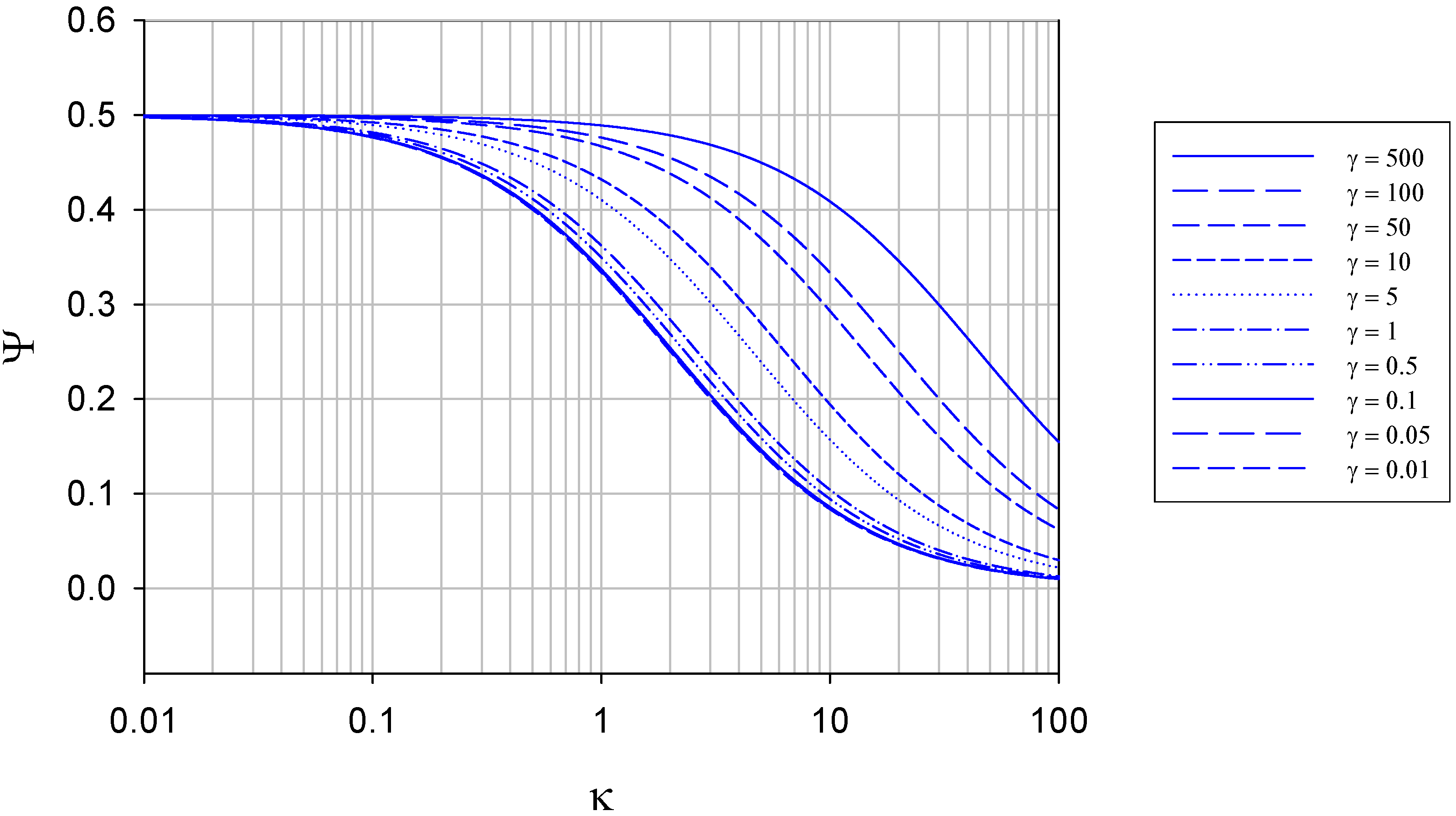
We note that eqn.13 defines the expression for the normalized flux under conditions where semi-infinite diffusion conditions pertain. In contrast, the variation of normalized flux Ψ with κ at constant γ is presented in figure 5.
Figure 5.
Variation of normalized flux Ψ with reaction/diffusion parameter κ for various fixed values of the parameter γ. The curves were calculated using eqn.13 in the text.
Figure 5.
Variation of normalized flux Ψ with reaction/diffusion parameter κ for various fixed values of the parameter γ. The curves were calculated using eqn.13 in the text.

It is interesting to note that the maximum normalized flux attained at low κ values (corresponding to slow direct enzyme regeneration at the detector electrode surface) is only 0.5, and drops to values lower than this as the rate of enzyme diffusion in the solution increases. This means that much of the reduced enzyme present in the diffusion layer after reaction with the substrate can diffuse away from the electrode into the solution bulk rather than diffuse to the electrode and be regenerated. As noted later if a membrane is present this does not happen and practically all of the reduced enzyme present in the diffusion layer will be regenerated at the electrode surface (figure 7).
We can consider two limiting cases of eqn.13 as follows. The first is when Then and the normalized flux reduces to:
In contrast when then and we obtain
Hence we note that the parameters γ and κ can be used as defining axes in the construction of a kinetic case diagram. We consider the following limiting situations. First when , we get two cases depending on the value of the parameter which compares the flux of reduced enzyme oxidation at the electrode/solution interface to the diffusive flux of reduced enzyme to the electrode surface. When , and when and . This situation corresponds to slow rate determining heterogeneous enzyme oxidation kinetics at the electrode surface. We label this as case I, and the net flux is:
Hence under these circumstances the net flux is first order in enzyme concentration and zero order with respect to substrate concentration. The flux may also depend on applied electrode potential via the term.
In contrast when the parameter then and the flux reduces to . We label this as case II and the net flux is given by:
Here the diffusion of the electroactive reduced form of the enzyme to the electrode surface is rate determining.
Second, when , the normalized flux is given by eqn.15. Again we have two limiting situations depending on the magnitude of the product . Firstly, when then and we regain case I corresponding to rate determining electrode kinetics of enzyme regeneration. In contrast, when the normalized flux reduces to which we label case III. Here the flux expression becomes:
Now we recall that and so eqn.18 reduces to:
In this case we predict that the reaction flux is first order with respect to enzyme concentration. However the reaction order with respect to substrate concentration depends on the balance between the magnitude of s and the value of the Michaelis constant KM. When s << KM we define case IIIA and eqn.19 reduces to:
and the reaction flux will be half order with respect to substrate concentration and first order with respect to enzyme concentration. In contrast at higher substrate concentrations when s >> KM then the reaction flux reduces to:
and the flux is independent of substrate concentration and first order in enzyme concentration.
Returning to eqn.20 we note that and inverting we obtain:
and we predict that a plot of versus s-1 should be linear with a slope given by and an intercept given by . The expression represents a modified form of a Lineweaver-Burk plot. An analysis based on the latter equation has been reported by Bartlett and co-workers [13]. In this work glucose oxidase was modified by the covalent attachment of ferrocene based mediators (ferrocene carboxylic acid, ferrocene acetic acid and ferrocene butanoic acid). The voltammetric response for each of these electroenzymes was obtained and a well defined voltammogram observed in each case. Bartlett and co-workers [13] estimated values for kC and KM for each of the modified enzymes from an analysis using eqn.22. Their results are presented in Table 1. The analysis using eqn.22 was replicated over a range of enzyme concentrations and the linearity predicted from the equation confirmed for all modified enzyme systems studied. The largest error was observed for low glucose concentrations, but the linearity exhibited by a typical plot (as that outlined in figure 2 of reference 13) was very good and therefore is supportive of the theory.
The membrane bounded situation
We now move to the situation where a membrane is used to enclose a thin layer of solution next to the detector electrode and re-examine the reaction-diffusion expression outlined in eqn.6 but now substitute a new boundary condition at the enzyme solution /boundary membrane interface at . Hence eqn.9 is replaced by a zero flux condition which reads:
Hence integration of eqn.6 subject to eqn.8 and eqn.23 we obtain the following expression for the normalized concentration of oxidized enzyme adjacent to the electrode surface:

| Enzyme modfier | ||||
| Glucose Oxidase | Ferrocene carboxylic acid | Ferrocene Acetic acid | Ferrocene Butanoic acid | |
| E1/2 V(vs SCE) | - ca. 0.41 | 0.3- 0.33 | 0.13-0.18 | 0.09-0.11 |
| # ferrocene per enzyme | 2 | 13 | 22 | 29 |
| kC/s-1 | 800 | 5 | 1100 | 50 |
| KM/mM | 20 | 1 | 5 | 2 |
| kU = kC/KM dm3mol-1s-1 | 40 × 103 | 5 × 10³ | 220 × 103 | 25 × 103 |
1 Data obtained in author’s laboratory from analysis of cyclic voltammetry data of GOxadsorbed on carbon electrodes modified with a mesh of single walled carbon nanotubes in phosphate buffer pH 7.
The concentration of reduced enzyme is given by . Specifically at and we write:
and we can immediately write the expression for the normalized reaction flux by noting that:
The variation of Ψ with γ and κ computed from eqn.26 is outlined in figure 6 and figure 7. In figure 6 the variation of normalized flux Ψ with reaction/diffusion parameter γ for various set values of the parameter κ is illustrated.
Figure 6.
Variation of normalized flux Ψ with reaction/diffusion parameter γ for various fixed values of the parameter κ. The curves were calculated using eqn.26 in the text.
Figure 6.
Variation of normalized flux Ψ with reaction/diffusion parameter γ for various fixed values of the parameter κ. The curves were calculated using eqn.26 in the text.
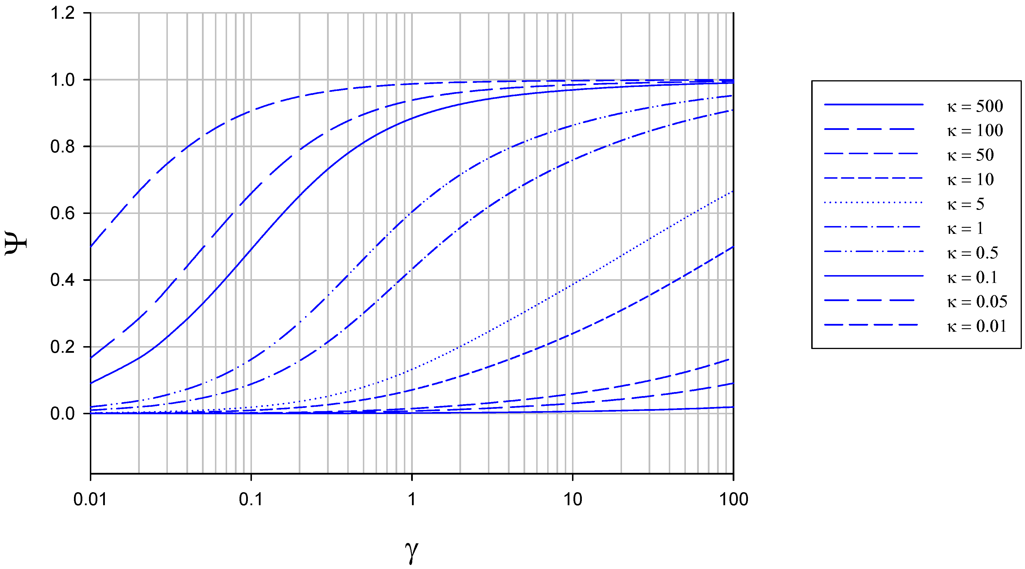
We note that the normalized flux increases in a regular manner with increasing γ value for all values of κ chosen, reaching a maximum value of Ψ = 1 when the value of γ is large. As κ decreases Ψ increases to attain its limiting value close to unity at a lower value of γ. This trend is more explicitly illustrated in figure 7. Now and so the current response will be close to its maximum value characteristic of direct reaction at the electrode surface when the parameter κ is smallest. This occurs when the enzyme regeneration kinetics is much slower than that of reduced enzyme diffusion.
Again we can deconstruct eqn.26 by taking suitable limiting approximations. For instance when the reaction/diffusion parameter γ is small then and eqn.26 reduces to:
Alternatively when γ is large then and eqn.26 reduces to:
which is the same as eqn.15 obtained for the membrane free case.
Figure 7.
Variation of normalized flux Ψ with reaction/diffusion parameter κ for various fixed values of the parameter γ. The curves were calculated using eqn.26 in the text.
Figure 7.
Variation of normalized flux Ψ with reaction/diffusion parameter κ for various fixed values of the parameter γ. The curves were calculated using eqn.26 in the text.

Again looking at eqn.27, when we get two limiting cases depending on whether . First if then . We recall that the former parameter compares the flux of reduced enzyme oxidation at the electrode to the diffusive flux of reduced enzyme to the site of re-oxidation () whereas the latter parameter compares the flux for the homogeneous enzyme/substrate kinetics to the transit time for enzyme diffusion across the solution layer (). Hence the product compares the flux of reduced enzyme oxidation at the detector electrode surface to the flux arising from the bimolecular homogeneous enzyme/substrate reaction within the diffusion layer. Consequently when then and the regeneration of oxidized enzyme is slow and rate determining. Under such circumstances the normalized flux reduces to or:
which again is case I met previously for the membrane free situation. The current flow depends only on the concentration of enzyme, may exhibit a potential dependence and will be independent of substrate concentration. Conversely when then and . Here oxidized enzyme regeneration is fast and the Michaelis-Menten enzyme/substrate kinetics is slow and rate determining. Here the normalized flux reduces to and the net reaction flux is given by
We label this situation as case IV. In this case the flux will depend on substrate concentration according to the Michaelis-Menten rate law but will also depend on the thickness of the solution layer trapped behind the membrane, When s << KM we have and we have case IVa corresponding to unsaturated enzyme kinetics. In contrast, when KM << s then , we have case IVb and we have saturated enzyme kinetics. More generally, inversion of eqn.29 yields
and a plot of versus is linear with a slope given by and intercept .
The situation for large γ yields eqn.15 previously obtained for the semi-infinite situation. Again we have two limiting cases depending on the magnitude of the product . Firstly, when then and we regain case I corresponding to rate determining electrode kinetics of enzyme regeneration. In contrast, when the normalized flux reduces to which we have labeled case III.
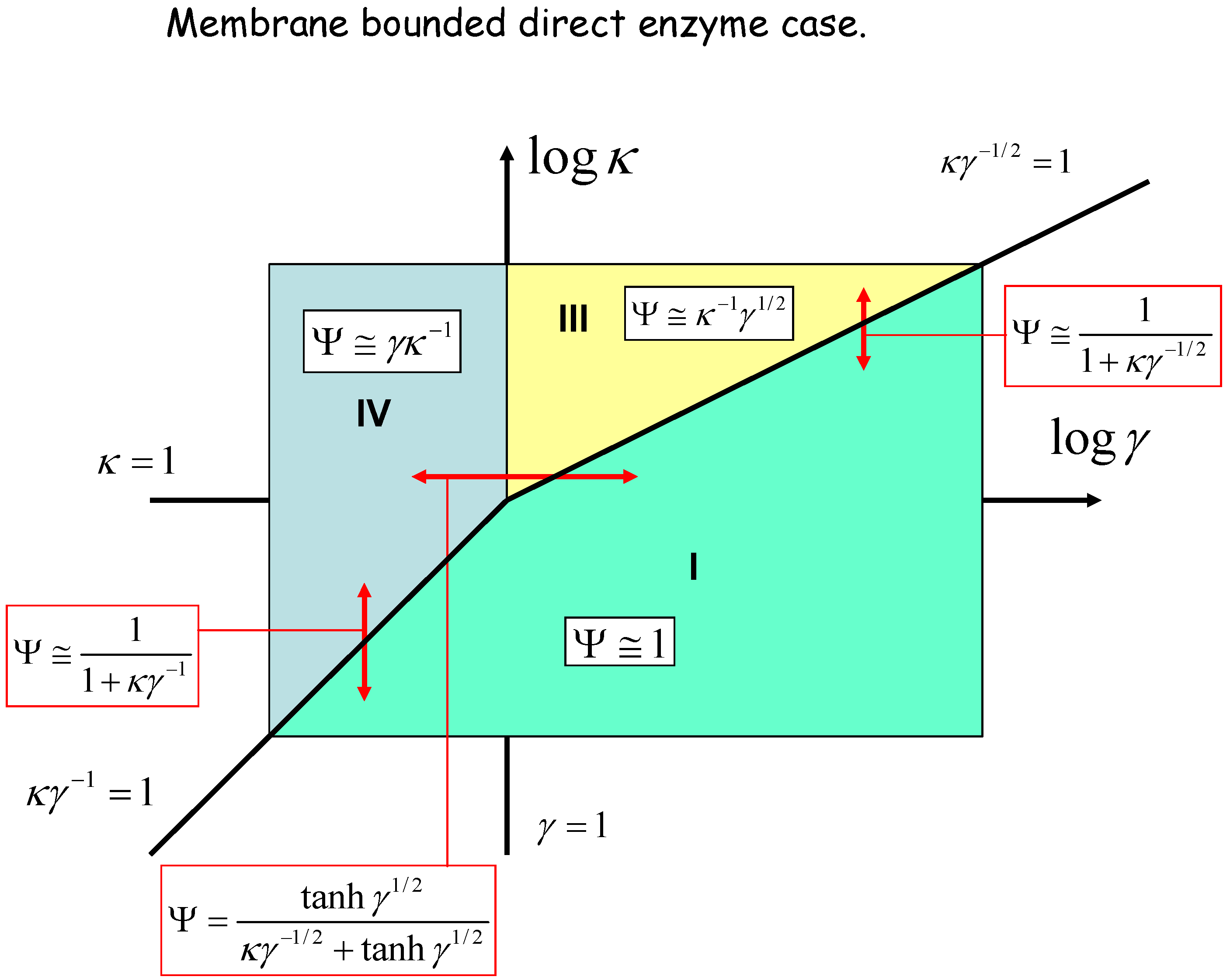
We can geometrically represent the analysis in terms of a kinetic case diagram. This is presented in figure 8 and figure 9. The natural axes defining the case diagram are log κ and log γ. The membrane free direct enzyme case is outlined in fig.8 whereas the membrane bound situation is presented in fig.9.
Figure 8.
Kinetic case diagram (plot of log κ versus log γ) for membrane free direct reaction and diffusion of electro-enzyme. Note that κ compares the rate of enzyme regeneration at the electrode with that of enzyme diffusion through the solution, whereas γ compares the rate of enzyme diffusion to that of homogeneous reaction between enzyme and substrate. In both cases approximate limiting expressions for the normalized flux and the expressions delineating the boundaries between specific cases are presented.
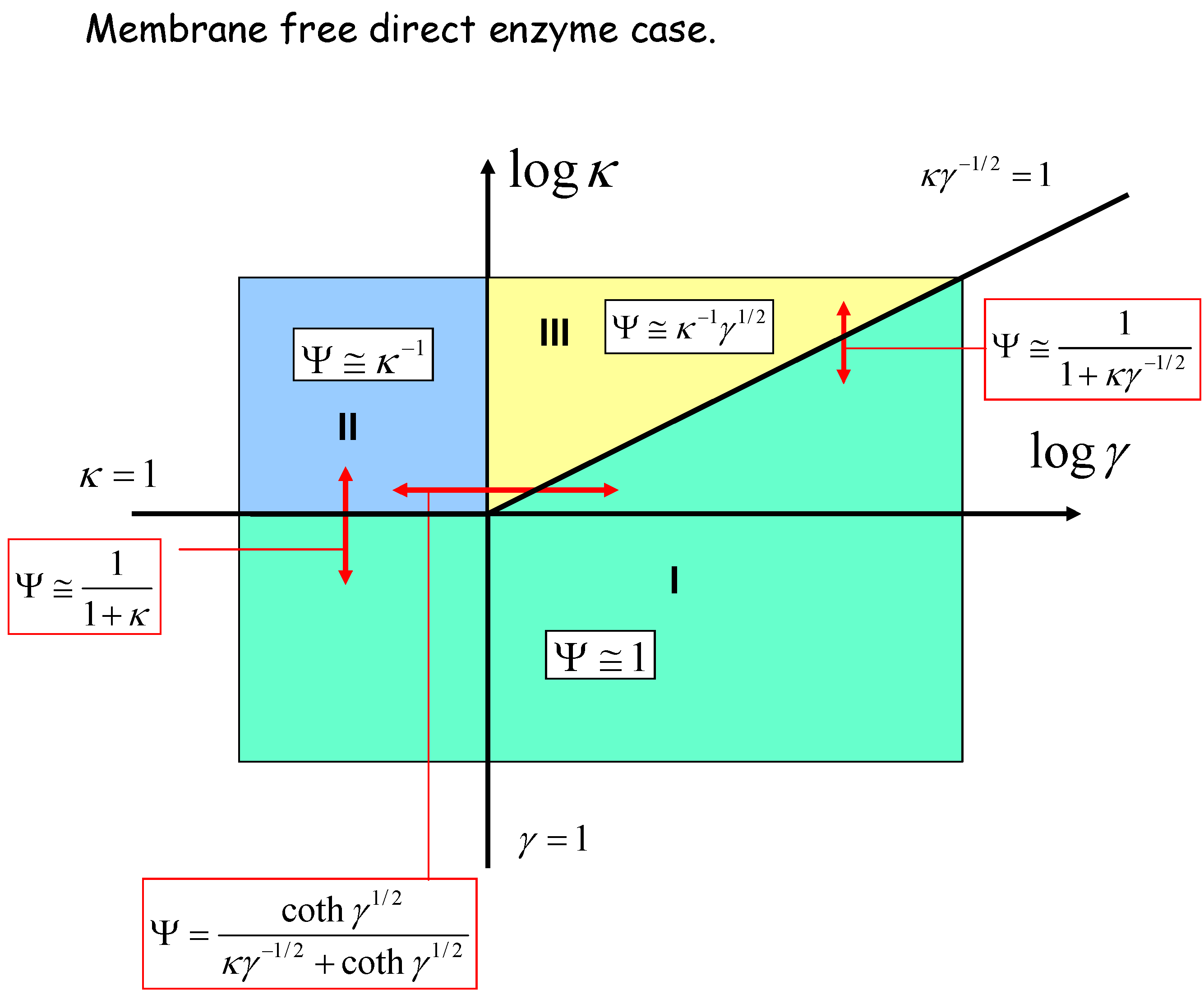
Figure 9.
Kinetic case diagram (plot of log κ versus log γ) for membrane bound direct reaction and diffusion of electro-enzyme. Note that κ compares the rate of enzyme regeneration at the electrode with that of enzyme diffusion through the solution, whereas γ compares the rate of enzyme diffusion to that of homogeneous reaction between enzyme and substrate. In both cases approximate limiting expressions for the normalized flux and the expressions delineating the boundaries between specific cases are presented.

Three kinetic sub-cases (I, II and III) are relevant for the semi-infinite membrane free situation. The bounded membrane situation is well described by the sub-cases labeled I, III and IV. Common to both are cases I and III. Case II is found only in the semi-infinite membrane free case whereas case IV is specific to the membrane bound situation. In fig.8 the II/III case boundary lies at γ = 1, the I/II boundary is at κ = 1, and the I/III boundary is set at κγ-1/2 = 1. In fig.9 we note that the I/III boundary is again defined by the line κγ-1/2 = 1, whereas the I/IV boundary is defined by the line κγ-1 = 1. The III/IV boundary is γ = 1.
We can directly compare the amperometric response obtained for the membrane free situation compared with that obtained for the membrane bound situation by taking the ratio of the normalized fluxes:
This ratio is illustrated schematically in figure 10 for various values of the parameters κ and γ.
Figure 10.
The ratio of the amperometric response obtained for the membrane free configuration to that corresponding to the membrane bound situation as a function of the normalized parameter γ which compares the rate of enzyme diffusion in the solution region next to the detector electrode with the rate describing the reaction between enzyme and substrate in the solution. The flux ratio is presented also for various values of the parameter κ which compares the rate of the reduced enzyme reaction at the detector electrode surface to that of reduced enzyme diffusion to the electrode surface.
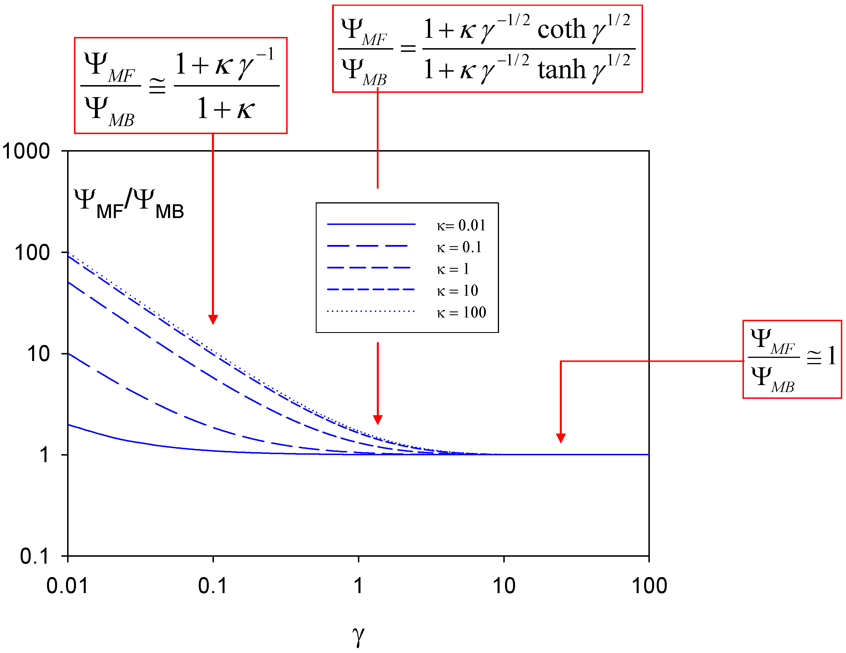
We note from figure 10 that for all values of κ . Furthermore the ratio increases significantly as γ decreases. The rate of increase in the latter ratio with decreasing γ value is more marked for lower values of the parameter κ. In short the steady state amperometric response expected for a sensor which does not have a bounding membrane coating is significantly larger than that recorded for a sensor containing a membrane when the homogeneous enzyme/substrate reaction kinetics is slower compared to the rate of diffusive movement of enzyme across the diffusion layer and when the rate of oxidized enzyme regeneration at the electrode surface is much smaller than that of enzyme diffusion.
We summarize the kinetic results obtained for all four limiting kinetic cases in table 2 below. In all cases a distinct dependence of steady state reaction flux on experimentally measurable parameters such as enzyme concentration, substrate concentration and electrode potential is predicted.
Table 2.
Summary of pertinent rate limiting expressions for direct electro-enzyme reaction.

General comments regarding amperometric enzyme biosensor modelling
In the present communication we have presented a detailed theoretical analysis of the pertinent physical processes underlying the operation of amperometric enzyme electrodes in which the enzyme is suitably modified such that it exhibits direct electroactivity at the detector electrode surface. The mass transport and heterogeneous electron transfer kinetics of the redox enzyme were analyzed by solving the pertinent steady state reaction/diffusion equation. Two situations were examined. In the first, a semi infinite condition was adopted in which the solution next to the detector electrode is unbounded. In the second the enzyme is contained within a thin layer of solution next to the electrode surface by a bounding membrane. Analysis of both situations produced analytical expressions for the reaction flux. The latter could be further simplified into four distinct approximate expressions corresponding to various rate limiting situations. The limiting kinetic cases were subjected to geometric visualization using kinetic case diagrams. The analysis developed was particularly simple and it is constructive to compare it with previous work reported on the mathematical analysis of amperometric enzyme biosensor systems.
Much has been done in recent times in the area of mathematical modeling of amperometric enzyme electrodes. For example, there has been considerable interest in recent years in the immobilization of enzymes within electronically conducting and redox conducting polymer films. Electrochemical polymerization provides a simple and attractive approach for the immobilization of enzymes at electrode surfaces. The process can be controlled by the choice of electrode potential and will therefore allow accurate control of the polymer film thickness and hence the amount of enzyme entrapped in close proximity to the electrode surface. Progress in this area has been outlined in the recent reviews of Bartlett and Cooper [20], and Chaubrey and co-workers [21,22]. The kinetics of immobilized enzymes dispersed in polymer films of appreciable thickness has been reported by Mell and Maloy [23] Bartlett and Whittaker [24,25], Gooding and co-workers [26] Marchesiello and Genies [27], Bartlett and Pratt [28], Karube and co-workers [29] and Matsumoto et al [30].
The kinetic analysis of a dispersed enzyme configuration within a porous polymer layer is complex. The reaction scheme envisaged is as follows:
where A and B denote the reduced and oxidized forms of the mediator (e.g. ferrocene/ferricinium), Eox, ERed denote the oxidized and reduced forms of the redox enzyme and S,P are the substrate and product. Again kE and kM are rate constants defining the reaction kinetics between substrate/enzyme and mediator/enzyme respectively.
Figure 11.
Schematic of a typical enzyme membrane electrode illustrating the various transport and kinetic processes which may serve as rate determining factors.
Figure 11.
Schematic of a typical enzyme membrane electrode illustrating the various transport and kinetic processes which may serve as rate determining factors.
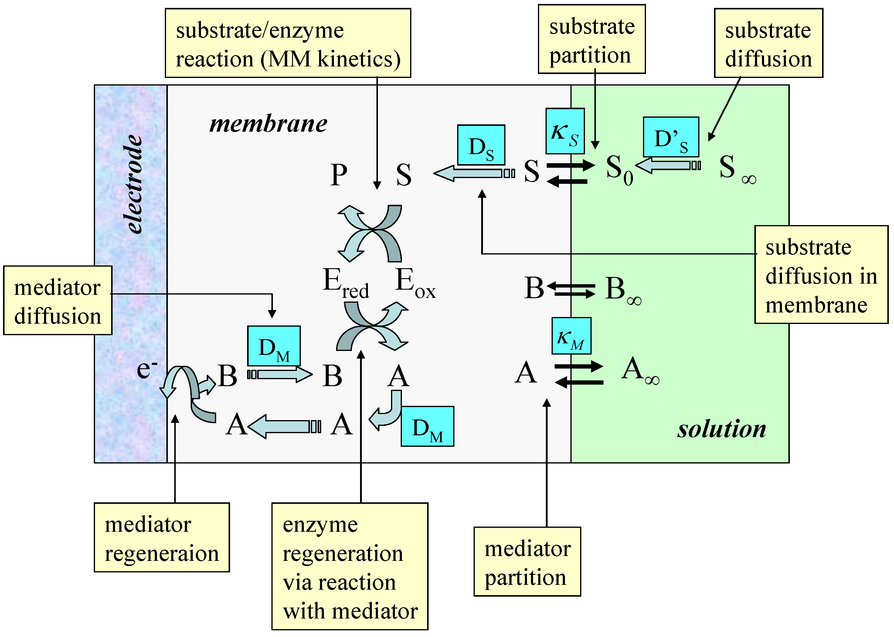
Typical processes to be modeled are outlined schematically in figure 11. The scheme is based on a redox enzyme such as glucose oxidase which follows a ‘ping-pong’ reaction mechanism. In the figure A/B represents the mediator redox couple, Eox and Ered, and S/P represent the substrate and product species respectively. We assume that the enzyme E is immobilized within the polymer matrix such that its concentration is uniform throughout the thickness L of the polymer layer. The substrate is free to diffuse through the film with a diffusion coefficient DS. It should be noted that the value of the substrate diffusion coefficient for transport within the porous matrix may differ in magnitude from that exhibited by the substrate in solution. Partitioning of the substrate across the membrane/solution interface occurs and is quantified by a partition coefficient κS. Bartlett and Pratt [28] have noted that the redox mediator may be entrapped within the enzyme layer or it may be present in both the enzyme layer and in bulk solution. Indeed the redox mediator may be present either in its oxidized form (e.g. dioxygen) or in its reduced form (e.g. ferrocene) in solution. Both situations are found in practice. It is assumed that the mediator can only be regenerated at the electrode surface giving rise to a current which can be used to monitor the catalytic sequence of reactions. Bartlett and Pratt [28] have considered in detail the former situation in which the mediator is trapped within the film. Detailed analysis produces non linear reaction diffusion equations which may only be subject to an approximate analytical solution.
One can readily show that the following reaction/diffusion equations pertain to the situation presented in figure 11.
In the latter expressions the normalized substrate and mediator concentrations are given by where b denotes the concentration of oxidized mediator, s is the substrate concentration and κS is the partition coefficient of substrate. If the mediator is contained within the membrane then , the total mediator concentration in the film. Alternatively, if the mediator is present in solution then where c∞ denotes the bulk concentration of mediator in solution and κM is the partition coefficient of mediator. Also the normalized distance is .
A number of characteristic parameters are introduced into the kinetic analysis. The first is the competition parameter . Here the parameter θ defines the balance between the mediator/enzyme kinetic flux and the substrate/enzyme kinetic flux. Since the substrate S reacts with the oxidized enzyme Eox and the mediator with the reduced enzyme ERed, the parameter θ will also define the balance between the oxidized and reduced forms of the enzyme in the film. Hence when the kinetics will be limited by the reaction between the reduced enzyme and the oxidized mediator species B. Hence under such conditions the film will mainly considt of reduced enzyme species. In contrast when the kinetics are limited by the reaction between oxidized enzyme and substrate and the film mainly consists of oxidized enzyme. We can also introduce a reaction/diffusion parameter . This is a parameter which compares the flux of the mediator/enzyme reaction with that for mediator diffusion across the film. Finally the parameters and define a mixed diffusion/reaction term and a saturation parameter respectively.
Furthermore the flux due to turnover of mediator by the substrate is balanced by the difference between the fluxes due to mediator loss at the membrane/solution interface and that due to mediator generation at the electrode/membrane interface:
In contrast the normalized flux at the electrode/membrane interface is:
Note that in general and indeed . In the latter expressions DM denotes the diffusion coefficient of the mediator in the film, L is the membrane thickness, denote the reaction flux arising from the mediator/substrate reaction and that related to the steady state current flow via the Faraday electrolysis law () respectively. Note also that c denotes the total mediator concentration. The non-linear reaction/diffusion equations expressed in eqn.79 are integrated subject to the following boundary conditions:
and
Note that the boundary conditions outlined in eqn.37 are of three types depending on the type of biosensor system utilized. The first corresponds to the case where the redox mediator is contained within the film. The second corresponds to the situation where the oxidized mediator, such as molecular oxygen, is present in the bulk solution. The third corresponds to the situation where the reduced mediator such as ferrocene carboxylic acid is present in the solution bulk. In both of the latter two cases the mediator partitions into the film from the solution and we have mediator transport across the membrane/solution interface. Finally the mediator concentration at the detector interface at χ = 0 is fixed by the value of the applied electrode potential. If for example the mediator regeneration reaction at the detector electrode is Nernstian then we can write that where the normalized potential is . Under limiting current conditions and .
Now the reaction diffusion equations presented in eqn.33 may be solved approximately for various limiting values of θ say (i.e. whether substrate limited or mediator limited kinetics). A situation may also be found in which one part of the film may exhibit mediator limited kinetics whereas another part may exhibit substrate limitation. This is the so called titration situation Furthermore the situation when the substrate concentration is uniform across the film may be addressed. This is important when the layer is thin. All of these situations may be subjected to detailed analysis along lines similar to that outlined in previous sections. This has been done by Bartlett and Pratt [28] most particularly for the situation where the mediator is confined to the thin film. Case diagrams may be constructed and limiting analytical expressions for the steady state flux derived.
Further theoretical activity associated with amperometric enzyme biosensors may be briefly mentioned here. The model depicted in figure 11 refers to the situation of heterogeneous mediation. This should be distinguished from homogeneous mediation in which the substrate, enzyme and mediator are all located within the diffusion layer adjacent to a support electrode surface. This situation has been discussed by Albery and co-workers [31] and by Bartlett and Pratt [32]. Again non-linear reaction diffusion equations may be proposed and approximately solved to yield kinetic expressions and kinetic case diagrams. The problem is very complex and has been well described in the review by Bartlett Tebbutt and Whitaker [11]. An interesting analysis of an amperometric enzyme electrode in which an artificial electron acceptor competes with oxygen for the reduction of the enzyme has been reported by Hall and Martens [33]. The topic of amperometric biosensor amplification [34,35] has also been examined. The sensitivity of enzyme electrodes can be increased substantially by incorporation of a substrate recycling scheme [36,37]. A possible strategy here involves an electrochemical recycling of enzyme substrate during the transduction step. Hence the shuttle analyte is measured not just once but is reconverted to be measured again leading to an amplification in the transduction signal. Finally the modeling of an immobilized oxidase system located in a matrix through which a distribution of conductive metallic nanoparticles of defined size has been dispersed has been reported [38,39].
In this paper we have concentrated on a particularly simple example of mathematical modeling applied to the biosensor/solution interface, that of direct enzyme reaction at surfaces. As we have seen from our brief overview of mathematical modeling approaches to understanding amperometric enzyme biosensors, the analysis presented in the present communication is the most simple that one may perform for such systems. The inherent simplicity of the direct electroenzyme reaction is also a reason why such systems are ideally to be preferred in a practical biosensor device. We conclude that the mathematical modeling of amperometric enzyme biosensors offer many and indeed varied problems of considerable challenge, and the results obtained can provide considerable insight into the mechanism of biosensor operation.
Acknowledgements
The author is grateful to the Irish National funding bodies (Higher Education Authority, Irish Research Council for Science, Engineering and Technology, Enterprise Ireland) for the receipt of funding under the following research programmes: PRTLI (Grant: HEA-PRTLI-IAMS Cycle 3) and Basic Research Scheme (Grant numbers SC/02/169 and SC/03/049).
Glossary of symbols used
| A | Geometric surface area of electrode (units: cm2). |
| a | Concentration of reduced enzyme (units: mol cm-3). |
Normalised parametet quantifying the degree of unsaturation of enzyme/substrate reaction kinetics. | |
| b | Concentration of oxidized enzyme (units: mol cm-3). |
Surface concentration of oxidized enzyme (units: mol cm-3). | |
| c | Total mediator concentration (unit: mol cm-3). |
Total mediator concentration in thin film (unit: mol cm-3). | |
Total bulk mediator concentration in solution (unit: mol cm-3). | |
| D | Enzyme diffusion coefficient (units: cm2 s-1). |
| DM | Diffusion coefficient of redox mediator (unit: cm2 s-1). |
| DS | Diffusion coefficient of substrate (unit: cm2 s-1). |
| δ | Nernst diffusion layer thickness (units: cm). |
| Eox, Ered | Oxidised and reduced forms of the redox enzyme. |
Electrode potential and standard electrode potential (units: V). | |
Total enzyme concentration (units: mol cm-3). | |
| F | Faraday Constant (96,500 C mol-1). |
Net reaction flux (rate) for direct enzyme reaction (units: mol cm-2 s-1). | |
Net reaction flux related to the steady state current flow for immobilized enzyme electrode (unit: mol cm-2 s-1). | |
Reaction flux arising from the mediator/substrate reaction (unit: mol cm-2 s-1). | |
Dimensionless parameter which compares the transit time for crossing the diffusion layer with the homogeneous rate constant describing the facility of the enzyme/substrate reaction kinetics. | |
Dimensionless parameter which compares the flux of the mediator/enzyme. reaction with that for mediator diffusion across the immobilizing film. | |
Reaction layer thickness measuring the distance the oxidized enzyme can travel before it reacts with substrate. | |
| L | Total film thickness (unit: cm). |
| n | Number of electrons transferred in reaction. |
Mixed reaction/diffusion parameter. | |
| S | Substrate or reactant species. |
| s | Substrate (reactant) concentration (units: mol cm-3). |
Bulk substrate concentration (units: mol cm-3). | |
Michaelis constant (units: mol cm-3). | |
Pseudo first order rate constant (units: s-1) for Michaelis-Menten enzyme kinetics. | |
Catalytic rate constant in Michaelis-Menten mechanism (units: s-1). | |
Diffusive rate constant for enzyme transport. | |
Heterogeneous electron transfer rate constant for direct reaction of enzyme at electrode surface (unit: cm s-1). | |
Rate constant for reaction between covalently tethered redox relay molecule and reduced enzyme active site (unit: cm s-1). | |
Rate constant for heterogeneous reaction between redox relay and detector electrode (unit: cm s-1). | |
Composite rate constant quantifying reaction between substrate and the catalytically active oxidized form of the redox enzyme. | |
Unsaturated rate constant describing bimolecular kinetics between enzyme and substrate (units: cm3 mol-1 s-1). | |
Equilibrium constant of step i related to internal processes in Michaelis-Menten adduct formation mechanism illustrated in figure 2 of the text. | |
Dimensionless parameter comparing the rate of reduced enzyme reaction at the electrode surface with that of reduced enzyme diffusion to the electrode surface. | |
Partition coefficient of substrate and mediator respectively. | |
Dimensionless substrate concentration. | |
| P | Product species. |
Dimensionless parameter which defines the balance between the mediator/enzyme kinetic flux and the substrate/enzyme kinetic flux. | |
Dimensionless concentration of reduced enzyme | |
Dimensionless concentration of reduced enzyme at electrode surface. | |
Dimensionless concentration of oxidized mediator. | |
Dimensionless concentration of oxidized mediator at electrode surface. | |
| x | Distance variable (unit: cm). |
Non dimensional distance variable. | |
Normalised electrode potential. | |
Normalised reaction flux for enzyme electrode. | |
Normalised flux arising from turnover of mediator by the substrate. | |
Normalised flux at electrode/solution interface. |
References and Notes
- Rosi, N.L.; Mirkin, C.A. Nanostructures in biodiagnostics. Chem. Rev. 2005, 105, 1547–1562. [Google Scholar] [CrossRef] [PubMed]
- Willner, I.; Willner, B.; Katz, E. Functional biosensor systems via surface nanoengineering of electronic elements. Reviews in Molecular Biotechnology 2002, 82, 325–335. [Google Scholar] [CrossRef]
- Willner, I.; Katz, E. Integration of layered redox proteins and conductive supports for bioelectronic applications. Angew Chem. Int. Ed. 2000, 39, 1180–1218. [Google Scholar] [CrossRef]
- Willner, I.; Willner, B. Biomaterials integrated with electronic elements: en route to bioelectronics. Trends in Biotechnology 2001, 19, 222–230. [Google Scholar] [CrossRef]
- Davis, J.J.; Morgan, D.A.; Wrathmell, C.L.; Axford, D.N.; Zhao, J.; Wang, N. Molecular bioelectronics. J. Mater. Chem. 2005, 15, 2160–2174. [Google Scholar] [CrossRef]
- Scheller, F.W.; Wollenberger, U.; Lei, C.; Jin, W.; Ge, B.; Lehmann, C.; Lisdat, F.; Fridman, V. Bioelectrocatalysis by redox enzymes at modified electrodes. Reviews in Molecular Biotechnology 2002, 82, 411–424. [Google Scholar] [CrossRef]
- Schuhmann, W. Amperometric enzyme biosensors based on optimized electron transfer pathways and non-manual immobilization procedures. Reviews in Molecular Biotechnology 2002, 82, 425–441. [Google Scholar] [CrossRef]
- Habermuller, K.; Mosbach, M.; Schuhmann, W. Electron transfer mechanisms in amperometric biosensors. Fresenius J. Anal. Chem. 2000, 366, 560–568. [Google Scholar] [PubMed]
- Schmidt, H.L.; Schuhmann, W. Reagentless oxidoreductase sensors. Biosensors & Bioelectronics 1996, 11, 127–135. [Google Scholar]
- Freire, R.S.; Pessoa, C.A.; Mello, L.D.; Kubota, L.T. Direct electron transfer: an approach for electrochemical biosensors with higher selectivity and sensitivity. J. Braz. Chem. Soc. 2003, 14, 230–243. [Google Scholar] [CrossRef]
- Bartlett, P.N.; Tebbutt, P.; Whitaker, R.G. Kinetic aspects of the use of modified electrodes and mediators in bioelectrochemistry. Prog. Reaction Kinetics 1991, 16, 55–155. [Google Scholar]
- Schuhmann, W.; Ohara, T.J.; Schmidt, H.L.; Heller, A. Electron transfer between glucose oxidase and electrodes via redox mediators bound with flexible chains to the enzyme surface. J. Am. Chem. Soc. 1991, 113, 1394–1397. [Google Scholar] [CrossRef]
- Bartlett, P.N.; Whitaker, R.G.; Green, M.J.; Frew, J. Covalent binding of electron relays to glucose oxidase. J. Chem. Soc., Chem. Commun. 1987, 1603–1604. [Google Scholar] [CrossRef]
- Bartlett, P.N.; Pratt, K.F.E. Modelling of processes in enzyme electrodes. Biosensors & Bioelectronics 1993, 8, 451–462. [Google Scholar]
- Lyons, M.E.G. Electrocatalysis using electroactive polymer films. In Electroactive Polymer Electrochemistry. Part 1. Fundamentals; Lyons, M.E.G., Ed.; Plenum Press: New York, 1994; Chapter 2; pp. 237–374. [Google Scholar]
- Lyons, M.E.G.; Lyons, C.H.; Michas, A.; Bartlett, P.N. Heterogeneous redox catalysis at hydrated oxide layers. J. Electroanal. Chem. 1993, 351, 245–258. [Google Scholar] [CrossRef]
- Albery, W.J.; Knowles, J.R. Evolution of enzyme function and development of catalytic efficiency. Biochemistry 1976, 15, 5631–5640. [Google Scholar] [CrossRef] [PubMed]
- Northrop, D.B. On the meaning of KM and v/KM in enzyme kinetics. J. Chem. Ed. 1998, 75, 1153–1157. [Google Scholar] [CrossRef]
- Albery, W.J.; Bartlett, P.N.; Craston, D.H. Amperometric enzyme electrodes. Part 2. Conducting salts as electrode materials for the oxidation of glucose oxidase. J. Electroanal. Chem. 1985, 194, 223–235. [Google Scholar] [CrossRef]
- Bartlett, P.N.; Cooper, J.M. A review of the immobilization of enzymes in electropolymerized films. J. Electroanal. Chem. 1993, 362, 1–12. [Google Scholar] [CrossRef]
- Gerard, M.; Chaubrey, A.; Malhotra, B.D. Applications of conducting polymers to biosensors. Biosensors & Bioelectronics 2002, 17, 345–359. [Google Scholar]
- Chaubrey, A.; Malhotra, B.D. Mediated biosensors. Biosensors & Bioelectronics. 2002, 17, 441–456. [Google Scholar]
- Mell, L.D.; Maloy, J.T. A model for the amperometric enzyme electrode obtained through digital simulation and applied to the immobilized glucose oxidase system. Anal. Chem. 1975, 47, 299–307. [Google Scholar] [CrossRef]
- Bartlett, P.N.; Whitaker, R.G. Electrochemical immobilization of enzymes. Part 1. Theory. J. Electroanal. Chem. 1987, 224, 27–35. [Google Scholar] [CrossRef]
- Bartlett, P.N.; Whitaker, R.G. Electrochemical immobilization of enzymes. Part 2. Glucose oxidase immobilized in poly-N-methyl pyrrole. J. Electroanal. Chem. 1987, 224, 37–48. [Google Scholar] [CrossRef]
- Gooding, J.J.; Hall, E.A.H.; Hibbert, D.B. From thick films to monolayer recognition layers in amperometric enzyme electrodes. Electroanalysis 1998, 10, 1130–1136. [Google Scholar] [CrossRef]
- Marchesiello, M.; Genies, E. A theoretical model for an amperometric glucose sensor using polypyrroleas an immobilization matrix. J. Electroanal. Chem. 1993, 358, 35–48. [Google Scholar] [CrossRef]
- Bartlett, P.N.; Pratt, K.F.E. Theoretical treatment of diffusion and kinetics in amperometric immobilized enzyme electrodes. Part 1. Redox mediator entrapped within the film. J. Electroanal. Chem. 1995, 397, 61–78. [Google Scholar] [CrossRef]
- Karube, I.; Vokoyama, K.; Tamiya, E. Kinetics of an amperometric glucose sensor with soluble mediator. J. Electroanal. Chem. 1989, 273, 107–117. [Google Scholar]
- Matsumoto, R.; Kano, K.; Ikeda, T. Theory of steady state catalytic currents of mediated bioelectrocatalysis. J. Electroanal. Chem. 2002, 535, 37–40. [Google Scholar] [CrossRef]
- Albery, W.J.; Bartlett, P.N.; Driscoll, B.J.; Lennox, R.B. Amperometric enzyme electrodes. Part 5. The homogeneous mediated mechanism. J. Electroanal. Chem. 1992, 323, 77–102. [Google Scholar] [CrossRef]
- Bartlett, P.N.; Pratt, K.F.E. A study of the kinetics of the reaction between ferrocene monocarboxylic acid and glucose oxidase using the rotating disc electrode. J. Electroanal. Chem. 1995, 397, 53–60. [Google Scholar] [CrossRef]
- Martens, N.; Hall, E.A.H. Model for an immobilized oxidase enzyme electrode in the presence of two oxidants. Anal. Chem. 1994, 66, 2763–2770. [Google Scholar] [CrossRef]
- Coche-Guerente, L.; Desprez, V.; Diard, J.P.; Labbe, P. Amplification of amperometric biosensor responses by electrochemical substrate recycling. Part 1. Theoretical treatment of the catechol-polyphenol oxidase system. J. Electroanal. Chem. 1999, 470, 53–60. [Google Scholar] [CrossRef]
- Baronas, R.; Kulys, J. Ivanauskas, F. Modeling amperometric enzyme electrodes with substrate cyclic conversion. Biosensors & Bioelectronics 2004, 19, 915–922. [Google Scholar]
- Sorochinskii, V.V.; Kurganov, B.I. Steady state kinetics of cyclic conversions of substrate in amperometric bienzyme sensors. Biosensors & Bioelectronics 1996, 11, 225–238. [Google Scholar]
- Limoges, B.; Marchal, D.; Mavre, F.; Saveant, J.M. High amplification rates from the association of two enzymes confined within a nanometric layer immobilized on an electrode: modeling and illustrating example. J. Am. Chem. Soc. 2006, 128, 6014–6015. [Google Scholar] [CrossRef] [PubMed]
- Somasundrum, M.; Tongta, A.; Tanticharoen, M.; Kirtikara, K. A kinetic model for the reduction of enzyme generated hydrogen peroxide at a metal dispersed conducting polymer film. J. Electroanal. Chem. 1997, 440, 259–264. [Google Scholar] [CrossRef]
- Lyons, M.E.G.; McCormack, D.E.; Bartlett, P.N. Microheterogeneous catalysis in modified electrodes. J. Electroanal. Chem. 1989, 261, 51–59. [Google Scholar] [CrossRef]
© 2006 by MDPI (http://www.mdpi.org). Reproduction is permitted for noncommercial purposes.
Share and Cite
MDPI and ACS Style
Lyons, M.E.G. Modelling the Transport and Kinetics of Electroenzymes at the Electrode/Solution Interface. Sensors 2006, 6, 1765-1790. https://doi.org/10.3390/s6121765
AMA Style
Lyons MEG. Modelling the Transport and Kinetics of Electroenzymes at the Electrode/Solution Interface. Sensors. 2006; 6(12):1765-1790. https://doi.org/10.3390/s6121765
Chicago/Turabian StyleLyons, Michael E.G. 2006. "Modelling the Transport and Kinetics of Electroenzymes at the Electrode/Solution Interface" Sensors 6, no. 12: 1765-1790. https://doi.org/10.3390/s6121765