A Miniaturized Magnetic Induction Sensor Using Geomagnetism for Turn Count of Small-Caliber Ammunition

Fuze Laboratory, Agency for Defense Development, Yuseong P.O. Box 35-5, Daejeon 305-600, Republic of Korea
*
Author to whom correspondence should be addressed.
Sensors 2006, 6(7), 712-726; https://doi.org/10.3390/s6070712
Submission received: 25 May 2006
/
Accepted: 21 July 2006
/
Published: 24 July 2006
Abstract
:This paper presents a miniaturized magnetic induction sensor (MMIS), where geomagnetism and high rpm rotation of ammunition are used to detect the turn number of the ammunition for applications to small-caliber turn-counting fuzes. The MMIS, composed of cores and a coil, has a robust structure without moving parts to increase the shock survivability in a gunfire environment of ∼30,000 g's. The MMIS is designed and fabricated on the basis of the simulation results of an electromagnetic analysis tool, Maxwell® 3D. In the experimental study, static MMIS test using a solenoid-coil apparatus and dynamic MMIS test (firing test) have been made. The present MMIS has shown that an induction voltage of 6.5 mVp-p is generated at a magnetic flux density of 0.05 mT and a rotational velocity of 30,000 rpm. From the measured signal, MMIS has shown a signal-to-noise ratio of 44.0 dB, a nonlinearity of 0.59%, a frequency-normalized sensitivity of 0.256±0.010 V/T·Hz and a drift of 0.27% in the temperature range of -30∼+43°C. Firing test has shown that the MMIS can be used as a turn-counting sensor for small-caliber ammunition, verifying the shock survivability of the MMIS in a high-g environment.
1. Introduction
In the development of small-caliber smart ammunition, the most important features of a projectile and its fuze are lethality. To significantly increase lethality, the ammunition should precisely airburst above a predetermined target. This is because small-caliber ammunition has a limited explosive charge. The ultimate effectiveness of the small-caliber ammunition is, therefore, directly related to accurate estimation of a target range for air-bursting.
A previously employed method, time-counting fuze [1], was used to convert the target range from a gun into a flight time on the basis of an assumed nominal muzzle velocity. The time-counting fuze, however, has an inherent problem: an unacceptable range error due to muzzle velocity deviation. The actual muzzle velocity of the ammunition changes with propellant density, propellant temperature, propellant humidity and barrel wear. In general, the deviation between actual and nominal muzzle velocities is about ±10%. The ammunition with the time-counting fuze, therefore, produces an unacceptable range error because the flight range is equal to velocity×time. To more accurately determine the range of the projectile and control the time-counting fuze, bulky and heavyweight velocity correction devices should additionally be appended to the gun for compensating the deviations of the actual muzzle velocity from the nominal muzzle velocity. Velocity correction devices, however, cannot be adoptable because they increase the gun's weight. Another method of controlling target range is the use of a turn-counting fuze [2]. The turn-counting fuze is used to convert the target range into an accumulated turns of the ammunition and detonate the ammunition when the counted turns coincide with the programmed turns. The ammunition with the turn-counting fuze can airburst more precisely than that with the time-counting fuze because the turn-counting fuze is much less sensitive to muzzle velocity deviations than the time-counting fuze from the ballistic viewpoint. Figure 1 shows estimated burst ranges of the time-counting and turn-counting fuzes as a function of muzzle velocity deviation based on the simulation results using PRODAS® (projectile design and analysis system) software. Recently, the turn-counting fuze using active GMR sensor [3] was reported. The fuze system, however, showed difficulty in designing the excitation energy for GMR sensor due to an inherent power limit in a small-caliber fuze.
In the development of the turn-counting fuzes, a device for sensing the spinning of the ammunition is indispensable. The turn-counting sensors previously used to monitor the rotational velocity of a projectile were a yaw sonde [4] and gyroscopes [5,6]. The yaw sonde, composed of solar cells and sunlight-entering pinholes, showed too large a volume that it could not fit into the small-caliber ammunition and could be operated only under the limited environment conditions of sufficient sunlight. Recently, MEMS-based gyroscopes have been presented. The gyroscopes, however, showed a limited dynamic range of ∼±300 °/s, which was much less than that of the ammunition. In military applications, such as monitoring the turn of the ammunition fired by a rifled gun, the turn-counting sensor should satisfy the following requirements: A passive sensor that does not require electrical energy due to the power limit in the fuze, a wide dynamic range of ∼60,000 rpm, a miniaturized size, a shock survivability in a high-g environment and a 20-year shelf life. With our attentions given to geomagnetism, magnetic sensors are beginning to make their appearance as turn-counting sensors. Among magnetic sensors, fluxgate [7,8], AMR [9,10] and GMR [11,12] sensors are active sensors that require electrical energy. Therefore, a magnetic induction sensor, which operates in a passive way, is designed and fabricated as a turn-counting sensor.
A miniaturized magnetic induction sensor (MMIS), composed of amorphous alloy cores and a coil that surrounds the cores, converts the mechanical energy of ammunition into an electrical signal across the terminals of the coil based on Faraday's law when the ammunition rotates around its longitudinal axis in geomagnetic field. The present magnetic induction sensor has three novel features: First, the magnetic induction sensor uses the high rpm of ammunition in geomagnetic field, which is natural that the ammunition is fired by a rifled gun in the earth, sensing the ammunition's turn in a passive way. Secondly, the MMIS has a robust structure without moving parts to increase the shock survivability in a gunfire environment of ∼30,000 g's. Thirdly, the design of the MMIS is based on the simulation results of Maxwell®3D, resulting in the reductions in design period and cost. In this paper, a new class of miniaturized magnetic induction sensor using geomagnetism is presented to develop an accurate, simple and low cost (∼$10) turn-counting sensor for small-caliber ammunition in a high-g environment.
2. Structure and Working Principle
The present miniaturized magnetic induction sensor (MMIS) has a robust and nonmoving structure for reducing fabrication cost and increasing shock survivability in a high-g environment. The MMIS is composed of laminated cores that are cobalt-based amorphous materials, an induction coil that surrounds the cores, and a molding, as shown in Fig. 2. The laminated cores with a high permeability increase the sensitivity of the magnetic sensor by minimizing an eddy current in the cores and concentrating the magnetic flux inside the induction coil, thereby achieving significant reductions in size and weight. The molding protects the MMIS from the rough environments at handling and firing. In the present MMIS, the magnetic field source is geomagnetism of 0.03 (equator)∼0.06 (pole) mT.
The working principle of the MMIS is based on Faraday's law. Faraday's law, given by (1), states that if the magnetic flux through a coiled conductor changes, a current is induced in the coil and a voltage is proportional to the rate of change in the flux.
When a projectile including the MMIS fired from a rifled gun experiences a high rpm rotation around its longitudinal axis in the earth, the electromagnetic field around the induction coil changes, and consequently, the voltage based on the Faraday's law is generated across the terminals of the induction coil. The signal-processor in the fuze amplifies the generated signal and then compares it with predefined reference voltage, making a pulse train, as shown in Fig. 3. Using the pulse train, the fuze electronics counts the accumulated turns of the projectile and sends an explosion signal for a detonator when the counted turns coincide with the programmed turns set by a fuze setter. Figure 4 shows the working principle of the turn-counting fuze with the MMIS.
3. Design and Fabrication
The design of the MMIS is on the basis of the general requirements for the turn-counting sensor of a small-caliber fuze summarized in Table 1. To fit the MMIS within the small-caliber fuze, the MMIS's length, width, height and weight should be less than 10 mm, 5 mm, 5 mm and 1 g, respectively. Based on the operating environment of the MMIS, frequency bandwidth and frequency-normalized voltage sensitivity must be 100∼1,000 Hz and more than 0.1 V/T·Hz, respectively. For reasons of shock survivability and operation conditions, the MMIS should endure a setback acceleration of ∼30,000 g's in a temperature range of -30∼+43°C, which is basic cold and hot climatic category of MIL-STD-810E [13].
The present MMIS is basically composed of cores, an induction coil and a molding. For the cores, Metglas 2714A is chosen as a suitable shock-independent low-loss amorphous core material. The cobalt-based amorphous material has some advantages over Permalloy, the general core material in magnetic induction sensors: It is isotropic and almost insensitive to vibrations. Its extremely low-coercive field reduces considerably the magnetic noise and the undesirable influence of the magnetic remanence on the sensor behaviors [14]. The Metglas 2714A has a remanent induction of 0.55 T, a saturation induction of 0.57 T, a coercive magnetic force of -0.4 A/m and a maximum permeability of 1×10⁶. The cores are stacked with the six laminated core ribbons to increase the sensitivity of the MMIS. This is because the laminated core ribbons have much less eddy current than a solid core. The core ribbon is designed to be a hexahedron with a length of 8.0 mm, a width of 2.2 mm and a height of 0.02 mm. The edges of the core ribbon are designed to be round in order to remove the shape anisotropy at both ends. The core ribbon is fabricated by photolithography and chemical etching of Metglas 2714A because the mechanical stimuli in the fabrication process generate the local magnetization in the core ribbon.
In the design of the induction coil, tradeoff exists between the diameter and turn number of the coil. As the diameter of the coil gets smaller, a more number of coil can be winded in the restricted region, and consequently, a higher induction voltage is assumed to be generated at ends of the coil. The resistance of the coil, however, is also increased and the actual induction voltage is decreased markedly [15]. To minimize the resistance and maximize the turn number of the coil, the diameter is experimentally determined as 50 μm. The induction coil is made out of a copper coil of AWG 44 with a cross-sectional area of 1,963 μm2, a resistance of 8.75 Ω/m and a maximum current of 6 mA.
On the basis of the results of the comparative studies among commercial molding resins, Victrex® PEEK is chosen as a molding material because of its excellent mechanical properties in a low- and high-temperature and high-g environment. The Victrex® PEEK has a density of 1.3 kg/m3, a tensile strength of 98.5 MPa, a Charpy impact strength of 9.1 kJ/m2 and a thermal expansion coefficient of 47×10-6. To reduce the volume of the sensor and simplify the assembly process within the fuze, the molding is designed to fabricate the MMIS in the SMD (surface mount device) type.
For the signal-processor, the output signal of the MMIS is amplified 84-fold because the output signal of the MMIS is very low. The amplified signal is compared with a reference voltage of 50mV in a comparator, which generates a pulse train. Using the pulse train, the electronic circuit of the turn-counting fuze counts the accumulated turns of a projectile.
In the design of the MMIS, the dimensions of the cores and coil are determined from the simulation results of an electromagnetic analysis tool, Maxwell® 3D. The electromagnetic field around the MMIS is assumed to be 3D and transient one. In material setup process, the core is Metglas 2714A with nonlinear B-H curve characteristics as above mentioned. In the numerical analysis, the cores are assumed to have no magnetic loss because the MMIS rotates in a low magnetic field at a low frequency. The coil and molding are assumed to be copper and epoxy, respectively. The MMIS is modeled to be isolated from other electric or magnetic fields except for geomagnetism of 0.05 mT on the Korean peninsula.
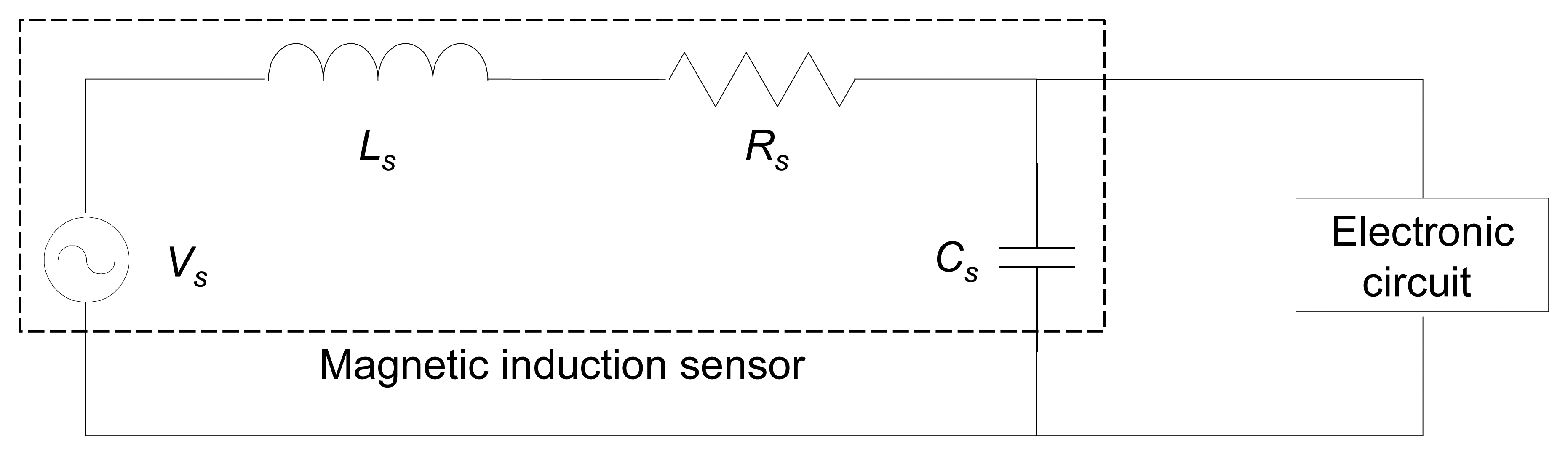
To estimate the induction voltage of the MMIS, the MMIS is coupled with an external electric circuit, as shown in Fig. 5. The inductance, resistance and capacitance of MMIS are based on the measured or assumed values at a voltage of 1 V and a frequency of 500 Hz. The measured inductance and resistance of MMIS are 4.0 mH and 31.1 Ω, respectively. The parasitic capacitance of the MMIS is assumed to be 0.1 pF [16]. The sensor is supposed to rotate at 30,000 rpm with an angle between magnetic field and ammunition rotation axis, θ, of 90°.
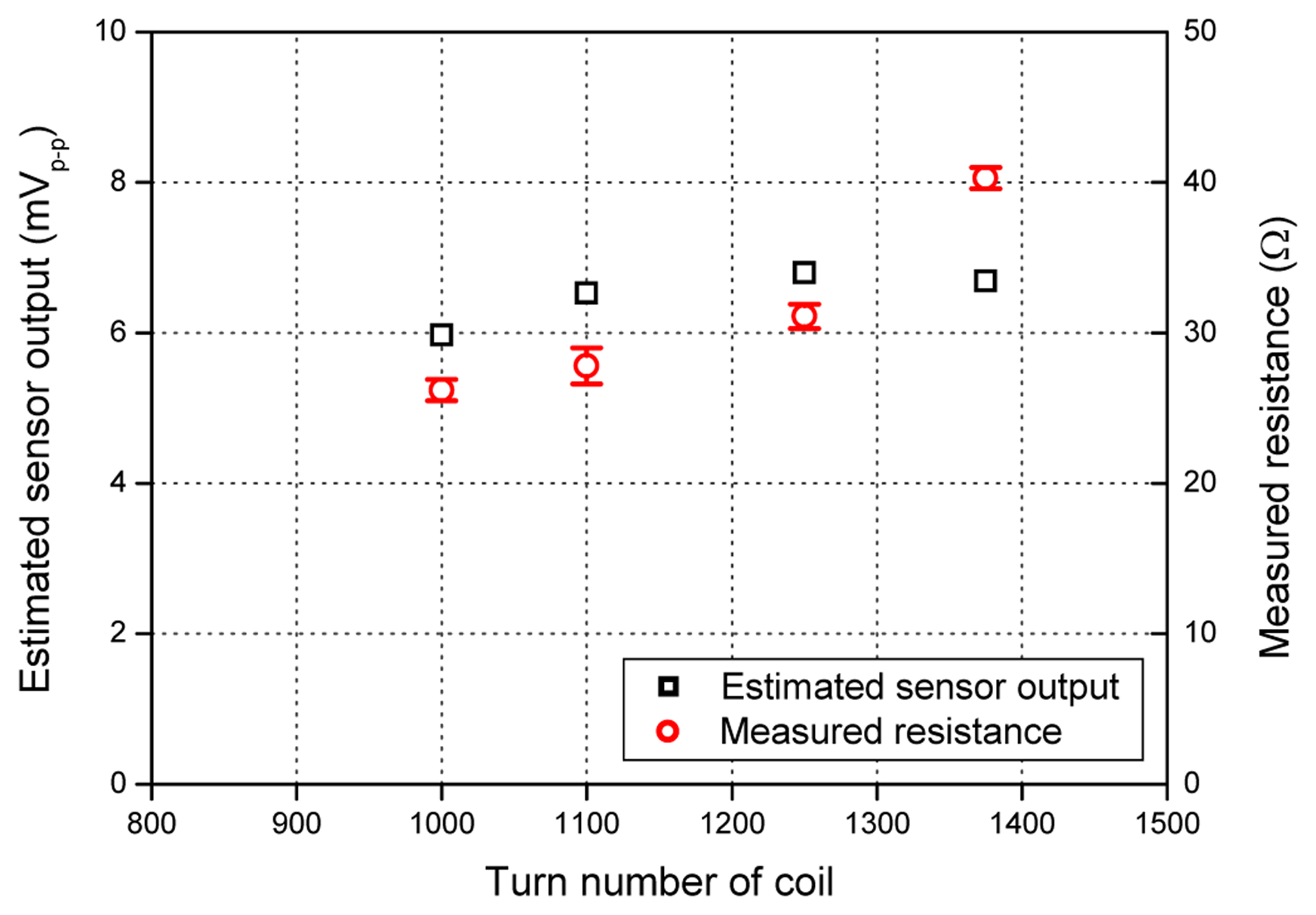
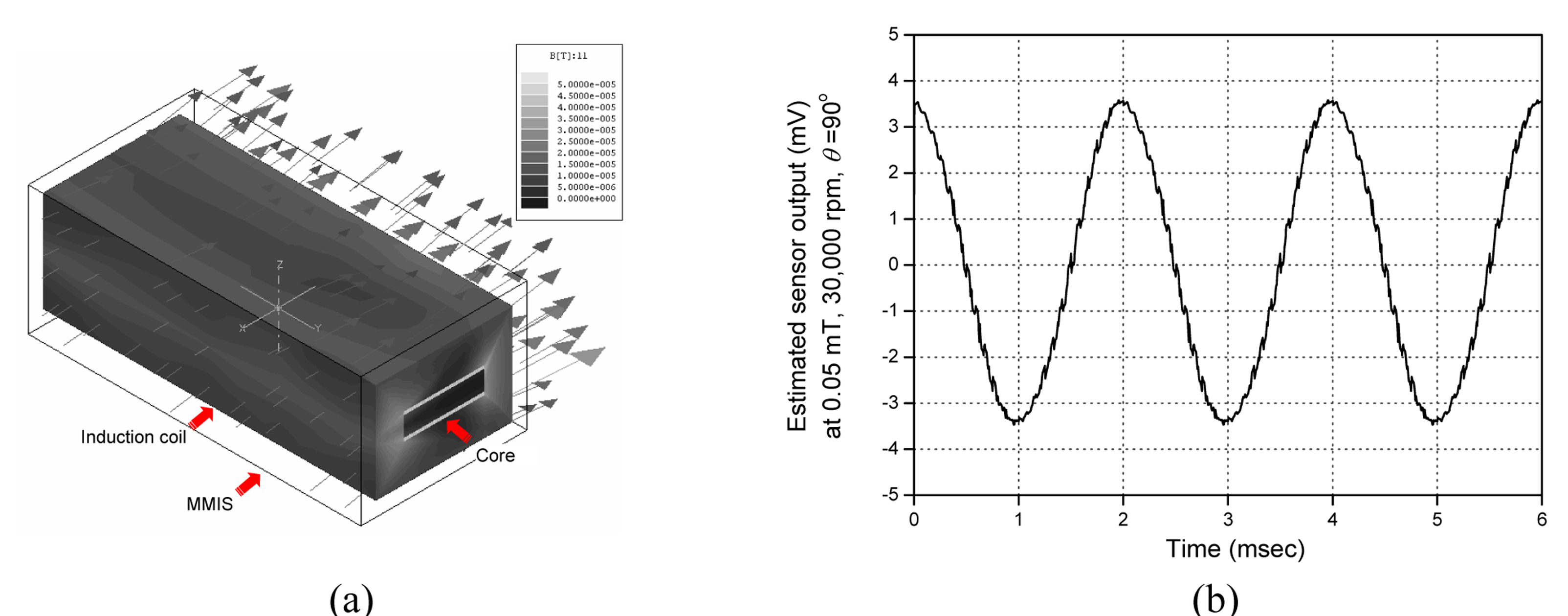
To determine the optimal turn number of the coil, the sensor output of the MMIS is estimated, as shown in Fig. 6, and the turn number of the coil is determined to be 1250 based on the simulation results, considering a stray effect in the core's ends and the sensitivity of the MMIS. Figure 7 shows the estimated magnetic flux density distribution and the estimated induction voltage of the MMIS. The estimated induction voltage of the fabricated MMIS at 0.05 mT and 30,000 rpm is 6.8 mVp-p. Based on the simulation results, the detailed dimensions of the MMIS are determined, as summarized in Table 2.
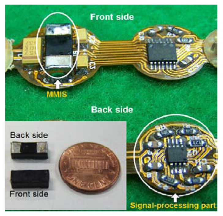
Figure 8 shows the photograph of the fabricated MMIS and the sensor assembly with the signal-processing part. The length, width, height and weight of the fabricated MMIS are 9 mm, 4.5 mm, 3.5 mm and 0.55 g, respectively.
4. Experimental Results
A couple of tests are performed: First, static MMIS test is an experiment for verifying the characteristics of the fabricated MMIS using a solenoid-coil test apparatus in a static environment. Secondly, dynamic MMIS test is a firing test for examining the operational characteristics and performance of the fabricated MMIS in a gunfire environment.
4.1. Static MMIS Test
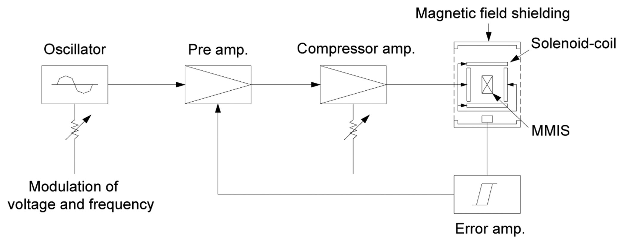
In the static MMIS test, the performance of the fabricated MMIS is measured in a static condition using the solenoid-coil test apparatus, as shown in Fig. 9, because it is hard to rotate the MMIS at a high rpm in geomagnetic field. To characterize the MMIS, the output signal of the MMIS is measured by varying magnetic flux density, rotational velocity and exposure time at the magnetic field. To measure the signal-to noise ratio (SNR) of the MMIS, the output signal and power spectrum of the MMIS are measured using a dynamic signal analyzer, HP35670A.
Figure 10 shows the measured sensor output signal and power spectrum at a magnetic flux of 0.05 mT, a frequency of 500 Hz and a temperature of 18°C. The measured power spectrum results indicate that the SNR of the fabricated MMIS is 44.0 dB. For reference, the power spectrum corresponding to noise is decided by averaging the power spectrum in a frequency bandwidth of 0∼5,000 Hz, ten times the frequency bandwidth of 500 Hz. The SNR results show that the fabricated MMIS has a low noise level and can be applied to the turn-counting fuze.
In the blind zone where the magnetic field direction is parallel to the ammunition rotation axis (θ=0°), the magnetic flux through the induction coil of the MMIS does not change and the sensor output is noise only. The noisy sensor signals with a signal-to noise ratio (SNR) of less than 8 dB or a duration time of less than 500 μsec are not taken into account as the input signals of the comparator, thereby resulting in missing turn count and dud ammunition. To prevent this disastrous probability, the turn-counting fuze counts the flight time using the internal clock of the microprocessor in the fuze and operates similar to the time-counting fuze when the sensor output is noise only. Figure 11 shows the measured SNR of the MMIS as a function of the angle between the magnetic field and the ammunition rotation axis. The experimental results prove that a small-caliber turn-count fuze can count the turn number of the ammunition correctly using the presented MMIS if the SNR is more than about 8 dB, which is corresponding to θ=6°. Figure 12 is the measured signals in the signal-processor, showing the original sensor output signal, amplified signal and pulse train.
To explore the linearity of the MMIS, the sensor output signal is measured in the magnetic flux density range of 0∼0.5 mT at a frequency of 500 Hz, an angle between the magnetic field and the ammunition rotation axis of 90° and the temperatures of -30°C (low), +18°C (medium) and +43°C (high). Figure 13 shows the average value of measured output signals of 10 sensors and the estimated sensor output signal as a function of magnetic flux density. The measured results indicate a nonlinearity of 0.59% in a magnetic flux density range of 0∼0.5 mT at a frequency of 500 Hz and a sensor output deviation of 5.9% in the temperature range of -30∼+43°C. It is observed from the measured results that the fabricated MMIS is almost insensitive to the temperature variation and that the turn-counting fuze including the MMIS can be used in any regions of the earth. In Fig. 13, the measured output signals show a deviation of 6.1% from the estimated output signals. This is because the magnetic loss in the core is not considered in the numerical analysis.
To investigate the effect of the rotational velocity on the sensor output signal, a magnetic field of 0.05 mT with the frequency band of 0∼10 kHz is applied to the fabricated MMIS. As shown in Fig. 14(a), the sensor output signal starts to saturate at a frequency of 1 kHz (60,000 rpm) and saturates completely at a frequency of 9 kHz (540,000 rpm). This is because the resistance of the MMIS increases when the frequency, that is, rotational velocity, increases. In the applications for small-caliber turn-counting ammunition that generally rotates at a rotational velocity of ∼60,000 rpm, the significant frequency response of the MMIS is in the frequency band of 0∼1 kHz, as shown in Fig. 14(b). The measured output signal shows that the nonlinearity of the MMIS is 1.77% at a magnetic flux density of 0.05mT in the frequency band of 0∼1 kHz. The frequency-normalized sensitivity (S/f) of the MMIS, given by (2), is 0.256±0.010 V/T·Hz, satisfying the sensitivity requirement of 0.1 V/T·Hz for turn count of small-caliber ammunition.
In the drift test for verifying the effect of exposure time in the magnetic field on the sensor output signal, the fabricated MMIS is placed in the magnetic field with a magnetic flux density of 0.05 mT and a frequency of 500 Hz during 60 min. Figure 15 shows the measured results of the drift test. On the basis of the test results, the drift of the MMIS is determined to be about 0.27%, showing that the MMIS is insensitive to long-term exposure to geomagnetic field. The measured static characteristics of the fabricated MMIS satisfy the general design requirements for turn count of small-caliber ammunition using geomagnetism.
4.2. Dynamic MMIS Test (Firing Test)
Firing test is performed to characterize the fabricated MMIS in a gunfire environment. The sensor output signal during flight is recorded by firing a 20 mm-diameter projectile including the MMIS (Fig. 16(a)) from a rifled gun (Fig. 16(b)). In the gunfire test that accompanies an approximately triangular shock with a peak acceleration of 30,000 g's and a duration of 1 msec, the induced voltage of the MMIS is sampled and recorded in an EEPROM memory by amplification, low-pass filtering and A/D conversion, in order.
In the firing test, the fabricated MMIS shows a peak-to-peak induction voltage of 5.5 mV that shows a deviation of 15.4% in the peak voltage value from measured value (6.5 mV) in the static test. This is because the firing test has been performed in the basement whose average magnetic flux density is 0.036∼0.040 mT less than that in the static test (0.05 mT). Figure 17 shows the recorded and estimated output signals of the MMIS in the firing test. In Fig. 17, the initial DC signal and noise are due to the titanium barrel of the rifled gun and the flight instability of the projectile, which is natural in ballistic aspect, respectively. The recorded sensor output signal also shows a deviation from the estimated sensor output signal. This is because the resistance and inductance of the MMIS, which are functions of frequency in general, are inputted on the basis of the measured values at a voltage of 1 V and a frequency of 500 Hz in the numerical analysis. The frequency of the induced voltage in the firing test is, however, 549 Hz. The estimated peak-to-peak voltage is, therefore, higher than the recorded peak-to-peak voltage. For reference, the estimated sensor output signal is a simulation result using Maxwell® 3D on the consideration of magnetic flux density of basement and real rotational velocity.
Through the firing test, the shock survivability of the fabricated MMIS in a gunfire environment of 30,000 g's is experimentally verified. After the firing test, the MMIS embedded in the fired projectile is retrieved and the static test on the MMIS is made at room temperature to examine the performance changes after high-g shock. The static test results labeled as 30,000 G are shown in Figs. 13, 14 and 15. The measured results lead us to the conclusion that the MMIS is almost insensitive to gunfire shock.
5. Conclusions
A miniaturized magnetic induction sensor (MMIS) has been presented for applications to the turn count of small-caliber ammunition in a high-g environment. To detect the turn of the small-caliber ammunition in a passive way, the MMIS using the high rpm rotation of the ammunition in geomagnetic field has been fabricated based on Faraday's law. The MMIS, composed of cores and a coil, had a robust and nonmoving structure to increase the shock survivability in a gunfire environment of ∼30,000 g's. The cores and coil of the MMIS have been designed on the basis of the simulation results of Maxwell® 3D, optimally miniaturizing the MMIS. In the static and dynamic MMIS tests, the fabricated MMIS has shown that an induction voltage of 6.5 mVp-p is generated at a magnetic flux density of 0.05 mT and a rotational velocity of 30,000 rpm. From the measured signal, the MMIS has shown a signal-to-noise ratio of 44.0 dB, a nonlinearity of 0.59%, a frequency-normalized sensitivity of 0.256±0.010 V/T·Hz and a drift of 0.27% in the temperature range of -30∼+43°C, which satisfies MIL-STD-810E. Firing test has proved that the MMIS can be used as a turn-counting sensor in a small-caliber smart ammunition. The operational characteristics and shock survivability of the fabricated MMIS in a gunfire environment of 30,000 g's have been also experimentally verified. It is foreseeable that the detectable minimum turn angle is improved by using dual or multi MMIS, resulting in more accurate estimation of a target range for air-bursting.
Acknowledgments
The authors would like to thank Hanwha Corporation for their technical support in characterizing the prototype MMIS.
References and Notes
- Buckley, A.; Freymond, P. H. 30mm Air Burst Munition ABM. Proceedings of the 35th NDIA Annual Gun and Ammunition Symposium, Williamsburg, USA, May 1–4, 2000.
- Timmerman, J. C. Air Bursting Munitions-A Systems Perspective. Proceedings of the 36th NDIA Annual Gun and Ammunition Symposium, San Diego, USA, April 9–12, 2001.
- Spencer, D.; Tiernan, T.; Solari, P.; Piering, F. Spin Rate Sensor for Fuzing Applications, Theory and Test Results Theory and Test Results. Proceedings of the 45th NDIA Annual Fuze Conference, Long Beach, USA, April 16–18, 2001.
- Elmore, R. E. HDL Yaw Sonde Instrumentation, HDL-TM-71-19; U.S. Army Material Command: Washington, D.C., 1971; pp. 8–12. [Google Scholar]
- ADIS16100 analog devices technical data; Analog Devices: Norwood. available at www.analog.com.
- Xiong, B.; Che, L.; Wang, Y. A. Novel Bulk Micromachined Gyroscope with Slots Structure Working at Atmosphere. Sensors and Actuat. A-Phys. 2003, 107, 137–145. [Google Scholar]
- Zhang, H.; Zhao, Y.; Yang, S.; Li, H. A. Novel Co-based Amorphous Magnetic Field Sensor. Sensors and Actuat. A-Phys. 1998, 69, 121–125. [Google Scholar]
- Kejik, P.; Chiesi, L.; Janossy, B.; Popovic, R.S. A New Compact 2D Planar Fluxgate Sensor with Amorphous Metal Core. Sensors and Actuat. A-Phys. 2000, 81, 180–183. [Google Scholar]
- Mapps, D.J.; Watson, M. L.; Fry, N. A. Double Bifilar Magneto-Resistor for Earth's Field Detection. IEEE T. Magn. 1987, 23, 2413–2415. [Google Scholar]
- Adelerhof, D.J.; Geven, W. New Position Detectors based on AMR Sensors. Sensors and Actuat. A-Phys. 2000, 85, 48–53. [Google Scholar]
- Daughton, J.; Brown, J.; Chen, E.; Beech, R.; Pohm, A.; Kude, W. Magnetic Field Sensors Using GMR Multilayer. IEEE T. Magn. 1994, 30, 4608–4610. [Google Scholar]
- Rieger, G.; Ludwig, K.; Hauch, J.; Clemens, W. GMR Sensors for Contactless Position Detection. Sensors and Actuat. A-Phys. 2001, 91, 7–11. [Google Scholar]
- Test Method Standard for Environmental Engineering Considerations and Laboratory Tests, MIL-STD-810E; U.S. Department of Defense: Washington, D.C., 1989; pp. 501.3.1–13.
- Ripka, P. Magnetic Sensors and Magnetometers; Artech House: Norwood, 2001; pp. 57–64. [Google Scholar]
- Yoon, S.-H.; Oh, J.-S.; Lee, Y.-H.; Lee, S.-W. Miniaturized Inertia Generators as Power Supplies for Small-Caliber Fuzes. IEEE T. Magn. 2005, 41, 2300–2306. [Google Scholar]
- McLyman, C. W. T. Transformer and Inductor Design Handbook; Marcel Dekker inc.: New York, 1978; pp. 200–203. [Google Scholar]
Figure 1.
Comparison between estimated burst ranges of time-counting and turn-counting fuzes as function of muzzle velocity deviation using simulation results of PRODAS®, where nominal muzzle velocity and nominal burst range are assumed as 200 m/s and 500 m, respectively.
Figure 1.
Comparison between estimated burst ranges of time-counting and turn-counting fuzes as function of muzzle velocity deviation using simulation results of PRODAS®, where nominal muzzle velocity and nominal burst range are assumed as 200 m/s and 500 m, respectively.

Figure 2.
Structure of MMIS.

Figure 3.
Block diagram of signal-processor in turn-counting fuze.

Figure 4.
Working principle of turn-counting fuze with MMIS.

Figure 5.
Equivalent circuit of MMIS.

Figure 6.
Estimated induction voltage of MMIS and measured resistance as function of turn number of coil at magnetic flux density of 0.05 mT, rotational velocity of 30,000 rpm and angle between magnetic field and ammunition rotation axis of 90°.
Figure 6.
Estimated induction voltage of MMIS and measured resistance as function of turn number of coil at magnetic flux density of 0.05 mT, rotational velocity of 30,000 rpm and angle between magnetic field and ammunition rotation axis of 90°.

Figure 7.
Simulation results of MMIS at magnetic flux density of 0.05 mT, rotational velocity of 30,000 rpm and angle between magnetic field and ammunition rotation axis of 90°: (a) Estimated magnetic flux density distribution; (b) Estimated induction voltage of MMIS as function of time.
Figure 7.
Simulation results of MMIS at magnetic flux density of 0.05 mT, rotational velocity of 30,000 rpm and angle between magnetic field and ammunition rotation axis of 90°: (a) Estimated magnetic flux density distribution; (b) Estimated induction voltage of MMIS as function of time.

Figure 8.
Photograph of MMIS and signal-processing part in turn-counting fuze.

Figure 9.
Experimental apparatus for static characterization of fabricated MMIS.

Figure 10.
Measured sensor output signal of fabricated MMIS at magnetic flux density of 0.05 mT, frequency of 500 Hz and angle between magnetic field and ammunition rotation axis of 90°: (a) Voltage output; (b) Power spectrum output.
Figure 10.
Measured sensor output signal of fabricated MMIS at magnetic flux density of 0.05 mT, frequency of 500 Hz and angle between magnetic field and ammunition rotation axis of 90°: (a) Voltage output; (b) Power spectrum output.

Figure 11.
Measured SNR of MMIS as function of angle between magnetic field and ammunition rotation axis.
Figure 11.
Measured SNR of MMIS as function of angle between magnetic field and ammunition rotation axis.

Figure 12.
Measured sensor signals in signal-processor, where Ch1, Ch2 and Ch3 denote original signal, amplified signal and pulse train, respectively.
Figure 12.
Measured sensor signals in signal-processor, where Ch1, Ch2 and Ch3 denote original signal, amplified signal and pulse train, respectively.

Figure 13.
Measured and estimated output signals as function of magnetic flux density.

Figure 14.
Measured and estimated output signals as function of rotational velocity in frequency bands of: (a) 0∼10 kHz; (b) 0∼1 kHz.
Figure 14.
Measured and estimated output signals as function of rotational velocity in frequency bands of: (a) 0∼10 kHz; (b) 0∼1 kHz.

Figure 15.
Measured drifts of fabricated MMIS at magnetic flux density of 0.05 mT and frequency of 500 Hz.
Figure 15.
Measured drifts of fabricated MMIS at magnetic flux density of 0.05 mT and frequency of 500 Hz.

Figure. 16.
Experimental setup for MMIS firing test: (a) Sample projectile with MMIS; (b) Prototype rifled gun.
Figure. 16.
Experimental setup for MMIS firing test: (a) Sample projectile with MMIS; (b) Prototype rifled gun.

Figure 17.
Recorded and estimated sensor output signals in firing test.


| Item | Specification |
|---|---|
| Length / Width / Height | ≤ 10 × 5 × 5 mm |
| Weight | ≤ 1 g |
| Frequency bandwidth | 100∼1,000 Hz |
| Sensitivity at 0.05 mT and 500 Hz | ≥ 0.1 V/T·Hz |
| Shock limit | 30,000 g's |
| Temperature range | -30∼+43 °C |
| Component | Item | Value |
|---|---|---|
| Core ribbon | Length / Width / Height | 8.0 mm / 2.2 mm / 0.02 mm |
| Coil | Diameter Turn number | 50 μm 1250 |
| Molding | Length / Width / Height | 9.0 mm / 4.5 mm / 3.5 mm |
| Signal-processor | Gain Reference voltage at comparator | ×84 50 mV |
| Measured inductance | 4.0 mH | |
| Measured resistance | 31.1 Ω | |
© 2006 by MDPI ( http://www.mdpi.org). Reproduction is permitted for noncommercial purposes..
Share and Cite
MDPI and ACS Style
Yoon, S.-H.; Lee, S.-W.; Lee, Y.-H.; Oh, J.-S. A Miniaturized Magnetic Induction Sensor Using Geomagnetism for Turn Count of Small-Caliber Ammunition. Sensors 2006, 6, 712-726. https://doi.org/10.3390/s6070712
AMA Style
Yoon S-H, Lee S-W, Lee Y-H, Oh J-S. A Miniaturized Magnetic Induction Sensor Using Geomagnetism for Turn Count of Small-Caliber Ammunition. Sensors. 2006; 6(7):712-726. https://doi.org/10.3390/s6070712
Chicago/Turabian StyleYoon, Sang-Hee, Seok-Woo Lee, Young-Ho Lee, and Jong-Soo Oh. 2006. "A Miniaturized Magnetic Induction Sensor Using Geomagnetism for Turn Count of Small-Caliber Ammunition" Sensors 6, no. 7: 712-726. https://doi.org/10.3390/s6070712