1. Introduction
Recently, many researches have been performed in the field of industrial MEMS (Micro Electromechanical System) technology, which is one of the leading edge technologies, to manufacture various highly profitable micro parts based on the silicon micro machining technologies. Such MEMS technologies are being widely applied for industrialization, such as high efficient sensors and control systems in the aerospace field, and micro switches and distributors in the optical and wireless communication fields, etc. [
1]
One of the important applications of the MEMS technology is the acceleration sensor, which is widely used in various industrial fields including automobile industry. Up to now, various types of silicon-based sensors have been developed due to its advantages; the reliability and the mass productivity are good since the existing semi-conductor fabrication facilities can be used, and smaller and lighter sensors can be fabricated. [
2-
6] Also, the wet etching process and the deep reactive ion etching (DRIE) are introduced to fabricate the sensors with bigger vibrating mass and higher aspect ratio. [
7-
8] Current silicon-based acceleration sensors can be categorized into the capacitive type (using surface micromachining on the polycrystalline silicon) and the piezoresistive type (using bulk micromachining on the single crystal silicon). Recently, it is being tried to manufacture glass-based acceleration sensors due to the lower initial investment costs. [
9-
11] However, the sensitivity of the glass-based sensors is lower than that of the silicon-based sensors. Thus, it is required to develop more advanced and effective methods to fabricate such various sensor types.
In this study, the micro powder blasting process, one of the mechanical etching methods those can replace the existing chemical etching processes, was applied to fabricate the vibrating mass and the cantilever beam of the acceleration sensor with the Pyrex glass which has similar mechanical properties to silicon. To investigate the machining characteristics of the glasses, a series of preliminary experiments were performed by varying the process parameters, such as the blasting pressure, the mass flow rate of the abrasive, and the number of scanning times, etc. From the results, the optimum process parameters were determined for the sensor body fabrication. Metal masks were designed and formed using EDM process. Machined shapes of the sensor body were measured and analyzed using a 3-dimensional profiler.
As the results of this study, the possibility was verified to apply the powder blasting method for the fabrication of the acceleration sensor body with lower manufacturing cost and higher productivity compare to the current silicon-based sensor fabrication methods.
2. Basic Principle of the Piezoresistive Acceleration Sensor
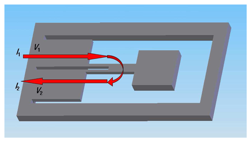
Currently available acceleration sensors can be classified into piezoelectric type, capacitive type and piezoresistive type. In this study, the piezoresistive type acceleration sensor was a target to manufacture using the micro powder blasting method. The basic structure of the accelerometer is shown in
Fig.1. This sensor has a vibrating mass clings to a cantilever, and piezoresistive material layer is coated on it using vapor diffusion. In using the sensor, acceleration and bending amounts of the cantilever can be detected by measuring the piezoresistance and the strain gage film resistance. Generally, these 2 physical amounts can be detected as signals by transforming the strain of the beam caused by bending deformation into resistance change as the following equation. [
9]
where,
Δl/
l is the elongation per unit length (strain) of the piezoresistive material film for given load, and
K is the gage constant.
K is about 2 for the platinum film, and 100∼200 for the polycrystalline silicon film. Acceleration can be calculated from the voltage change measured between
V1 and
V2 when the current is imposed between
I1 and
I2 as shown in
Figure 1.
3. Basic Principles of the Micro Powder Blasting
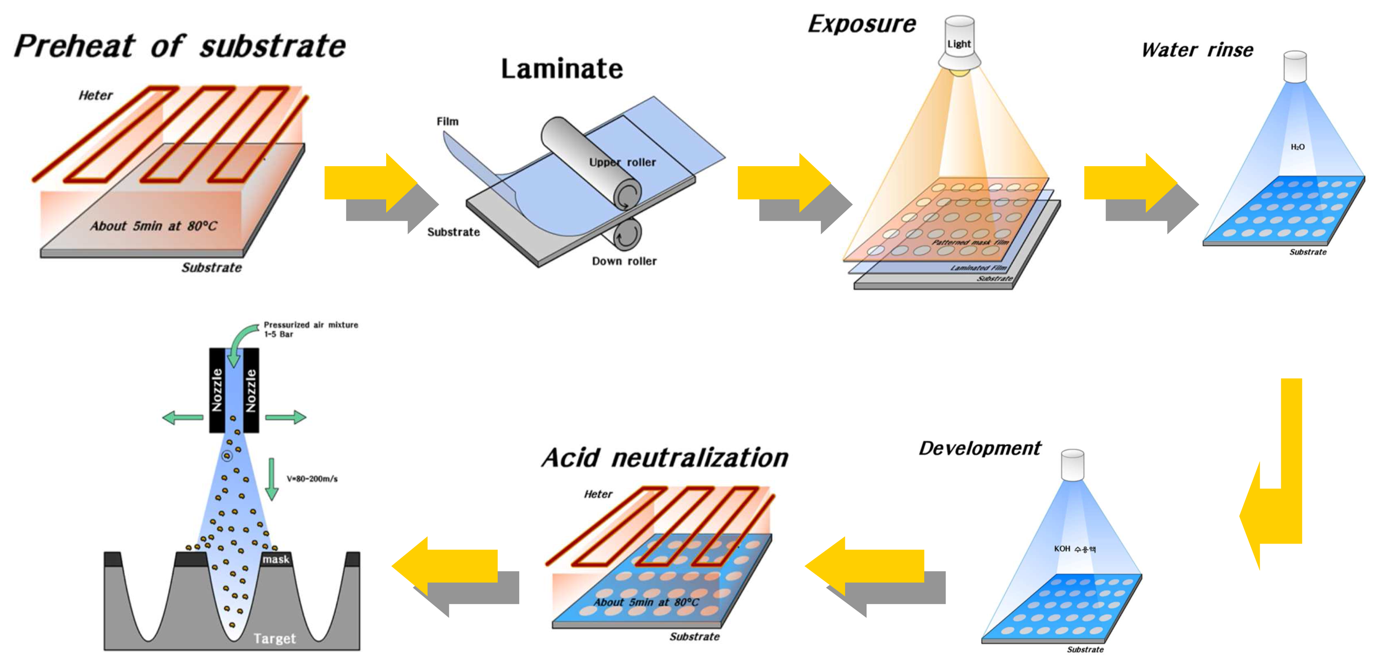
The basic machining principle of the micro powder blasting is shown in
Figure 2. In the process, micro abrasives (tens of mm), accelerated by highly compressed air or gases, are forced through a micro nozzle, and collide with hard and brittle workpieces at a very high velocity (80 – 200m/s) and density. Since the material removing process of micro powder blasting is performed by an integration of brittle mode machining based on micro crack propagation, there is very little heat, chipping, and crack generation in the workpiece. Thus, this method is very suitable for the machining of micro shapes (such as grooves, holes, pockets, etc.) of hard and brittle materials (such as glass, ceramics, silicon, and crystal, etc.). A rebounded mixture of abrasives and chips from the workpiece are sent to the distributor, which then separates the mixture into chips and abrasives for recycling.
According to the machining model proposed by Silkkeryeer et al. [
12], when a sharp indenter tip moves down to the inside of the workpiece, a plastic deformation zone is formed under the indenter tip due to the compressive force. The formed plastic zone becomes larger as the compressive force increases. Eventually, radial/median and lateral cracks are formed along the perpendicular and parallel direction of the surface, respectively. At this time, it can be assumed that the lateral cracks have relationships with the workpiece removal process in the micro powder blasting, and the radial/median cracks have relationships with the surface crack formation. It plays a key role to accelerate the removal process at some level as the machined depth is increased.
Process parameters to define the micro powder blasting are: (1) blasting pressure, time and velocity, (2) material properties, size and density of the abrasives, (3) velocity and number of nozzle scanning times, and (4) stand-off distance (distance between the nozzle and workpiece). Such parameters should be appropriately determined to improve machining accuracy and efficiency.
4. Machinability Evaluation of the Glasses
Mechanical properties of the boron-silicate Pyrex glass (used for sensor packaging) and the soda lime glass (used for general purpose plate glass) are listed in
Table 1 and
2, respectively. Their machining characteristics in the micro powder blasting processes using WA#600 micro abrasives are compared as follows:
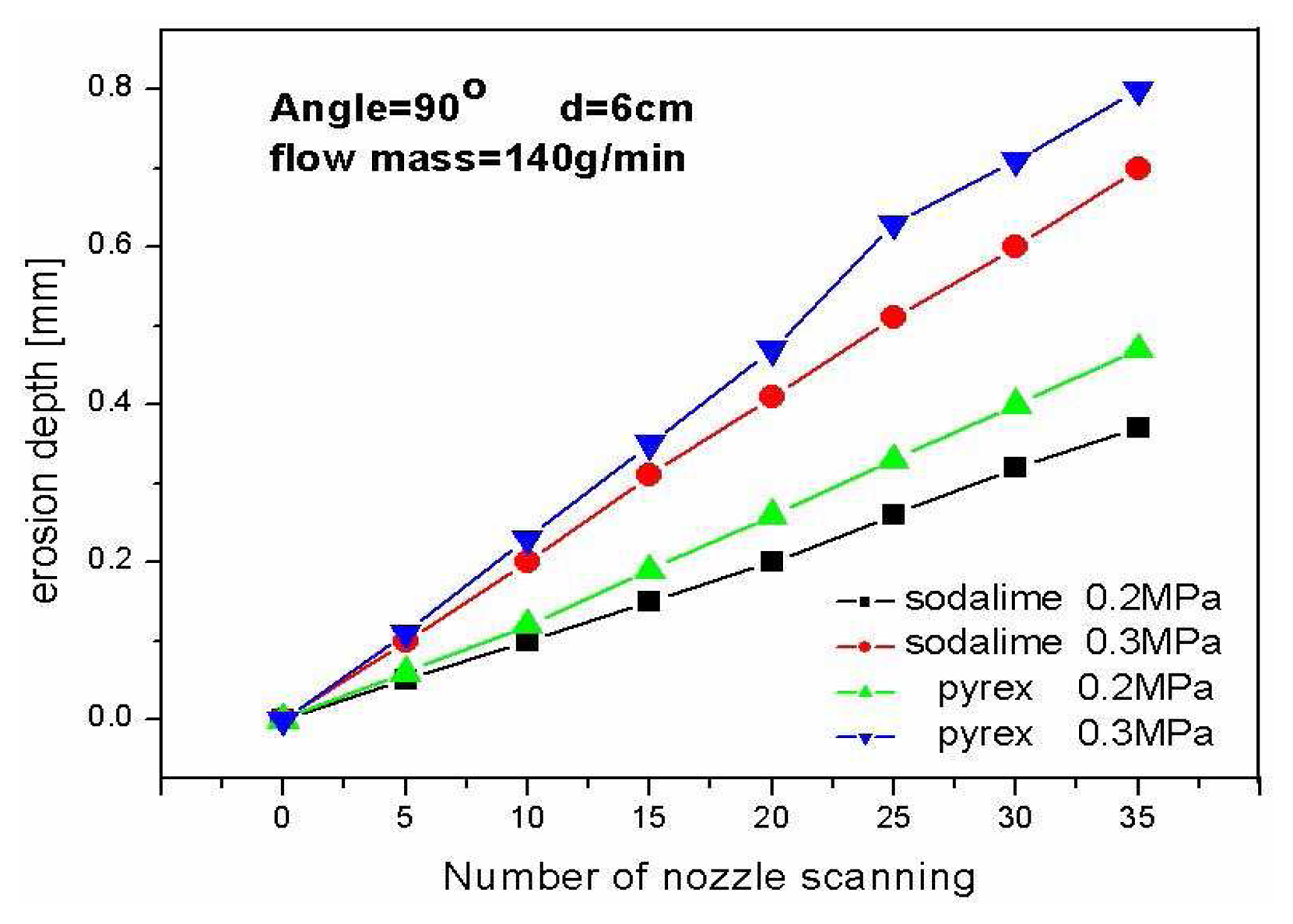
Figure 3 shows the effect of the blasting pressure and number of nozzle scanning times to the erosion depths of the glass. It can be seen from the figure that the erosion depth increased as the blasting pressure and number of scanning times increase.
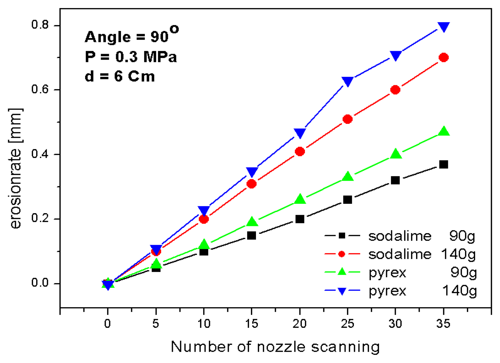
Figure 4 shows the variation of erosion depth by changing the mass flow rate of abrasives from 90g/min to 140g/min. The erosion depth increased with the increase of the mass flow rate since more abrasives in the same hit zone can promote more micro cracks.
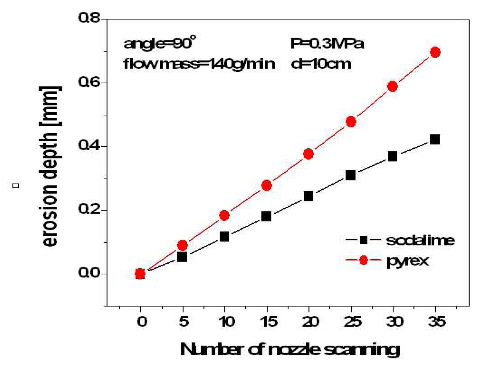
Figure 5 is to compare the machinabilities of the glass materials according to the increase of nozzle scanning times. The erosion depth of the Pyrex glass increased almost constantly by 80∼100
μm for every 5 nozzle scanning times.
From the figures, it can be seen that the Pyrex glass has very good machinability for the micro powder blasting since the Pyrex glass has higher hardness and brittleness than those of soda lime glass. Such result shows that the powder blasting method is adequate for the machining of brittle materials such as glass. As a result, in this study, the Pyrex glass was selected as a base material to fabricate desired acceleration sensor since it has better machinability and productivity than other glasses in powder blasting process.
5. Experimental Works
5.1. Sensor Design and Analysis
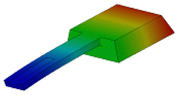
An acceleration sensor was designed for this research, which has the size of 1.7×1.7×0.6mm for the vibrating mass, and of 2.9×0.7×0.2mm for the cantilever beam. At the lower end of the cantilever, a micro channel was designed for electrical wiring, which is 1.5×0.3×0.06mm. A modal analysis was performed to the modeled cantilever beam of the sensor using NISAII (EMRC) (
Figure 6); and 2,681.2Hz was obtained as the first natural frequency.
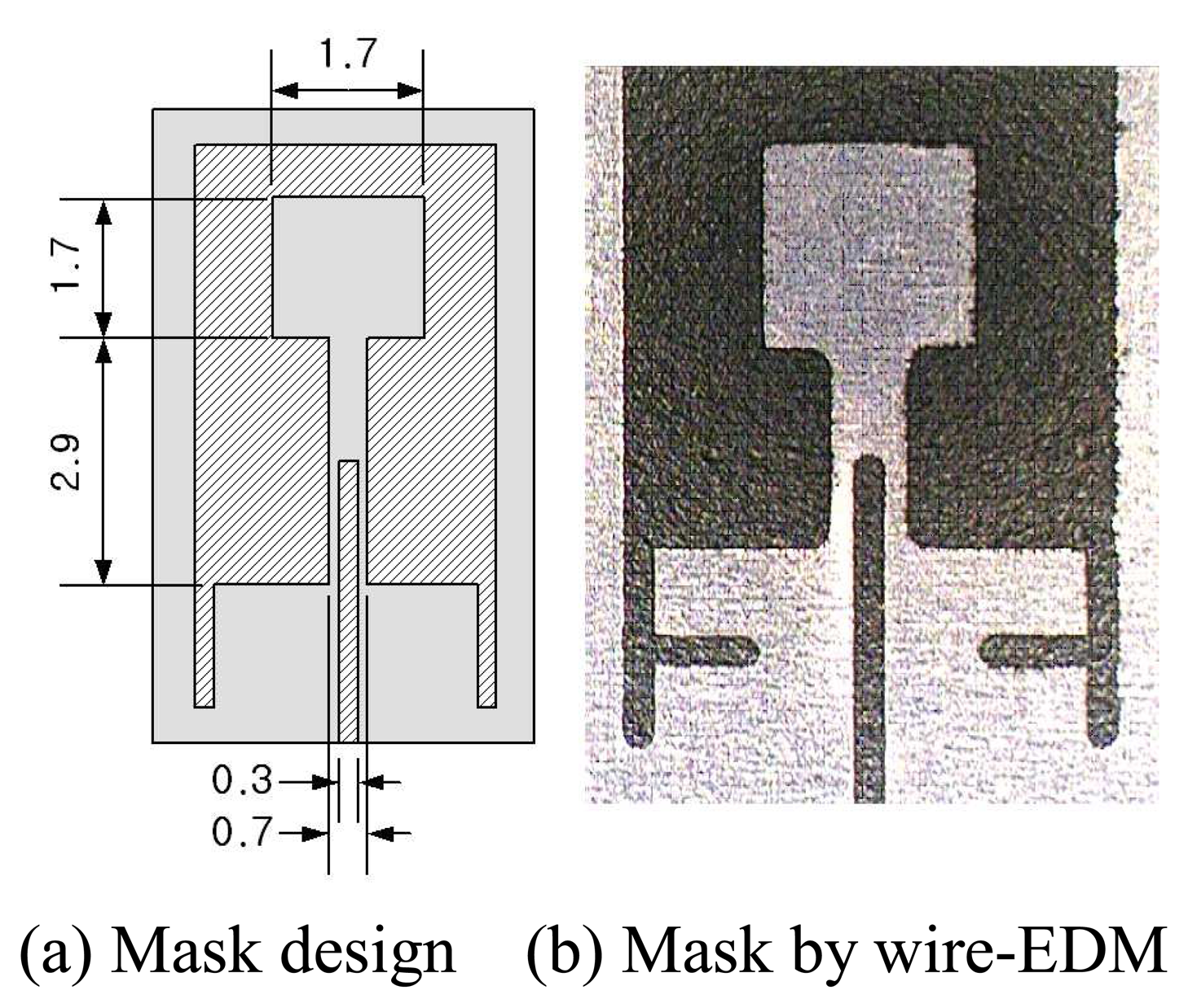
5.2. Mask Design and Masking
For the micro powder blasting, the polymer masks (used for semiconductor process), and the metal masks (such as copper, aluminum and stainless steel, etc.) can be used. In this research, the metal masks, made with the aluminum thin plate (t=0.5mm), were used to simplify the sensor fabrication process. To improve the sensitivity of the sensor, the lower end of the cantilever beam should be formed thinner than other regions. To do this, 2 types of masks were required; a mask for protecting the planar shapes of the cantilever beam and the vibrating mass, and a mask for the additional machining to make the lower end thinner.
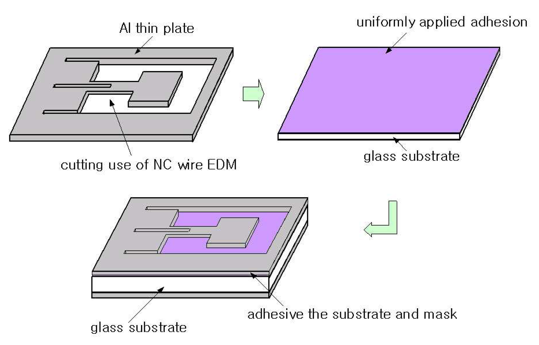
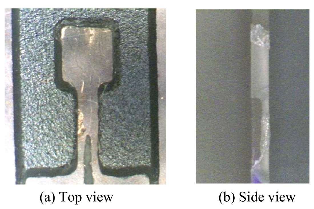
Figure 7(a) shows the designed mask shape (unit = mm); and (b) shows the prepared aluminum mask using NC EDM process. The masking process to the Pyrex glass using prepared metal masks is shown in
Figure 8.
5.3. Micro Powder Blasting Process
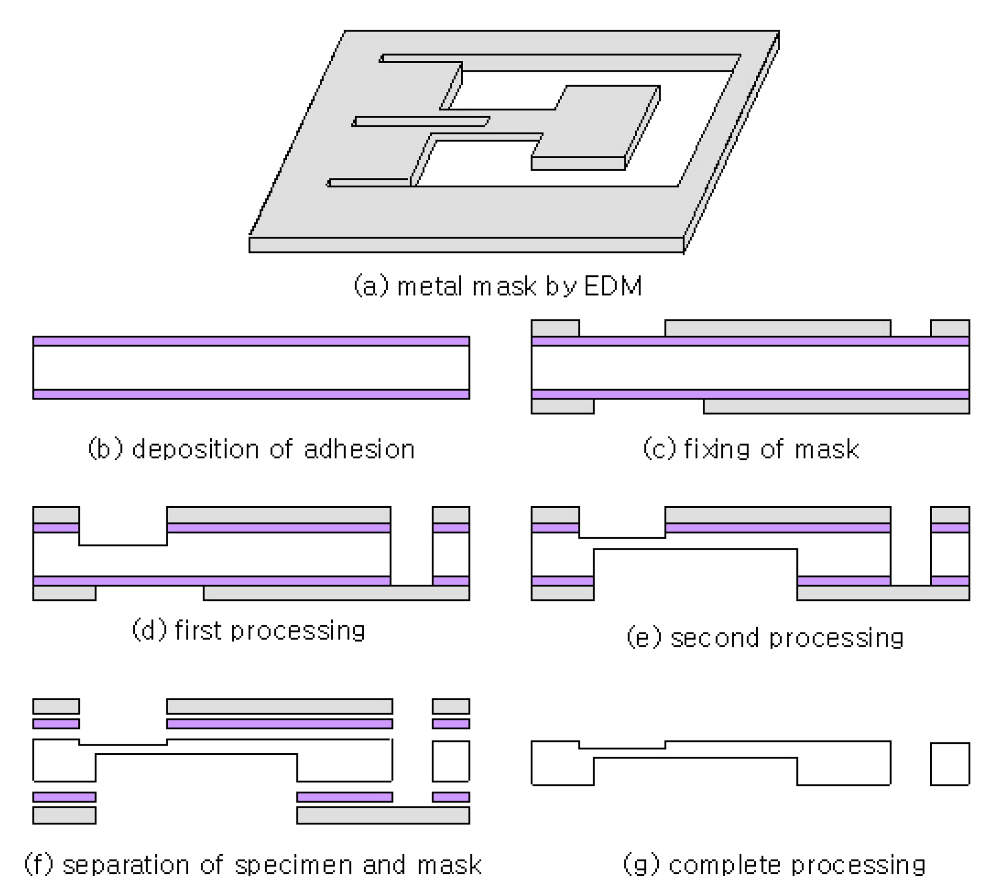
The process flow for the sensor fabrication is illustrated in
Figure 9. As a first step, prepared metal masks were bonded on the both sides of the specimen for sensor body. Next, the micro powder blasting process was performed to the masked specimen. In this research, the powder blasting process was composed of two steps; the first processing was to form the planar shapes of the whole sensor body (
Figure 9(d)), and the second processing is to make the lower end of the cantilever beam thinner at the reverse side of the sensor body (
Figure 9(e)).
For the experiments, Microblaster (Sintobrator, MB-1) and a ceramic nozzle of 8mm diameter were used. Before the main experiments, a series of preliminary experiments were performed to obtain the optimum blasting conditions by varying the required process parameters. The blasting velocity and the mass flow rate of the abrasive, which strongly affect the erosion rate of the specimen, were changed to determine appropriate conditions. Based on the preliminary experiments, the most appropriate process parameters were decided as shown in
Table 3. The stand-off distance of the nozzle was set to 100mm to obtain uniform blasting effects. The number of nozzle scanning times was set to 30 to penetrate the specimen of 0.6mm thickness to make the planar shapes of the mass and the cantilever beam at the first processing, and 20 to remove additional depth of 0.4mm for the lower end of the cantilever beam at the second processing. After the blasting processes are done, a cleaning process was followed to remove the adhesives used to bond the mask to the specimen. Then, the acceleration sensor fabrication process was finished.
6. Result Analysis and Discussion
6.1. Shape Analysis and Sensor Structure
A precision tool microscope (Sony, High Scope KH1000) and a non-contact type optical 3-dimensional measuring machine (Veeco, Wyco NT-1000) were used to analyze the machined shape and the surface roughness of the specimen. To improve the accuracy of the results, average values were calculated after measuring 4 times.
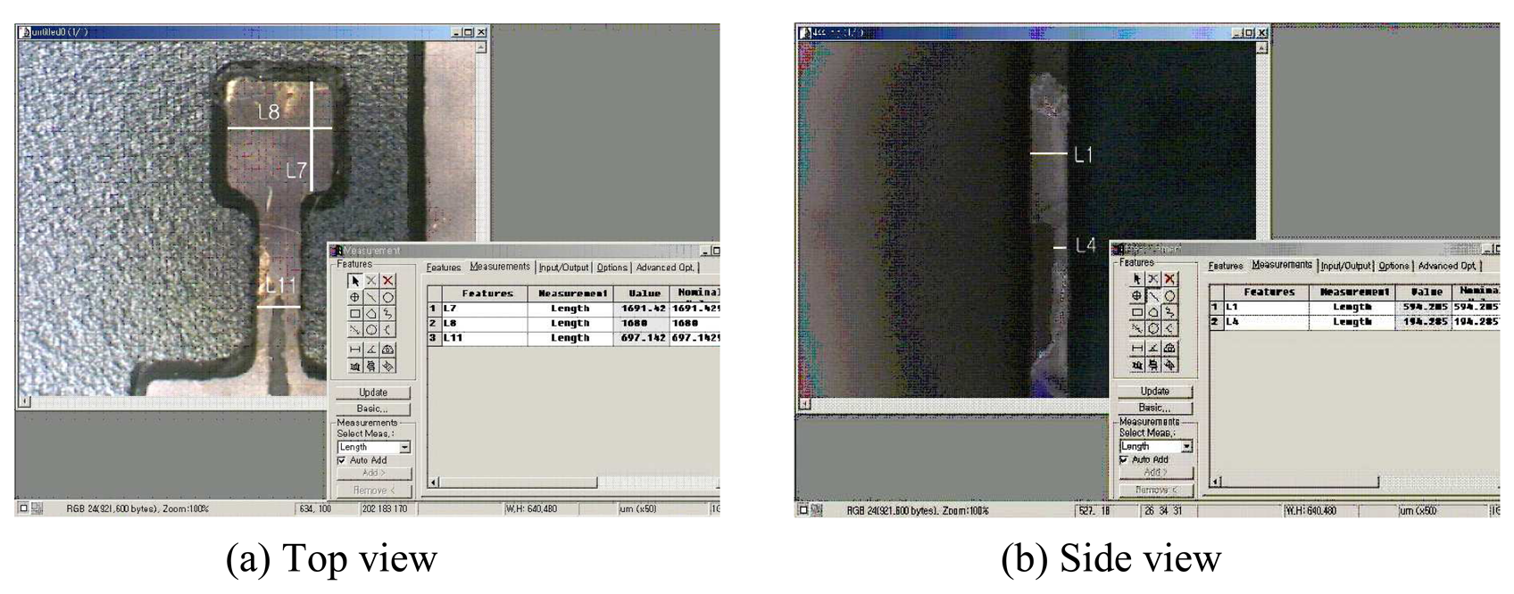
Figure 10 shows the machined shapes of the acceleration sensor body. From the figure, it can be seen that it almost coincides with the designed model. However, it was observed that the straightness errors of the cantilever beam and the mass along the edges were bigger than those of other regions. Such result was considered that the irregularly applied adhesives during masking process acted like another mask to prevent desired erosion of the specimen. Also, it was observed that the bottom side became wider than the top side of the specimen; such phenomenon was considered to be caused by the basic characteristics of the process itself that it was not easy to obtain perpendicular walls using the blasting process.
Figure 11 shows the machining error estimation of the specimen at specific 5 locations. The dimensional errors at the locations were estimated about 9∼20 μm, those can be considered to coincide with the designed values. The estimated results are listed in
Table 4.
6.2. Shape Analysis of the Micro Channel
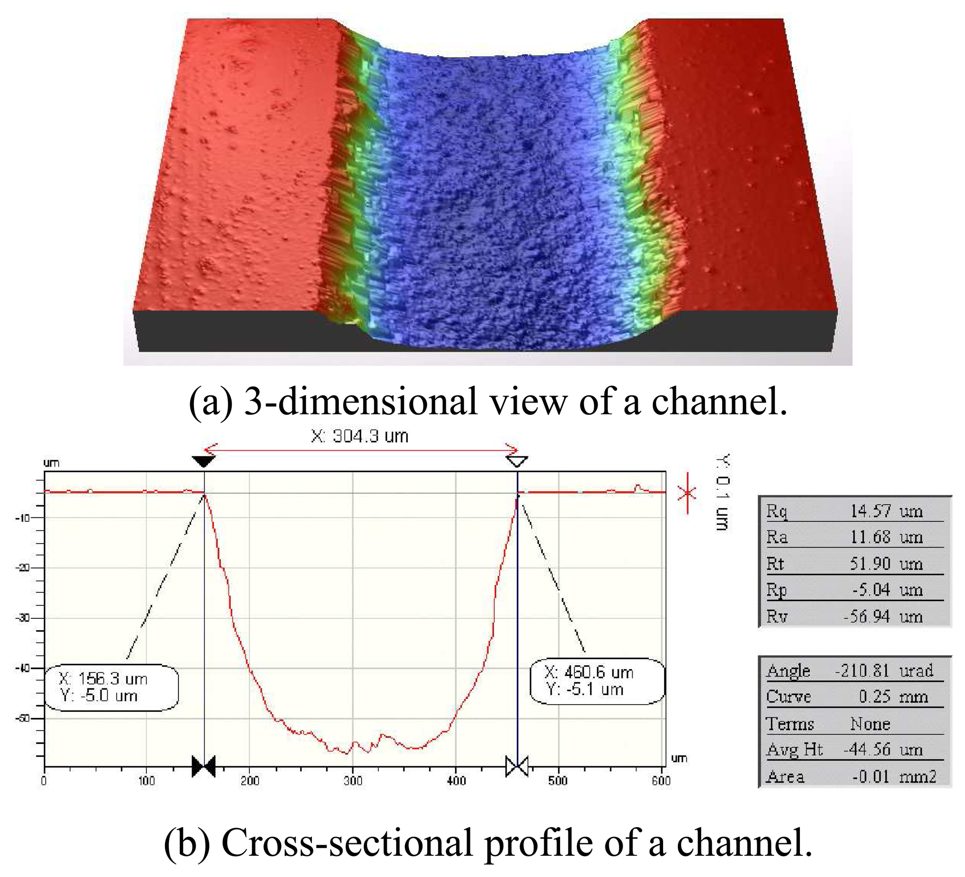
In this study, a micro channel was machined also for the electrical wiring of the acceleration sensor. The measured 3-dimensional shape and cross-sectional profile using a 3D profiler are shown in
Figure 12. As shown in the figure, the width of the channel had about 4 μm machining errors, and about 60 μm depth was obtained with 3 nozzle scanning times. Obtained surface roughness of the channel was Ra=0.5∼0.6 μm.
7. Conclusions
In this study, the micro powder blasting technique was applied to fabricate piezoresistive type acceleration sensor body with Pyrex glass. To decide optimum process parameters for the micro powder blasting, a series of preliminary experiments were performed; and aluminum masks were designed and machined using EDM process for the process. The conclusions of this study can be summarized as follows:
- (1)
The cantilever beam, the vibrating mass and a micro channel of the sensor body can be fabricated using the micro powder blasting method.
- (2)
It was possible to obtain almost exact shapes, compared to the designed dimensions, within 20 μm error range using metal masks and imposed process conditions.
- (3)
It was investigated that further advanced masking methods were required to improve the straightness errors at the edges and form accuracy of the sensor body.
- (4)
From the results of this study, it was demonstrated that the existing silicon-based micro-machining method can be replaced by the micro powder blasting method using the Pyres glass.
- (5)
Such method showed an effective and possible way to fabricate the glass-based acceleration sensors more economically with higher productivity.


