Proposal for an Ultrasonic Tool to Monitor the Osseointegration of Dental Implants

Laboratory of Instrumentation and Microelectronics, Department of Electrical Engineering, São Carlos School of Engineering, University of São Paulo, Av. Trabalhador São-carlense, 400, São Carlos 13560-590, SP, Brazil
*
Author to whom correspondence should be addressed.
Sensors 2007, 7(7), 1224-1237; https://doi.org/10.3390/s7071224
Submission received: 21 March 2007
/
Accepted: 19 June 2007
/
Published: 16 July 2007
(This article belongs to the Special Issue Physiological Sensing)
Abstract
:The longevity of dental implants depends on osseointegration, which provides load-bearing capacity without putting the prosthesis at risk from micromotions at the implant-bone interface. This research involved an analysis of the viability of an ultrasonic evaluation tool to quantify osseointegration. Ultrasonic transmission is directly dependent on the difference between the acoustic impedance of materials in intimate contact with each other. The closer their acoustic impedances the more intense their transmission. Therefore, an analysis of the ultrasonic echoes would presumably allow for a quantitative evaluation of the bone tissue that has grown into the pores of the implant. In addition, the literature reports that bone fracture healing can be accelerated by the application of a controlled low-amplitude mechanical stimulus on the site of the lesion. In fact, acoustic pressure waves of low-intensity pulsed ultrasound are reportedly a secure technique for promoting mechanical stimulus without impairing the healing process. Many experimental and clinical trials have confirmed that daily transcutaneous ultrasound applications on the injured site are beneficial to the enhancement of fractured bone. This proposal aims to bring together the characteristics of ultrasound propagation and the positive effect of ultrasound on bone growth into a single tool that quantitatively monitors the evolution of the osseointegration process. The viability of a device with these features was investigated through simulations and experimentally. The initial simulations were conducted to explore the influence of waveguide shapes on the tool's sensitivity to changes in the implant supporting media. The waveguides were designed in two parts, one consisting of a screw-shaped part to attach to the implant and the other a conical or step-shaped part to which the ultrasonic source was fixed in the first simulations. The step-shaped waveguide proved to be the more sensitive; intermediate stages of the osseointegration process were simulated and experiments were conducted with the step-shaped aluminum waveguide attached to a cylindrical aluminum nut embedded at different depths, so that the results obtained were only due to lateral attachment of the parts. These devices indicated that the transmission of ultrasound through the lateral surface of the implant by dilatational waves could render this tool suitable for monitoring the osseointegration of dental implants.
1. Introduction
The techniques most commonly used today for monitoring implant stiffness are the Periotest [1] and resonance frequency analysis (RFA) [2], both of which involve stimulating the implant mechanically and measuring its mechanical response. These data can be measured from time to time to monitor the stiffness of the implant in the bone tissue. A review of the RFA and Periotest techniques indicated that neither of these methods identify the bone/interface characteristics or provide a quantitative evaluation of bone tissue integration [3]. The results of these techniques depend on features such as the characteristics of the bone tissue and the implant sink depth, but neither of these methods has a minimum value to determine a prognosis of implant failure. In fact, the literature reports that, to date, no clinical tool exists to evaluate the amount of osseointegration and stability around dental implants, but only to monitor changes in the stiffness of an implant in bone during healing [4]. This study proposes the development of a new ultrasonic technique to evaluate the stability of dental implants, taking into account the quantity of bone ingrowth in the surface pores of implants, unlike the principle of the current devices, which measure an implant's response to mechanical stimuli that attempt to cause micromovements.
The mechanical stimulus employed in the evaluation of implant stability must be of an extremely low-amplitude to avoid jeopardizing the process of osseointegration, since micromotions of the implant may cause the formation of fibrous tissue at the tissue-implant interface, preventing the microstructural fusion of bone and implant [5]. The tolerated micromotional threshold has been found to lie somewhere between 50 and 150 μm [6], beyond which the healing of the bone tissue and its intergrowth into porous implants are compromised. A review of the experimental literature indicates that it is not the absence of loading, but the absence of excessive micromotion at the implant-bone interface that is critical for osseointegration [7].
A different approach considers the evaluation of bone tissue ingrowth into porous implant surfaces by low-intensity, pulsed ultrasound. It is well known from the literature that a controlled application of low-amplitude mechanical stimulus enhances recovery [8]. Pulsed ultrasound is a pressure wave that promotes a safe noninvasive mechanical stimulus in the injured site with amplitudes as low as 0.3 nm (Ferroperm Piezoelectric Calculator), posing no risk to the recovery process. Although it is not totally understood how ultrasound produces a cellular response [9-10], many experiments and clinical trials have shown that ultrasound plays a positively beneficial role in the healing process as a whole [10-17], with daily applications of only a few minutes of low intensity pulsed ultrasound. The use of an ultrasonic device specially designed for monitoring the osseointegration process would allow for the continuous assessment of implant osseointegration while simultaneously stimulating bone tissue regeneration. Both features are novel in the area of implant technology, and would allow for individual assessments of dental implant fixation combined with an acceleration of the recovery period, diminishing implant failure rates and extending the implant's longevity.
The feasibility of a low-intensity pulsed ultrasound device was studied through simulations as well as experimentally. The procedures employed to define the waveguide dimensions which led to enhanced sensitivity are described in the materials and methods section. The results of this work revealed that the transmission of ultrasonic energy through a screw-shaped aluminum waveguide attached to a block of the same material in different levels fallout in clearly distinguishable signals, even with only lateral contact between the two parts. Moreover, the results reveal a linear relation between the detected energy and the degree of osseointegration, making this waveguide a potential tool for monitoring osseointegration.
2. Materials and Methods
The feasibility of an ultrasonic tool for measuring osseointegration was studied through simulations, followed by an experiment with an aluminum waveguide. The source and the receiver elements of the sensor consisted of a piezoelectric ceramic placed on the top base of the waveguide. The transmission of ultrasonic energy from the source to the implant requires mechanical contact between them, which was established by a waveguide with a screw-shaped body designed to fill the internal nut of a dental implant. The implant and the waveguide should be made of the same material, as the fewer the discontinuities of acoustic impedance the better the transmission.
2.1. Simulations
The simulations were made on Wave2000® Pro, a software program developed by CyberLogic® for computational ultrasonics that employs the finite difference method to describe the behavior of high-frequency acoustic waves. The program considers the elastic and viscous characteristics of the media through the coupled equations 1 and 2 [18], making the results highly accurate for two-dimensional ultrasound propagation.
Two different waveguide designs were implemented in the initial simulations in an attempt to determine the most efficient geometry to distinguish the surrounding media of an implant, i.e., which one detected greater differences between signals in response to changes in the surrounding media. Fig. 1 illustrates the shapes and dimensions of the waveguides, both of which have a screw-shaped body to attach to the implant.
An ultrasonic pulse with a central frequency of 1MHz, which is in the range of frequencies used in ultrasonic treatments to accelerate the healing of fractures [10], modulated by a sine Gaussian envelope with a unitary amplitude and a time constant of 0.75 μs was fed into the titanium structures by 10-mm diameter sources attached the top of the waveguides; the receptors were placed in the same positions. The step-shaped waveguide was chosen due to its greater sensitivity in detecting changes in the tissue surrounding the implant. Having defined the geometry of the waveguide, the attachment between the waveguide and the surrounding media was designed.
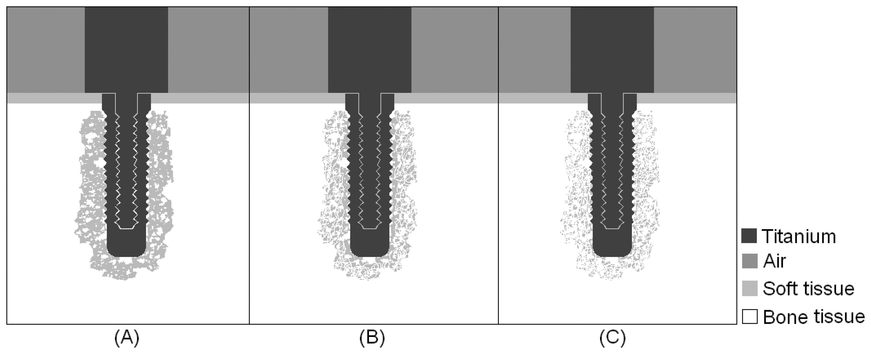
Simulations were carried out for three intermediate stages of the osseointegration process, in which the implant was embedded in a mixture of bone and soft tissue, with increasing concentrations of bone tissue, as indicated from left to right in Fig. 2. The results obtained in the first simulations of the step-shaped waveguide attached to the implant embedded in soft tissue and completely osseointegrated were used for comparison with the simulations of the intermediate stages.
2.2. Experiments
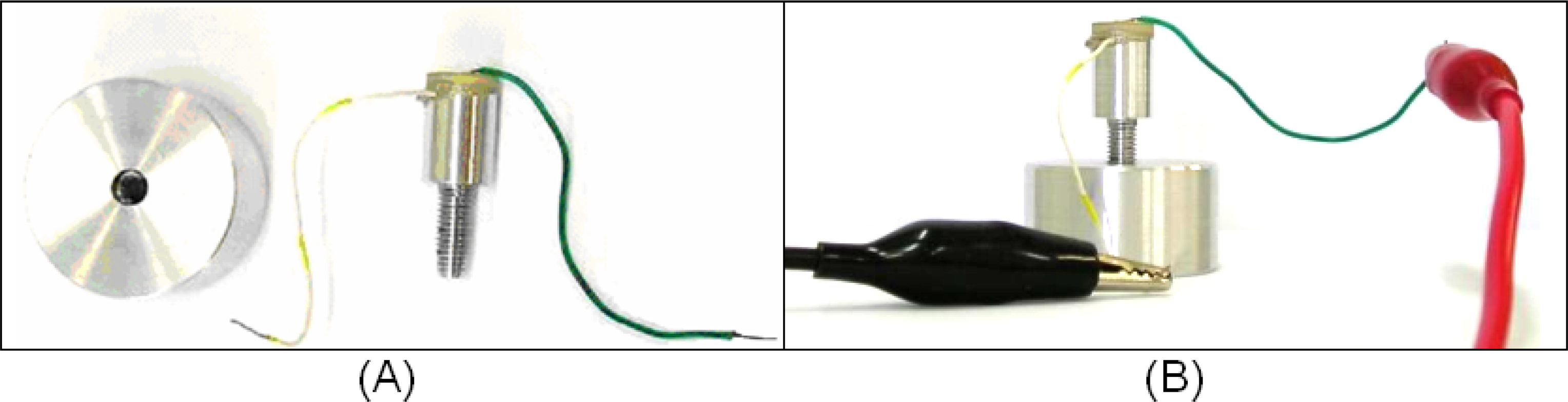
It is known from the literature that the acoustic field is more intense in the direction of the axis of its source [19]; therefore, the experiment aimed to analyze the ultrasonic propagation along a waveguide to ascertain if different levels of lateral attachment would lead to different levels of signal in a ceramic receptor. To verify this possibility, we built a 26-mm-long aluminum waveguide, 13 mm of which consisted of a screw with an external diameter of 5.0 mm. The other 13 mm consisted of a 10-mm diameter cylinder. A PZT piezoelectric ceramic specified as suitable for low-intensity ultrasound transducers (American Piezo, material 855) with a central frequency of 1MHz was glued to the top of the cylindrical part. Both ceramic faces were already coated with conductive electrodes. To facilitate the application of an electrical stimulus to the ceramic, a metal wire was glued to the top face of the ceramic and another to the cylindrical part of the aluminum waveguide, as indicated in Fig. 3 (A). The ceramic was pasted onto the waveguide and the metal wires onto the electrodes using conductive CW2400 epoxy (Chemtronics, CircuitWorks®).
A 3.1-cm diameter, 2.7-cm tall aluminum block was pierced through its full depth and a spiral helix was cut into its inner surface, producing kind of a hollow nut into which the screw part of the aluminum waveguide could be fitted (Fig.3(A)). The absence of contact at the base of the waveguide would render the detection of lateral ultrasound transmission more accurate.
The experiment also involved the construction of an electronic circuit to generate an electric pulse to stimulate the ceramic. The circuit was fed with an alternate square-wave voltage, with amplitude of 5 volts and duration of 10 μs. The electrical pulse caused the ceramic to vibrate, thereby propagating the ultrasonic waves through the aluminum structure.
The ceramic of the aluminum waveguide was excited with an electric pulse and its vibration generated an ultrasonic wave that propagated through the waveguide. The signal reflected on the boundaries of the tool would return to the ceramic, which would work as both source and detector of the device. This procedure was conducted with the aluminum waveguide surrounded by air and also attached to the aluminum block, as indicated in Fig. 3(B). The levels of attachment at which the measurements were taken were 6.4 mm, 8.8 mm and 12 mm of screw contact, and the signals detected at each level of attachment were compared. It is important that the waveguide and implant are made of the same material to minimize reflections due to differences in impedance; aluminum was used because it is cheaper and easier to work with than titanium. To ensure good mechanical coupling between the two parts, the screw was wrapped in aluminum foil. This experiment was repeated seven times.
3. Results
Figs. 4, 5, 6 and 7 illustrate the onset of ultrasonic propagation through the structures used in the initial simulations.
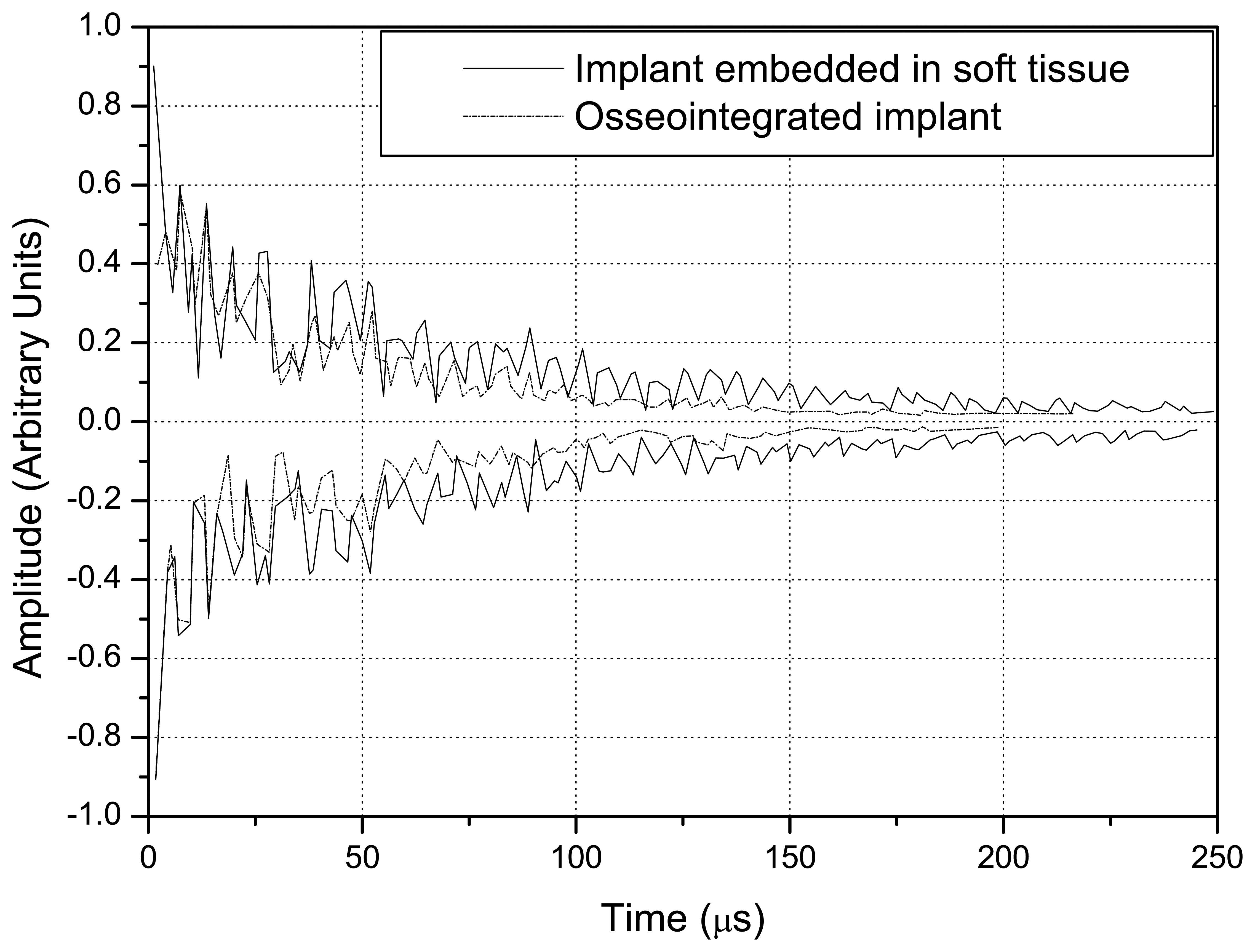
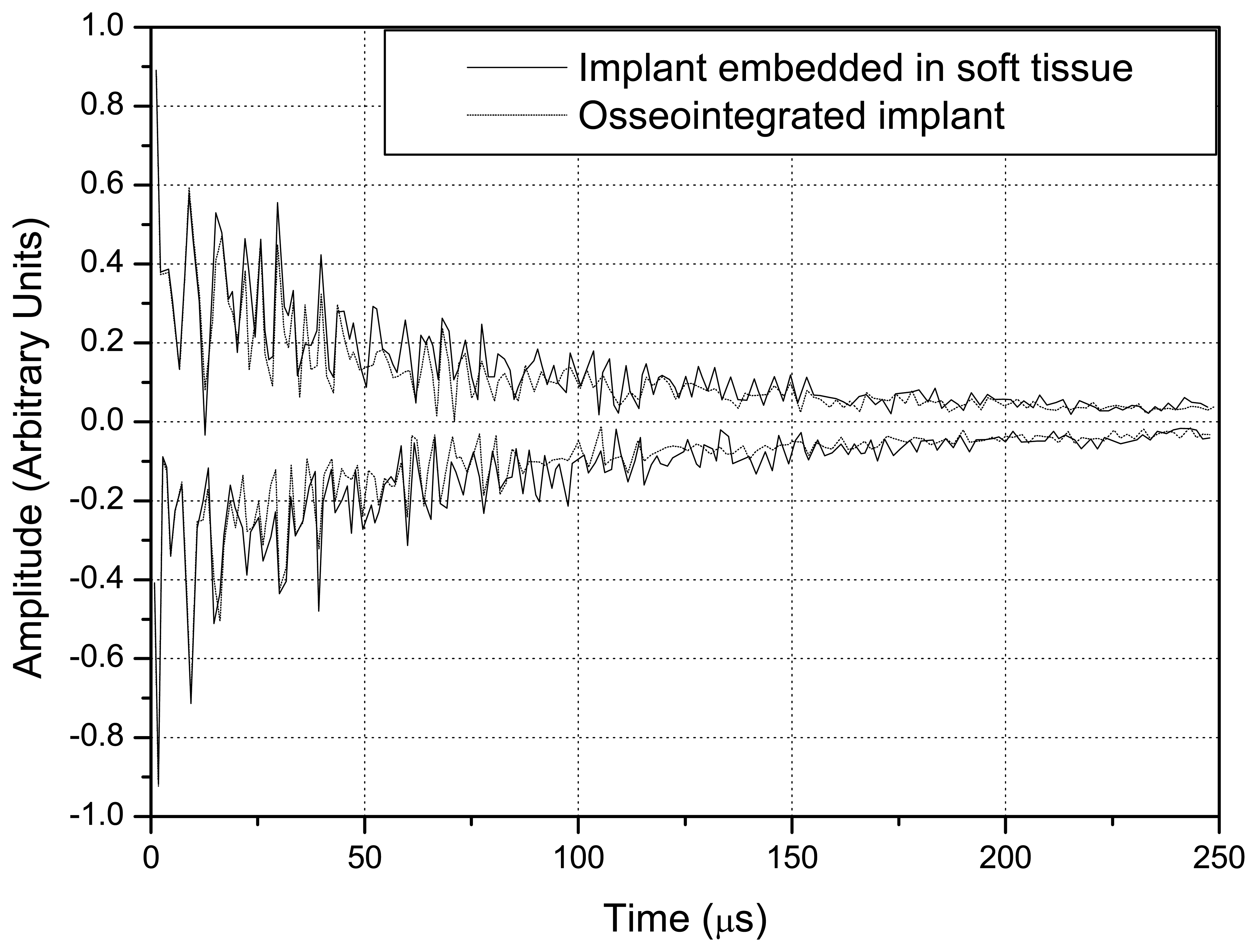
The positive and negative peaks of the detected signals were used to construct envelope curves. The solid lines correspond to implant embedded in soft tissue, whereas the dotted lines refer to the osseointegrated implant. Fig. 8 shows the signals obtained with the step-shaped waveguide, while Fig. 9 indicates those obtained with the conical waveguide.
A comparison of Figs. 8 and 9 indicates that the difference in the amplitude of the signals obtained with the implant embedded in soft tissue and in completely osseointegrated tissue was greater than with the step-shaped waveguide, and that this difference increased over time. Fig. 10 illustrates the energies that returned to the source in each situation from 0 to 250 μs, which were calculated from the signals.
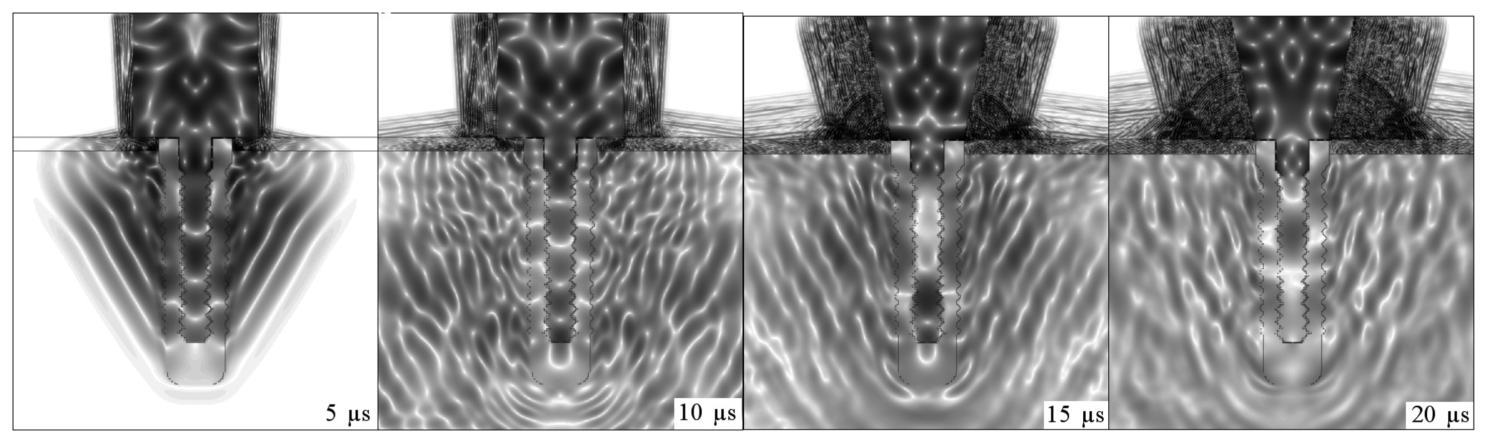
Fig. 11 depicts the propagation of ultrasound in an intermediate stage of the osseointegration process (Fig.2(A)).
Fig. 12 illustrates the energies calculated from the signals detected for an implant surrounded by soft tissue, embedded in three different mixtures of soft tissue and bone, with increasing bone concentrations and complete osseointegration.
When this experiment was implemented, the signal that reached the ceramic as a function of time revealed that the deeper the attachment the shorter the signal's amplitude. The area of the modulus of each received signal was calculated to better distinguish these variations with depth. The graph in Fig. 13 plots the average energies of the signals detected by the ceramic, which were constructed from the data obtained from seven repetitions of the experiment. The average energy values (E̅) were inserted into an exponential relation (k · exp(E̅)) to facilitate the distinction between different levels of attachment. The value of k was adjusted so the average energy in the condition of the implant embedded in soft tissue was equal to one.
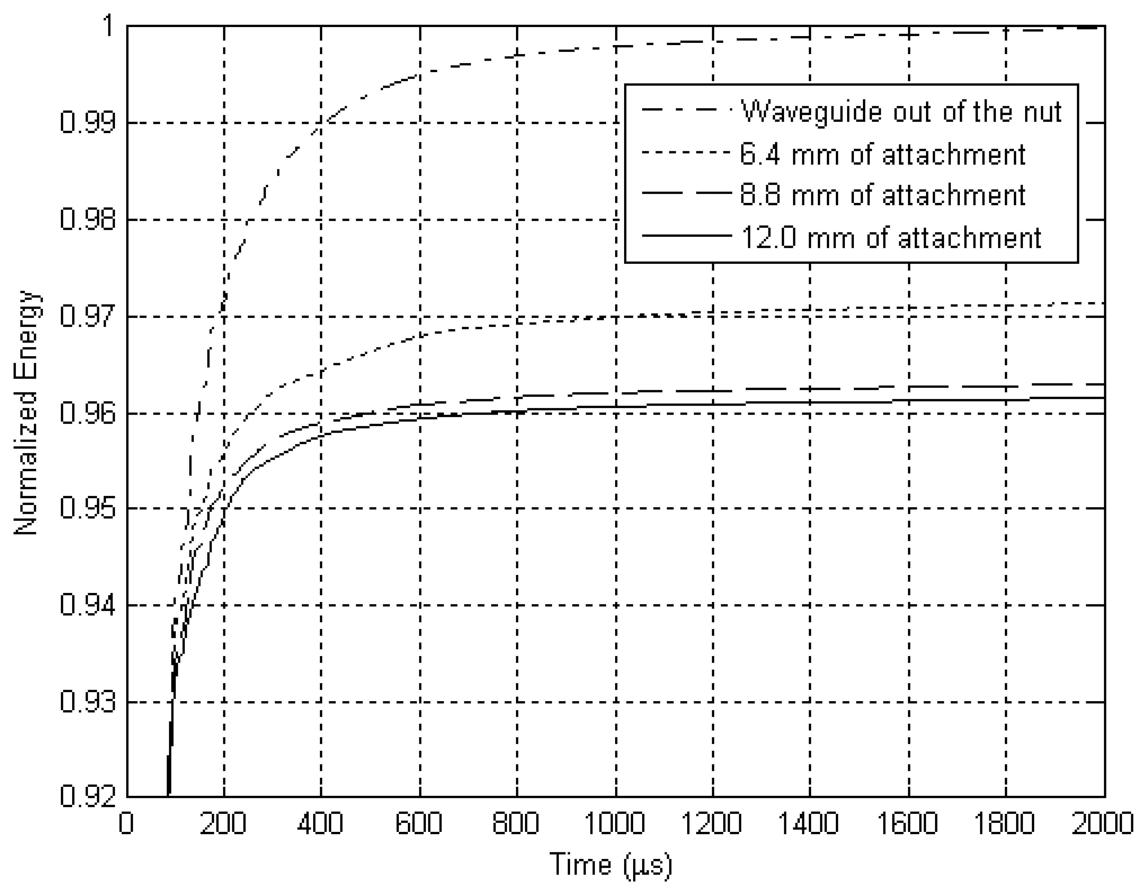
The resulting signal was added cumulatively and the sum was also normalized, as shown in Fig. 14.
4. Discussion
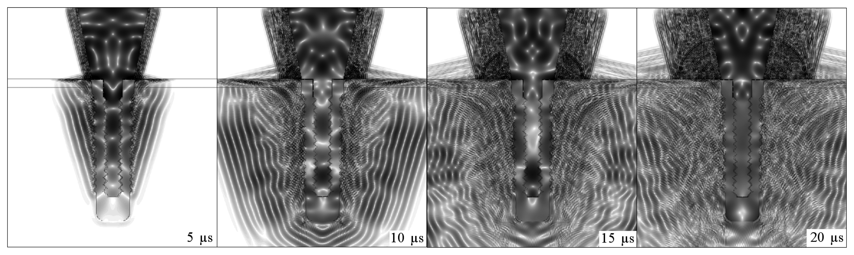
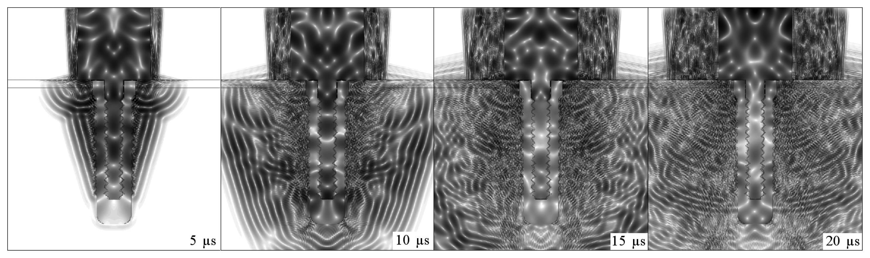
The sequences of dark and light regions which can be seen in Figs. 4, 5, 6 and 7 represent the acoustic wave propagation in which regions of compression and rarefaction are alternated. In these figures, the simulations of conical and step-shaped waveguides indicate that ultrasound propagates more slowly in soft tissue than in bone tissue, regardless of the waveguide geometry. This can be inferred from the distance the ultrasound waves reach after 5 μs and 10 μs of propagation, which is greater in the completely osseointegrated implant. Furthermore, ultrasound reflects more intensely at the titanium-soft tissue interface, where the acoustic impedance is greater (ZTi= 27.33MRayl, ZSoftTissue = 1.67MRayl) than in the titanium-bone tissue interface (ZBoneTissue = 5.37MRayl).
The overlap of the signals detected in the simulation of the implant embedded in soft tissue and in the completely osseointegrated implant indicated that the step-shaped waveguide was more sensitive in detecting changes in the surrounding media. Since the ultrasonic tool for monitoring the osseointegration process is based on the detection of differences in energy transmitted by the implant to the surrounding media, according to changes in its composition, the values of reflected energy were calculated by integrating the square of the modulus of the signals from 0 to 250 μs. This further facilitated the distinction between the signals produced by different waveguide geometries, and clearly indicated the greater sensitivity of step-shaped waveguide.
It was therefore decided to continue using the step-shaped waveguide in this research due to its greater sensitivity in the initial simulations. An intermediate situation was simulated in which the implant was embedded in a mixture of soft tissue and bone. The signal obtained in this situation had an intermediate energy which was lower than that obtained when the implant was surrounded by soft tissue and greater than that emitted by a completely osseointegrated implant. This comparison is shown in Fig. 11.
Simulations of an aluminum waveguide attached at different levels to an aluminum block were conducted to check if the ultrasound transmission through a lateral attachment would suffice to distinguish variations in the level of attachment. These simulations were then also tested experimentally.
The experiment conducted here had some aspects in common with the experiments made to validate the RFA analysis [2], in which the stiffness of implant fixtures mounted in an aluminum block with different heights of the fixture left exposed were measured by attaching a transducer to each implant. Instead of using a polymeric resin to attach the implant to the aluminum block, aluminum foil was used to improve the mechanical attachment of the waveguide to the nut without creating discontinuities of acoustic impedance between the parts. However, the variable mechanical contact established in the experiment due to the arbitrary addition of aluminum foil to the attachment could have led to imprecise results. We believe that this would not be a problem in real situations, since osseointegration involves the intimate and functional attachment of the bone tissue to the titanium implant.
Figs. 13 and 14 depict the results obtained experimentally with an aluminum waveguide and an aluminum nut. The differences in energy detected between the various levels of attachment were distinguished with the use of an exponential relation. A cumulative sum of the energy detected is presented in Fig. 14, which shows the reflected energy tends to stabilize over time. Parts of the energy of the ultrasonic pulse that is launched inside the titanium structure by the source are transmitted to the surrounding media each time it reaches an interface, tending to cancel the energy in the waveguide and implant.
The results obtained from the simulation of the osseointegration process and experimentally with the aluminum waveguide suggest that the reflected energy decreases linearly as the level of attachment increases.
5. Conclusions
Micromotion at the interface has already been shown to influence tissue differentiation and excessive micromotion compromises implant osseointegration, since it prevents contact between the bone and the implant surface. [5, 6] The use of an ultrasonic tool would avoid problems in the osseointegration process resulting from mechanical micromotions. These simulations revealed that differences in the detected signals resulting from changes in the surrounding media can be better distinguished by comparing the energy values corresponding to each signal. Simulations with the implant embedded in soft tissue and in bone suggested that the energy value of the detected signals is correlated linearly to the level of osseointegration. This behavior was also observed in the experiment with the aluminum waveguide, in which the detected energy decreased linearly as the waveguide's contact area with the nut increased.
Although ultrasound is a longitudinal signal, its original form can be modified during its propagation. The above described experiment revealed that the ultrasound launched in the aluminum waveguide was transmitted to the aluminum block when waveguide and block were coupled mechanically to each other. The energy transmitted to the aluminum block was a function of the insertion height; in other words, it was confirmed that the transmission of energy was influenced by the contact area. The experiments showed that this transmission is strong enough to produce detectable differences according to the level of attachment.
The next step is to determine the relation between the reflected energy and the osseointegrated area, which is the principle of the ultrasonic tool for monitoring the osseointegration of dental implants. Then, it'll be necessary to reduce the dimensions of the waveguide and conduct more experiments to validate it as a clinical tool.
References
- Olivé, J.; Aparicio, C. Periotest method as a measure of osseointegrated oral implant stability. International Journal of Oral & Maxillofacial Implants 1990, 5, 390–400. [Google Scholar]
- Meredith, N.; Alleyne, D.; Cawley, P. Quantitative determination of the stability of the implant-tissue interface using resonance frequency analysis. Clinical Oral Implants Research 1996, 7, 261–267. [Google Scholar]
- Aparicio, C.; Lang, N. P.; Rangert, B. Validity and clinical significance of biomechanical testing of implant/bone interface. Clinical Oral Implants Research 2006, 17 Suppl. 2, 2–7. [Google Scholar]
- Ersanli, S.; Karabuda, C.; Beck, F.; Leblebicioglu, B. Resonance frequency analysis of one-stage dental implant stability during the osseointegration period. Journal of Periodontology 2005, 76, 1066–1071. [Google Scholar]
- Duyck, J.; Vandamme, K.; Geris, L.; VanOosterwyck, H.; DeCooman, M.; Vandersloten, J.; Puers, R.; Naert, I. The influence of micro-motion on the tissue differentiation around immediately loaded cylindrical turned titanium implants. Archives of Oral Biology 2006, 51, 1–9. [Google Scholar]
- Szmukler-Moncler, S.; Salama, H.; Reingewirtz, Y.; Dubruille, J. H. Timing of loading and effect of micromotion on bone-dental implant interface: Review of experimental literature. Journal of Biomedical Materials Research 1998, 43, 192–203. [Google Scholar]
- Szmuker-Moncler, S.; Piattelli, A.; Favero, G. A.; Dubruille, J. H. Considerations preliminary to the application of early and immediate loading protocols in dental implantology. Clinical Oral Implants Research 2000, 11, 12–25. [Google Scholar]
- Huiskes, R.; Ruimerman, R.; Lenthe, H.; Janssen, J. D. Effects of mechanical forces on maintenance and adaptation of form in trabecular bone. Nature 2000, 405, 704–706. [Google Scholar]
- Warden, S. J.; Bennell, K. L.; McMeeken, J. M.; Wark, J. D. Acceleration of fresh fracture repair using the sonic accelerated fracture healing system (SAFHS): A review. Calcified Tissue International 2000, 66, 157–163. [Google Scholar]
- Rubin, C.; Bolander, M.; Ryaby, J. P.; Hadjiargyrou, M. The use of low-intensity ultrasound to accelerate the healing of fractures. Journal of Bone and Joint Surgery 2001, 83A, 259–270. [Google Scholar]
- Duarte, L. R. Estimulação ultra-sônica da consolidação de fraturas ósseas. 1983. BR PI 8107560. [Google Scholar]
- Heckman, J. D.; Ryaby, J. P.; McCabe, J.; Frey, J. J.; Kilcoyne, R. F. Acceleration of tibial fracture-healing by non-invasive, low-intensity pulsed ultrasound. Journal of Bone and Joint Surgery 1994, 76, 26–34. [Google Scholar]
- Kristiansen, T.K.; Ryaby, J. P.; McCabe, J.; Frey, J. J.; Roe, L. R. Accelerated healing of distal radial fractures with the use of specific, low-intensity ultrasound. A multicenter prospective, randomized, double-blind, placebo-controlled study. Journal of Bone and Joint Surgery 1997, 79A, 961–973. [Google Scholar]
- Winder, A. A.; Talish, R. J.; Ryaby, J. P. Sistema acústico para a terapia de fratura óssea. Exogen Inc 1999. BR PI 9510480-1 A. [Google Scholar]
- Tanzer, M.; Kantor, S.; Bobyn, J. D. Enhancement of bone growth into porous intramedullary implants using non-invasive low intensity ultrasound. Journal of Orthopaedic Research 2001, 19, 195–199. [Google Scholar]
- Hantes, M. E.; Mayrodontidis, A. N.; Zalavras, C. G.; Karantanas, A. H.; Karachalios, T.; Malizos, K. N. Low-intensity transosseous ultrasound accelerates osteotomy healing in a sheep fracture model. Journal of Bone Joint Surgery 2004, 86A, 2275–2282. [Google Scholar]
- Malizos, K. N.; Hantes, M. E.; Protopappas, V.; Papachristos, A. Low-intensity pulsed ultrasound for bone healing: An overview. Injury, International Journal of the Care of the Injured 2006, 37S, S56–S62. [Google Scholar]
- Schechter, R. S.; Chaskelis, H. H.; Mignogna, R. B.; Delsanto, P. P. Real-time parallel computation and visualization of ultrasonic pulses in solids. Science 1994, 265, 1188–1192. [Google Scholar]
- Redwood, M. Mechanical Waveguides: The propagation of acoustic and ultrasonic waves in fluids and solids with boundaries.; Pergamon Press, 1960. [Google Scholar]
Figure 1.
Dimensions used in the simulations for comparison between the (A) conical and (B) step-shaped titanium waveguides completely attached to titanium implants. The surrounding media were air in the region above the implant and around the “head” of the waveguide, soft tissue around 2 mm of the neck of the implant, and soft tissue around the rest of the implant, followed by bone tissue for comparison.
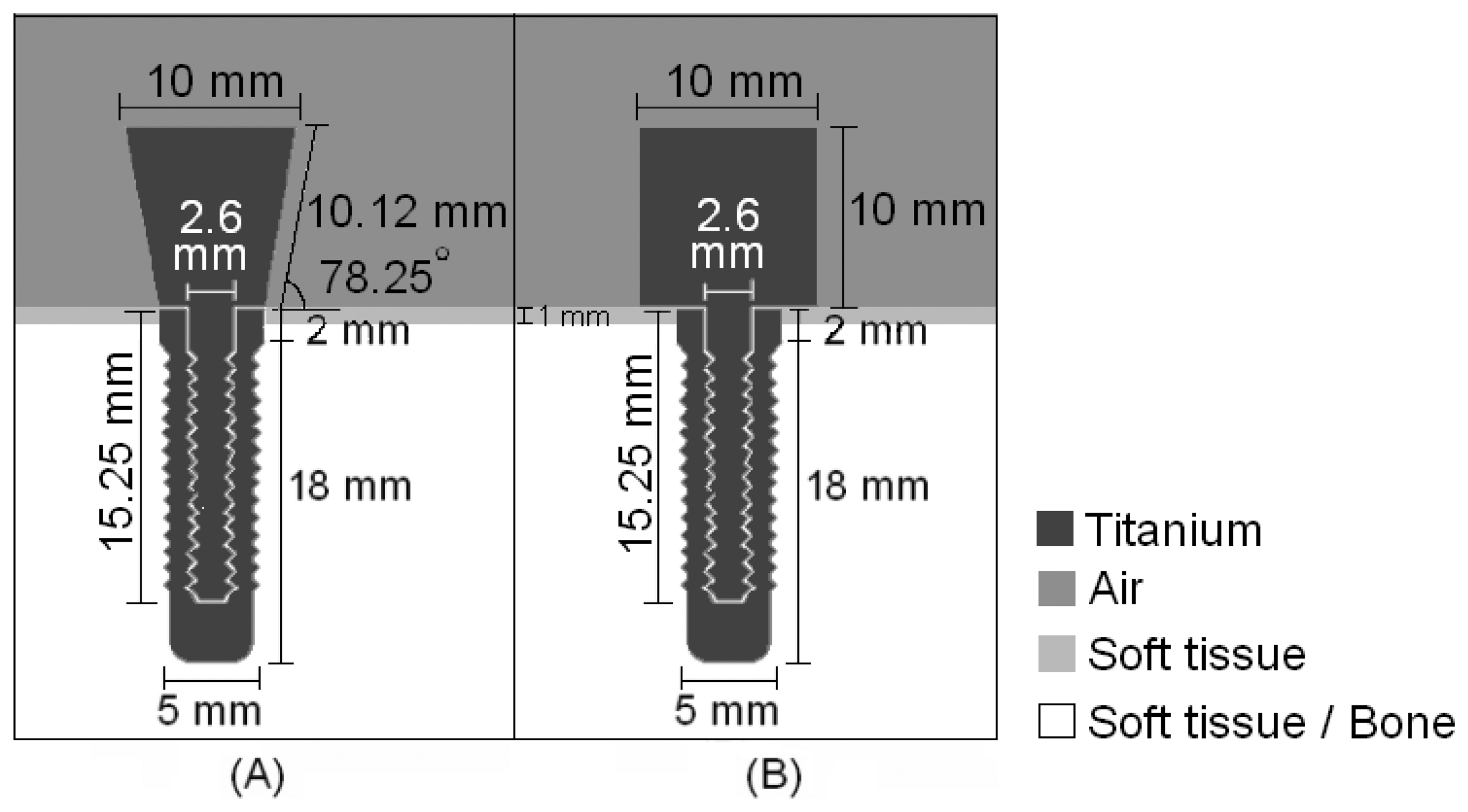
Figure 2.
Configurations used in simulations of intermediate stages of the osseointegration process. The concentration of bone tissue increased from (A) to (C).
Figure 2.
Configurations used in simulations of intermediate stages of the osseointegration process. The concentration of bone tissue increased from (A) to (C).

Figure 3.
(A) Aluminum block and aluminum waveguide built for the experiment. (B) Experiment conducted with different levels of attachment of the aluminum waveguide in the aluminum block.
Figure 3.
(A) Aluminum block and aluminum waveguide built for the experiment. (B) Experiment conducted with different levels of attachment of the aluminum waveguide in the aluminum block.
Figure 4.
Low-intensity pulsed ultrasound propagation through a conical titanium waveguide attached to an implant of the same material surrounded by soft tissue.
Figure 4.
Low-intensity pulsed ultrasound propagation through a conical titanium waveguide attached to an implant of the same material surrounded by soft tissue.

Figure 5.
Low-intensity pulsed ultrasound propagation through a conical titanium waveguide attached to an osseointegrated implant of the same material.
Figure 5.
Low-intensity pulsed ultrasound propagation through a conical titanium waveguide attached to an osseointegrated implant of the same material.
Figure 6.
Low-intensity pulsed ultrasound propagation through a step-shaped titanium waveguide attached to an implant of the same material surrounded by soft tissue.
Figure 6.
Low-intensity pulsed ultrasound propagation through a step-shaped titanium waveguide attached to an implant of the same material surrounded by soft tissue.

Figure 7.
Low-intensity pulsed ultrasound propagation through a step-shaped titanium waveguide attached to an osseointegrated implant of the same material.
Figure 7.
Low-intensity pulsed ultrasound propagation through a step-shaped titanium waveguide attached to an osseointegrated implant of the same material.

Figure 8.
Overlap of envelopes of the signals detected in the simulation of the step-shaped waveguide, with the implant surrounded by soft tissue and the osseointegrated implant.
Figure 8.
Overlap of envelopes of the signals detected in the simulation of the step-shaped waveguide, with the implant surrounded by soft tissue and the osseointegrated implant.

Figure 9.
Overlap of envelopes of the signals detected on the simulation of the conic waveguide, with the implant surrounded by soft tissue and the osseointegrated implant.
Figure 9.
Overlap of envelopes of the signals detected on the simulation of the conic waveguide, with the implant surrounded by soft tissue and the osseointegrated implant.

Figure 10.
Energy of the signals detected using a conical and a step-shaped waveguide in the simulation of an implant embedded in soft tissue (1 and 3) and completely osseointegrated (2 and 4).
Figure 10.
Energy of the signals detected using a conical and a step-shaped waveguide in the simulation of an implant embedded in soft tissue (1 and 3) and completely osseointegrated (2 and 4).

Figure 11.
Low-intensity pulsed ultrasound propagation through a step-shaped titanium waveguide attached to an implant of the same material surrounded by a combination of soft tissue and bone.
Figure 11.
Low-intensity pulsed ultrasound propagation through a step-shaped titanium waveguide attached to an implant of the same material surrounded by a combination of soft tissue and bone.
Figure 12.
Energy of signals detected using a step-shaped waveguide in the simulation of an implant: 1) surrounded by soft tissue; 2-4) surrounded by a mixture of soft tissue and bone, with increasing concentration of bone tissue; 3) completely osseointegrated.
Figure 12.
Energy of signals detected using a step-shaped waveguide in the simulation of an implant: 1) surrounded by soft tissue; 2-4) surrounded by a mixture of soft tissue and bone, with increasing concentration of bone tissue; 3) completely osseointegrated.
Figure 13.
Normalized exponential of the average energies of the signals detected by the ceramic attached to the aluminum step-shaped waveguide, obtained for different levels of attachment: 1) Waveguide out of the nut; 2) 6.4 mm; 3) 8.8 mm; and 4) 12.0 mm of attachment to the aluminum nut. The average energies were obtained from seven repetitions of the experiment.
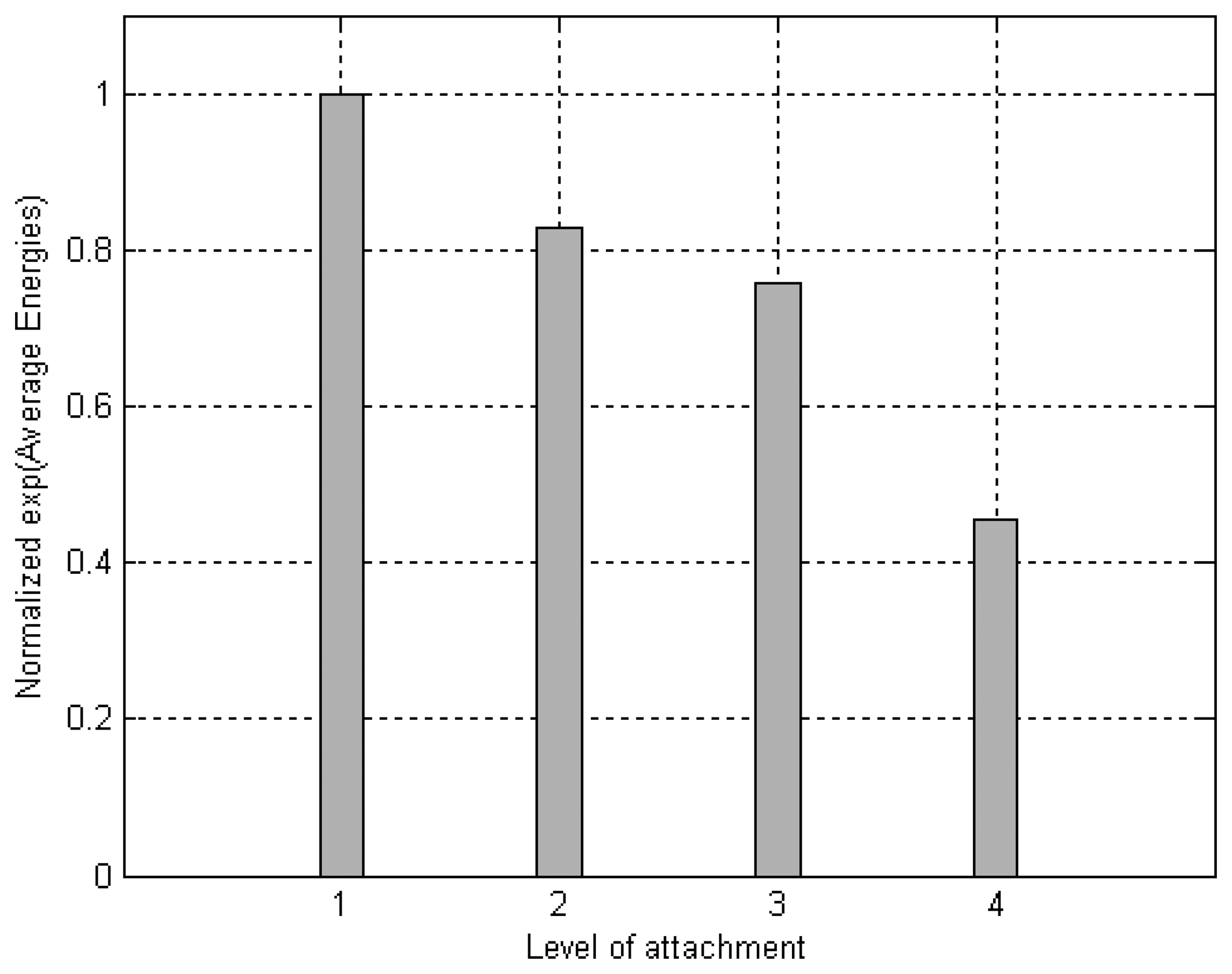
Figure 14.
Cumulative sum of the energy returning to the ceramic, calculated from the median signals of each level of attachment of the aluminum step-shaped waveguide to the aluminum nut.
Figure 14.
Cumulative sum of the energy returning to the ceramic, calculated from the median signals of each level of attachment of the aluminum step-shaped waveguide to the aluminum nut.
© 2007 by MDPI ( http://www.mdpi.org). Reproduction is permitted for noncommercial purposes.
Share and Cite
MDPI and ACS Style
De Almeida, M.S.; Maciel, C.D.; Pereira, J.C. Proposal for an Ultrasonic Tool to Monitor the Osseointegration of Dental Implants. Sensors 2007, 7, 1224-1237. https://doi.org/10.3390/s7071224
AMA Style
De Almeida MS, Maciel CD, Pereira JC. Proposal for an Ultrasonic Tool to Monitor the Osseointegration of Dental Implants. Sensors. 2007; 7(7):1224-1237. https://doi.org/10.3390/s7071224
Chicago/Turabian StyleDe Almeida, Marina Storani, Carlos Dias Maciel, and José Carlos Pereira. 2007. "Proposal for an Ultrasonic Tool to Monitor the Osseointegration of Dental Implants" Sensors 7, no. 7: 1224-1237. https://doi.org/10.3390/s7071224