Software and Equipment for Remote Testing of Sensors

Faculty of Electrical Engineering and Computer Science, Smetanova 17, Maribor, Slovenia
*
Author to whom correspondence should be addressed.
Sensors 2007, 7(7), 1306-1316; https://doi.org/10.3390/s7071306
Submission received: 26 April 2007
/
Accepted: 19 July 2007
/
Published: 20 July 2007
Abstract
:An improved approach for remote testing of elements and systems is presented in this article. To ensure high reliability of products, tests must be done in the production phase to detect possible errors in working mode. Because environmental testing involves long-term processes the possibility of remote observation and remote controlling of tests is very useful solution. The concept is to connect the testing chamber with a personal computer, create a reliable driver and control it remotely over the local network or Internet from other client. It is designed for performing tests on wide area of sensors and sensor based systems.
1. Introduction
Reliability of developed products is important for the producer and also for the end-user of products. The number of methods and standards to determine reliability have increased noticeably. The tendency towards reliability assurance is also greater. As sensors are installed and in use in all environments and industrial areas, so the expected reliability in operating mode is very high. Moreover, market competition is rising, which forces producers to ensure high reliability for their products. Planning reliability, testing of prototypes and final products is an essential part of the planning and production process. Planning the reliability must be well based in the beginning. The possible failure modes have to be identified and some standard methods can be used, for example FMEA (Failure Mode and Effects Analysis). When product is in a phase where it is to be tested in operation mode, accelerated tests have to be developed and verified. Here, environmental based testing methods are stressed: Highly Accelerated Life Testing (HALT), Highly Accelerated Stress Screening (HASS), Environmental Stress Screening (ESS), Burn-in and Standard based methods. Most of the testing methods require long-term exposure of elements and systems to various changing parameters [1-3].
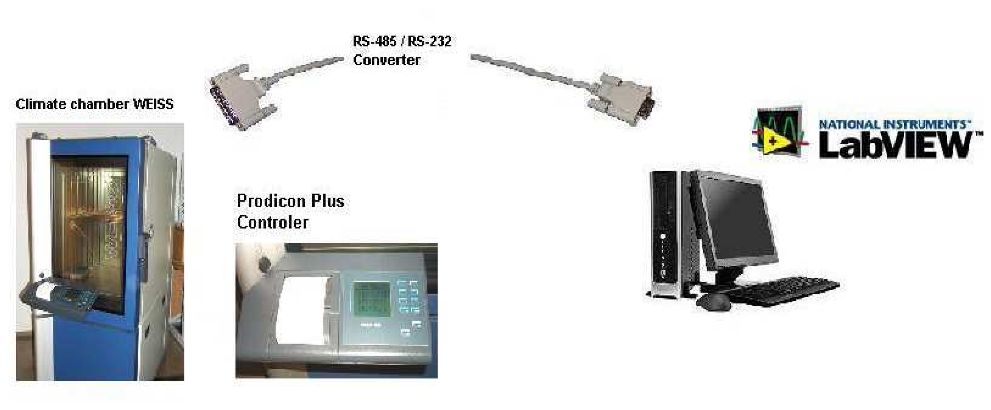
There are a lot of testing chambers on the market, which provide simulation of different environments and enable reliability testing. Some of the providers are: Weiss Technik, TPS - Thermal Product Solutions, Russels Technical Products, Hastest Solutions, Inc. and others. Their fields of interest are in improving the performance of the chambers. Testing chambers have controllers situated on the chamber or they offer the possibility of connection with personal computer. This requires that user set parameters at the place where tests are being run, but when tests are performed for a long time, remote control comes into use and makes testing efficient, economical and saves time by observing and controlling tests remotely. The main components of the discussed system are presented in Figure 1. Remote control can be established from any personal computer connected to a network (Internet or local network).
Driver and application (the combination is called a Virtual Instrument) were developed to provide remote connection to the chambers and subsequent remote control and supervision of the conditions in the chamber. A Virtual Instrument connects server and controller situated on the chamber. Sent packages of data are generated with the program for testing. From any other client computer, which is in the network, connection to a chamber can be established using network connections. It presents an approach for providing suitable environments for testing sensors and sensor related systems. Remote laboratories have become a frequent praxis as an application, from which devices can be controlled over local networks or the Internet [1, 4].
2. Methods for remote testing inside the climate chamber
2.1. Environmental stress screening
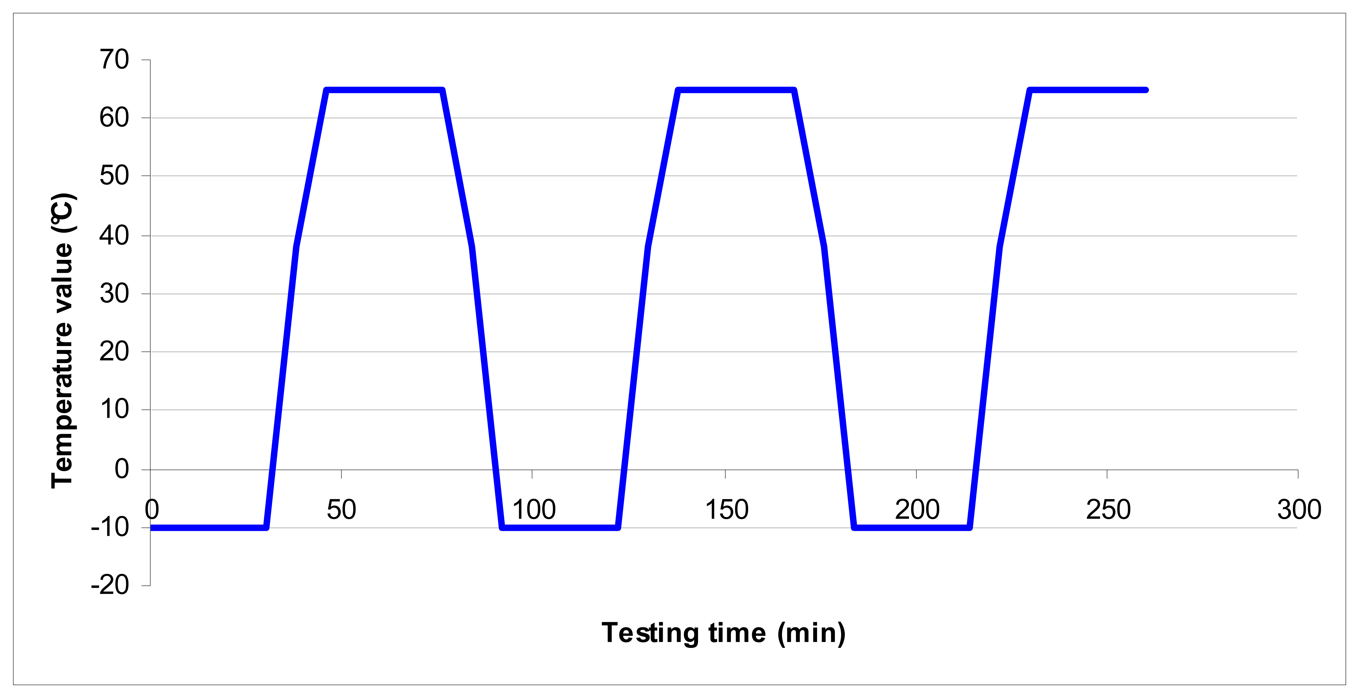
Environmental stress screening (ESS) is a combination of environmental parameters in order to provide simulation of the working environment of the product. It is designed to accelerate the failure of faulty products, which are in operating mode and are being monitored. With these tests critical conditions, to which element(s) can be exposed to, are simulated. In Figure 2 there is an example of ESS testing program [2, 3].
2.2. Standard IEC (Automatic mode)
2.3. HALT & HASS
HALT (Highly Accelerated Life Testing) is a testing method for providing higher reliability and quality of electromechanical or electronic systems. It is usually used during the early phase of development of the system. Its goal is to expose the working system to temperature cycles and vibration limits. Systems also operate beyond their electrical limit values. The purpose of working under limited values is to break down the system. The elements that are damaged need to be upgraded or reinforced in order to provide greater product reliability. The HALT process continues with higher limited values to break the product again or to reach the limits of the testing chamber. This type of testing can make products very robust, but on the other hand, HALT testing can make development of the systems quite expensive [2, 3, 5-7].
In addition to HALT there is also HASS (Highly Accelerated Stress Screening) testing. It is a production stress testing of the elements or the system to find possible errors before products are marketed. Tests are a combination of modifications of vibration, temperature and operating specifications. Systems or elements are run in operation mode. Here the purpose is that no part of the system breaks, so the limits are taken from HALT testing results that were analyzed. If some changes have been made in design phase, HASS testing should be repeated. In case of some major changes, both HALT and HASS should be repeated [5, 7-10].
2.4. BURN-IN TEST
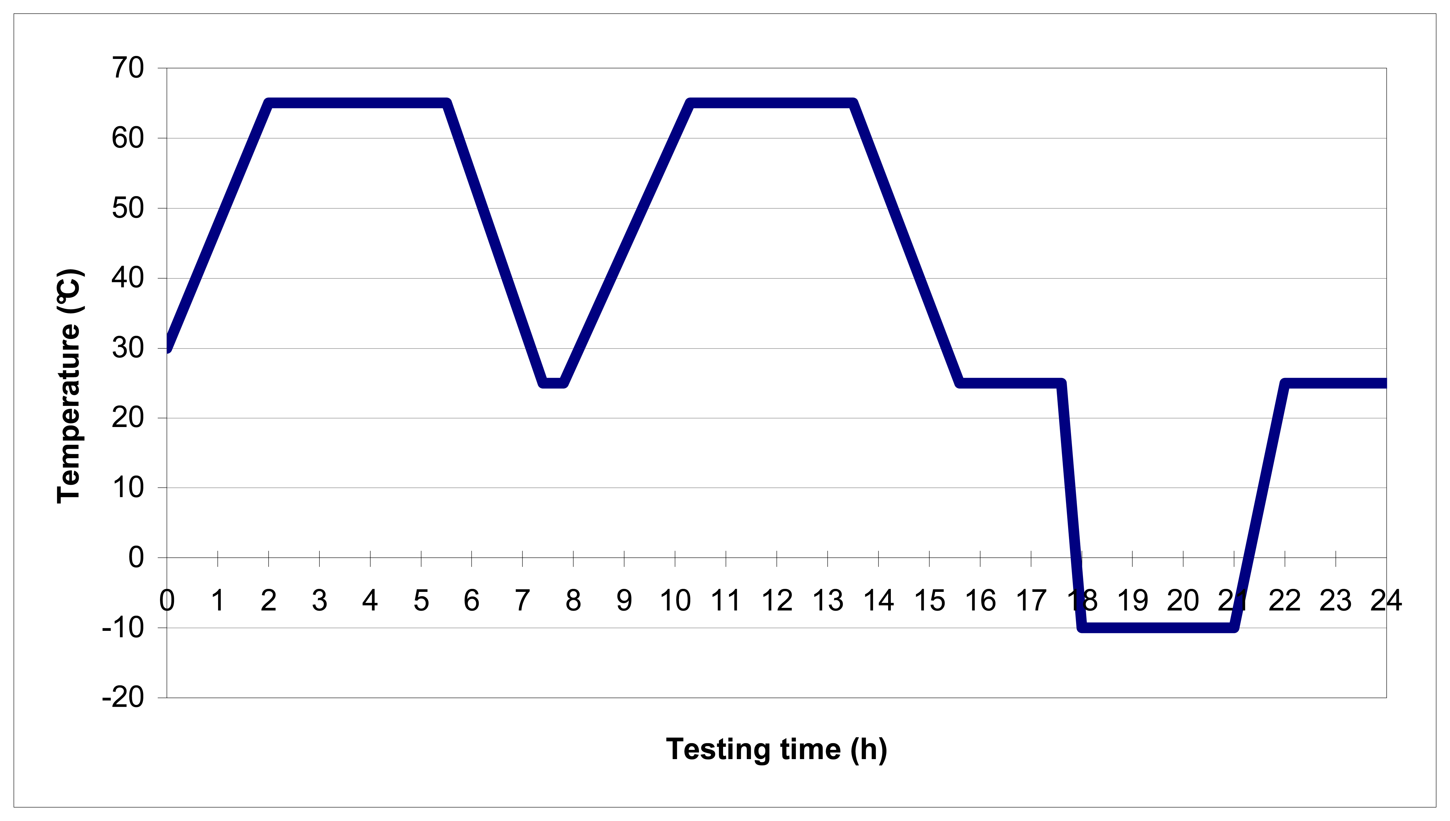
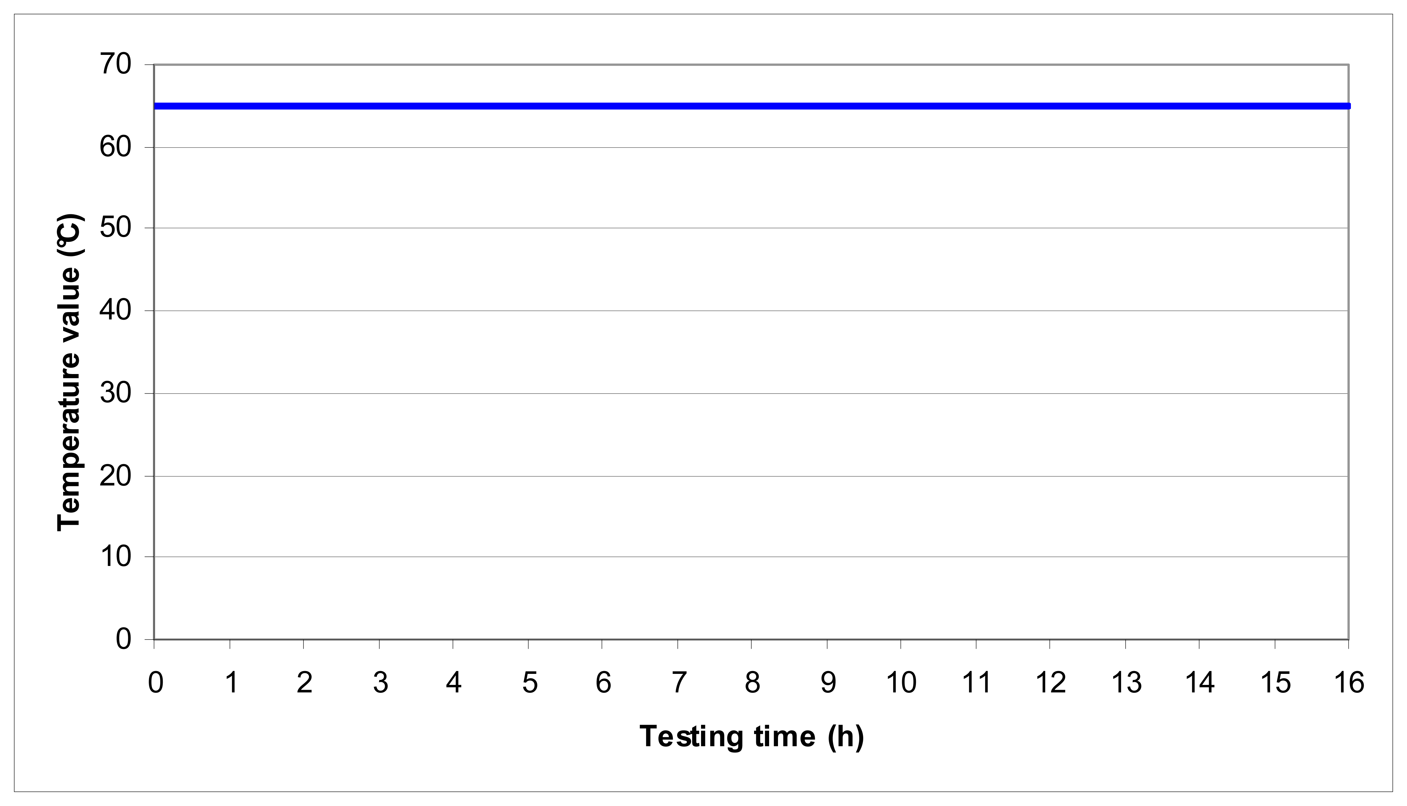
Burn-in screening is a testing method to provide higher product reliability. The product operates under higher conditions, which are: increased maximum voltage, increased temperature, humidity and vibration for defined period of time. In Figure 5 an example of exposure to high temperature values is shown. Criteria of the screening are determined through a series of engineering tests to get the most effective burn-in conditions. Purpose of this test is to find possible errors before product is placed on the market. It is based on the “bath-tub” curve of the lifetime of the product, where it can be seen that majority of failures occur in the early phase in the life of the product. Under these conditions ageing of the elements and systems is accelerated to get through period of early failures [5, 7-11].
3. Virtual instrument (VI)
3.1 LabVIEW with Web Publishing Tool
Usually commercial software provided with climate testing hardware doesn't contain tools for remote testing, which are very useful in long-term testing processes. In this case a chamber with a personal computer was located in the testing laboratory.
A testing application named Virtual Instrument (VI) was developed using the LabVIEW software. LabVIEW is graphical programming software language for instrumentation, data-acquisition, analysis, automation, control and communication developed by National Instruments on a variety of platforms including Microsoft Windows, UNIX, Linux, and Mac OS. The latest version is LabVIEW release 8.2.
In LabVIEW there is a function called Web Publishing Tool that creates .html files and the front panel of the virtual instrument is embedded within. It creates a built in Web server. The IP address or the name of the client computer must have enabled access to the server. The published VI must be visible to other clients. When the web page is downloaded, a client can sent a Request for Control. When the server approves a request, the remote user gains control of the interface. The software uses Data Socket technology with ActiveX controls, which first downloads an .html page and refreshes only data that has been changed, so it works reasonably fast, even with low download rates. On the client computer LabVIEW or the Run-Time Engine driver corresponding to the same version as the original VI must be installed, which can be downloaded for free from web page of National Instruments [4].
3.2 Data transfer
Using this Virtual Instrument data is transferred from a computer over RS-232/RS-485 to a Prodicon Plus controller located on the climate chamber. Serial communication is executed with data packages. The data package includes start bits, message, Check Sum bits for verification and stop bits. The receiver receivesdata bit by bit and waits for a Stop bit for the end of message. To verify the correctness of the data, a Check Sum number is calculated and compared to the value received. Here an example of sent message to the chamber is given: 2HEX 1 T123.4 F56 P1 T124.4 $99 T123.4 F56 R0000000000000000 CCHEX 3HEX. An explanation of the values in the data package follows: [2]HEX – Start bit in Hexadecimal; [1] – Automatic Mode; [T123.4] - Value of actual temperature; [F56] – Value of actual relative humidity in [%]; [P1] – Printer On; [T124.4] – Value of actual temperature on custom added sensor; [$99] – Error Code; [T123.4] – Value of set Temperature; [F56] – Value of set humidity in [%]; [R0000000000000000] – Values of 16 free digital channels; [CC] – Calculated Check Sum Value in Hexadecimal; [3] – Stop bit in Hexadecimal.
An RS-485 interface connector is on the chamber. This is the fastest connection that this type of chamber provides. The chamber that was used was a WEISS 300/40 climate chamber for environmental simulations produced by Weiss Umwelttechnik GmbH. Advanced and newer climate chambers provide more widely used and faster interfaces. In that case, the type of connection must be changed in the syntax, which is quickly solved with LabVIEW graphical tools.
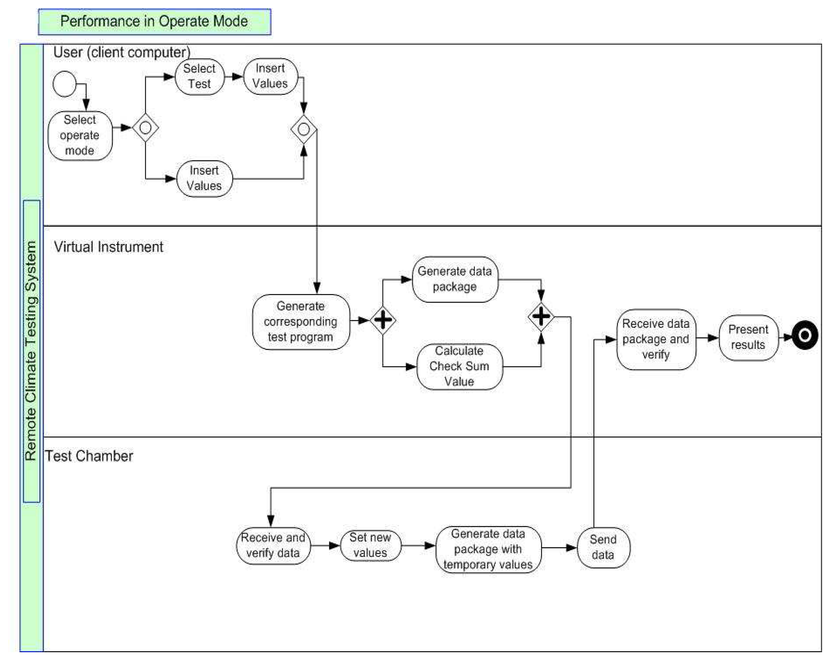
Performance of the system is based on fast and efficient data transfer. VI sends data immediately after receiving command from user interface. In Figure 6 the data transfer and sequence of tasks from user to Test Chamber is briefly presented. Transfer starts with a user command. The user on the client computer selects the mode of operation. Selection of test and limit values must be made. Virtual instrument generates a test program according to inserted and selected values. A data package is formed and sent to the chamber controller, which sets new values or/and sends data package with actual values in the chamber. Virtual instrument receives data, verifies it and presents the results.
3.3 Application
The concept of the software is in the user-friendly interface. The presumption is that a user is acquainted with methods for environmental testing which were described in the previous chapter. The user controls the parameters manually (manual mode), when chamber is working or selects automatic mode and then selects a type of method. The program can be stopped and cancelled at any time. When a program is running, the application can be observed and controlled remotely at all times.
The testing program for contains time periods of temperature and humidity. Limits of parameters of the testing sensor, element or device must be inserted. Based on the limits, the software generates a testing program depending on the selected method. In automatic mode all testing programs are generated by the software. In manual mode a user can insert optional time periods or select some previously saved or already run testing program. Tests are saved in a MySQL database, where they are saved to the corresponding database. Some other databases like MS Access can also be used. Tables contain information of name and date of the test, so searching through database is fast and organized.
User selects automatic mode and than chooses among following tests (Figure 7):
- -
- STANDARDS, which are commonly known for testing and are already saved in database,
- -
- HALT & HASS,
- -
- BURN-IN,
- -
- ESS.
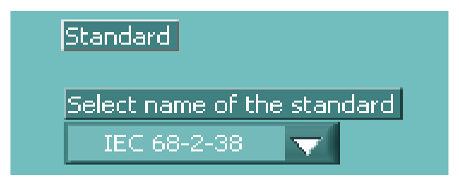
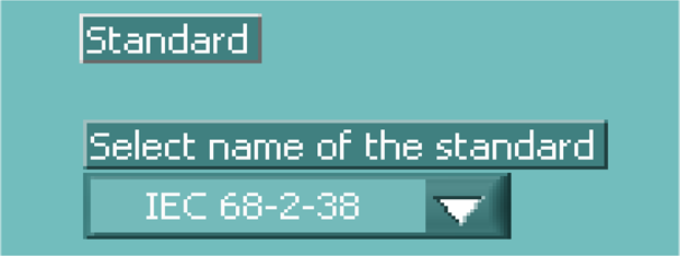
When selecting Standard mode, it displays list of all the saved standards, that user can choose from (Figure 8).
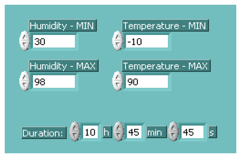
When HALT & HASS, BURN-IN or ESS are selected, the application will generate its own program suitable for the testing object inside the chamber (Figure 9). The user has to insert parameters, which are specifie to the element inside. These are maximum temperature and humidity values, minimum temperature and humidity values and duration of the tests.
In manual mode the user can create his own program. He must insert the name of the new program and intervals with values of temperature, humidity and duration of the interval. A way of reaching the selected temperature and humidity (that is ramp or step) must also be selected. Parameters can be changed online, which means that when selecting manual mode user can change parameters while the chamber is running.
Results of climate conditions inside are displayed on the charts and are presented in next chapter. The system can be modified with some additions like vibration elements for advanced and more accurate testing. Chamber has also some free digital channels to which sensor device or sensor itself can be connected in order to observe the operating components inside the chamber.
4. Experimental results
4.1. Experimental example of remote measurement with Standard IEC
Experiments were done for climate testing and tests were done under program of standard IEC-68-2-38. In this part of the research automatic mode was selected. The selected testing program was the IEC-68-2-38 standard for climate testing of electronic components, which is saved in MySQL database and was previously presented in Figures 3 and 4. This testing program runs for 24 hours. It is evident from the graphs in Figure 10 that the response of temperature and humidity following set parameters that were sent to the chamber.
4.2. Performance
The application and system are designed for reliability testing. It can also be modified by customer requests to satisfy any particular need. Some alternative add-ons can be provided. For example, a user can search through a database for previously done tests or generate and print the report done on that test.
Response of the chamber depends on the chamber characteristics. Following a 30° C to 50° C step change this chamber response time is approximately 20 minutes. To increase relative humidity from 50 % to 80 % around 15 minutes were needed. Climate processes are among the slowest, so the time when the chamber reaches new value depends on the previous state in the chamber, the new value and the characteristics of the chamber.
This approach is suitable to test prototypes. It can be applied to some new products, which are not yet ready for mass production. The basic idea is that now a manufacturer, when developing a sensor based system, can test his product himself. A product can be monitored at all times and various tests can be performed. Resources are needed only for testing expenses and renting a chamber. Technical staff is needed only in case of emergency, which could occur in the working mode of the chamber and it depends on reliability of the chamber itself.
The system must provide high reliability. This is provided mostly with high availability. The chamber must operate the whole time test is running mode in order to make tests accurate. This is guaranteed by the producers of the climate chambers. Availability of connection between remote control and chamber is based on open network connection. If remote connection is lost, tests are normally running, since program is saved in database of the server. Control and observations are interrupted only momentarily. To avoid broken network connections a redundancy of data transfer has to be included in the system configuration.
5. Summary
The main purpose of this article was to present a modified approach to testing, which is a combination of various reliability testing methods, remote control and observation of the tested objects with user-friendly software. These tests can be performed with testing chamber and the described Virtual Instrument. The only limitations are the limits of operation of the tested elements or systems, which are working beyond limited values of the testing chamber. The main advantage of the software is its ability to observe and change settings of the tests remotely from any computer in the network. Even high download rates are not needed. The application works with Data Socket technology, which simplifies live data exchange between computers connected through a network. Even if a remote connection (Internet or local network) breaks, tests are still running in automatic mode inside the chamber, because program has been saved in database on the server computer.
One of the main benefits of providing this kind of environment is the possibility to test a wide range of systems and products inside. For example we can also observe bioprocesses which require long-term exposure to climate change or any other objects that needs to be tested with this approach. All data saved in database can be viewed with the software. A Virtual instrument was created, which is nowadays also a very popular method in education and research for remote laboratory experiments.
References and Notes
- O'Connor, P.D. Practical Reliability Engineering; John Wiley & Sons, Inc.: New York, 2002; p. 360. [Google Scholar]
- Levin, M. A.; Kalal, T. T. Improving Product Reliability; John Wiley & Sons Ltd: London, 2003; pp. 283–296. [Google Scholar]
- Mourad, S.; Zorian, Y. Principles of testing electronic systems; John Wiley & Sons, Inc.: New York, 2000; pp. 261–294. [Google Scholar]
- Bitter, R.; Mohiuddin, T.; Nawrocki, M. LabVIEW Advanced Programming Techniques; CRC Press LLC: New York, 2001; pp. 68–121. [Google Scholar]
- Wasserman, G. S. Reliability verification, Testing, and analysis in engineering design; Marcel Dekker, Inc.: New York, 2003; pp. 253–282. [Google Scholar]
- Feinberg, A. A.; Gibson, G. J. Accelerated Reliability Growth Methodologies and Models. In A volume in honor of Alonzo Clifford Cohen; Balakrishnan, N., Jr., Ed.; CRC Press LLC: USA, 1995; Chapter 12; pp. 219–240. [Google Scholar]
- Wood, N. O. Reliability in design. In A volume in honor of Alonzo Clifford Cohen; Balakrishnan, N., Jr., Ed.; CRC Press LLC: USA, 1995; Chapter 14; pp. 257–266. [Google Scholar]
- Crowe, D.; Feinberg, A. Design for reliability. In Topics in Reliability; Crowe, D., Feinberg, A., Eds.; CRC Press LLC: USA, 2001; Section III; pp. 93–219. [Google Scholar]
- Joshi, S. N.; Pate, M. B.; Nelson, R. M.; House, J. M.; Klaassen, C. J. An Experimental evaluation of duct-mounted relative humidity sensors; Part 1: Test and evaluation Procedures. ASHRAE Trans 2005, 111, 169–175. [Google Scholar]
- Wang, Y.; Simonson, C. J.; Besant, R. W.; Shang, W. Transient Humidity Measurement: Part I – Sensor Calibration and Characteristics. IEEE Trans. Instrum. Measur. 2007, 56, 1074–1079. [Google Scholar]
- Wang, Y.; Simonson, C. J.; Besant, R. W.; Shang, W. Transient Humidity Measurement: Part II – Characteristics of an Interactive Device. IEEE Trans. Instrum. Measur. 2007, 56, 1080–1086. [Google Scholar]
- White, S. A. Business Process Modeling Notation (BPMN). Version 1.0.; Copyright BPMI.org., 2004; pp. 27–112. [Google Scholar]
Figure 1.
Main components of the system.

Figure 2.
Example of ESS testing program.

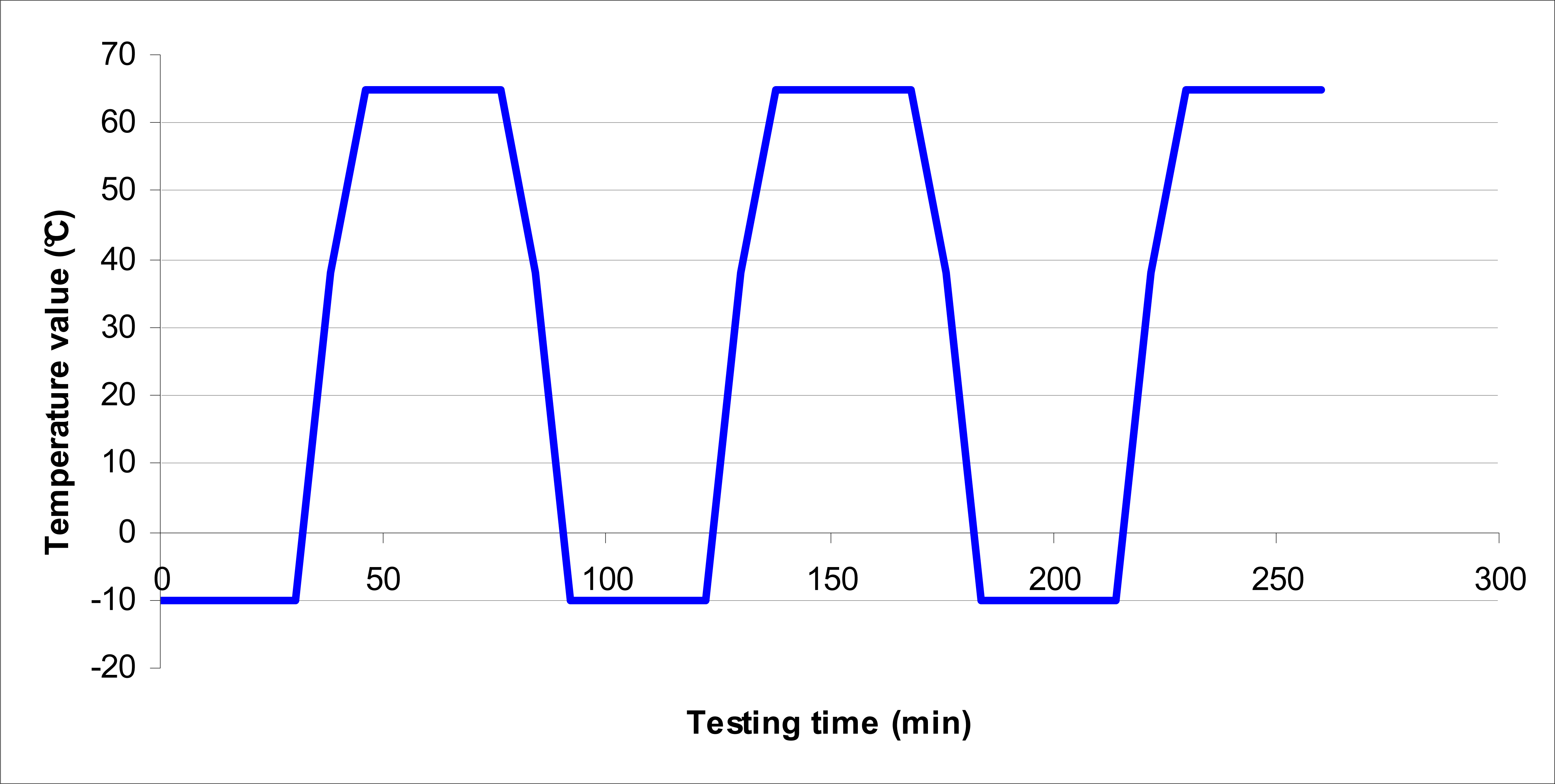
Figure 3.
Standard IEC-68-2-38 for temperature.

Figure 4.
Standard IEC-68-2-38 for humidity

Figure 5.
Example of program for Burn-in test.

Figure 6.
Brief presentation of essential data transfer and task sequence of Remote Control System based on standard BPMN (Business Process Modeling Notation) symbols [12].
Figure 6.
Brief presentation of essential data transfer and task sequence of Remote Control System based on standard BPMN (Business Process Modeling Notation) symbols [12].

Figure 7.
Automatic selection.

Figure 8.
Selecting standard.

Figure 9.
Inserting parameter limits.

Figure 10.
Results of providing environment in the chamber as to standard IEC-68-2-38.

© 2007 by MDPI ( http://www.mdpi.org). Reproduction is permitted for noncommercial purposes.
Share and Cite
MDPI and ACS Style
Brezovec, B.; Matko, V. Software and Equipment for Remote Testing of Sensors. Sensors 2007, 7, 1306-1316. https://doi.org/10.3390/s7071306
AMA Style
Brezovec B, Matko V. Software and Equipment for Remote Testing of Sensors. Sensors. 2007; 7(7):1306-1316. https://doi.org/10.3390/s7071306
Chicago/Turabian StyleBrezovec, Barbara, and Vojko Matko. 2007. "Software and Equipment for Remote Testing of Sensors" Sensors 7, no. 7: 1306-1316. https://doi.org/10.3390/s7071306