Study of the origin of bending induced by bimetallic effect on microcantilever

BioNanoMechanics Lab, National Centre for Microelectronics, IMM-CNM, CSIC Isaac Newton 8 (PTM), Tres Cantos 28760, Madrid, Spain
*
Author to whom correspondence should be addressed.
Sensors 2007, 7(9), 1757-1765; https://doi.org/10.3390/s7091757
Submission received: 30 July 2007
/
Accepted: 4 September 2007
/
Published: 5 September 2007
(This article belongs to the Special Issue Cantilever, Microcantilevers and Nanocantilever Sensors and Biosensors)
Abstract
:An analytical model for predicting the deflection and force of a bimaterial cantilever is presented. We introduce the clamping effect characterised by an axial load upon temperature changes. This new approach predicts a non linear thermal dependence of cantilever strain. A profilometry technique was used to measure the thermal strain. Comparison with experimental results is used to verify the model. The concordance of the analytical model presented with experimental measurements is better than 10%..
1. Introduction
Atomic force microscope (AFM) cantilevers are known to be very sensitive to temperature [1]. Bimaterial microcantilevers have been used for a large number of applications that take advantage of this thermal sensitivity, as well as the reduction in the size of the probe and the high parallelizability, that improve the sensitivity and spatial resolution of the measurements [2]. These applications have included spatially-resolved calorimetry [3-7], ferromagnetic resonance [8], thermomechanical data storage [9-10], nanolithography [11-14] and thermal actuators [15-17].
It has been shown that silicon microcantilevers with a thin gold film on one side undergo measurable bending in response to temperature changes. This phenomenon is frequently referred to as the “bimetallic effect”. In that particular case, the differential stress in the cantilever is created due to dissimilar thermal expansion coefficients of the silicon substrate and the gold coating. It has been estimated that the smallest heat change that can be detected using bimaterial microcantilevers lies in the femtojoule range [18].
Although previous publications [19, 20] in the field of micromechanics have described bimetallic cantilever microactuators, the derivation of the strain induced by temperature change for a cantilever clamped at one end is still incomplete. Furthermore, the origin of the force generated by such microactuators has been rarely discussed. In this communication, an analytical expression for the tip deflection and force of a bimetallic cantilever as a function of change in temperature is derived.
It will be demonstrated that the temperature dependent interfacial tension between gold and silicon layers leads to a non linear expression for the dependence of bending of the cantilever with temperature.
2. Theory
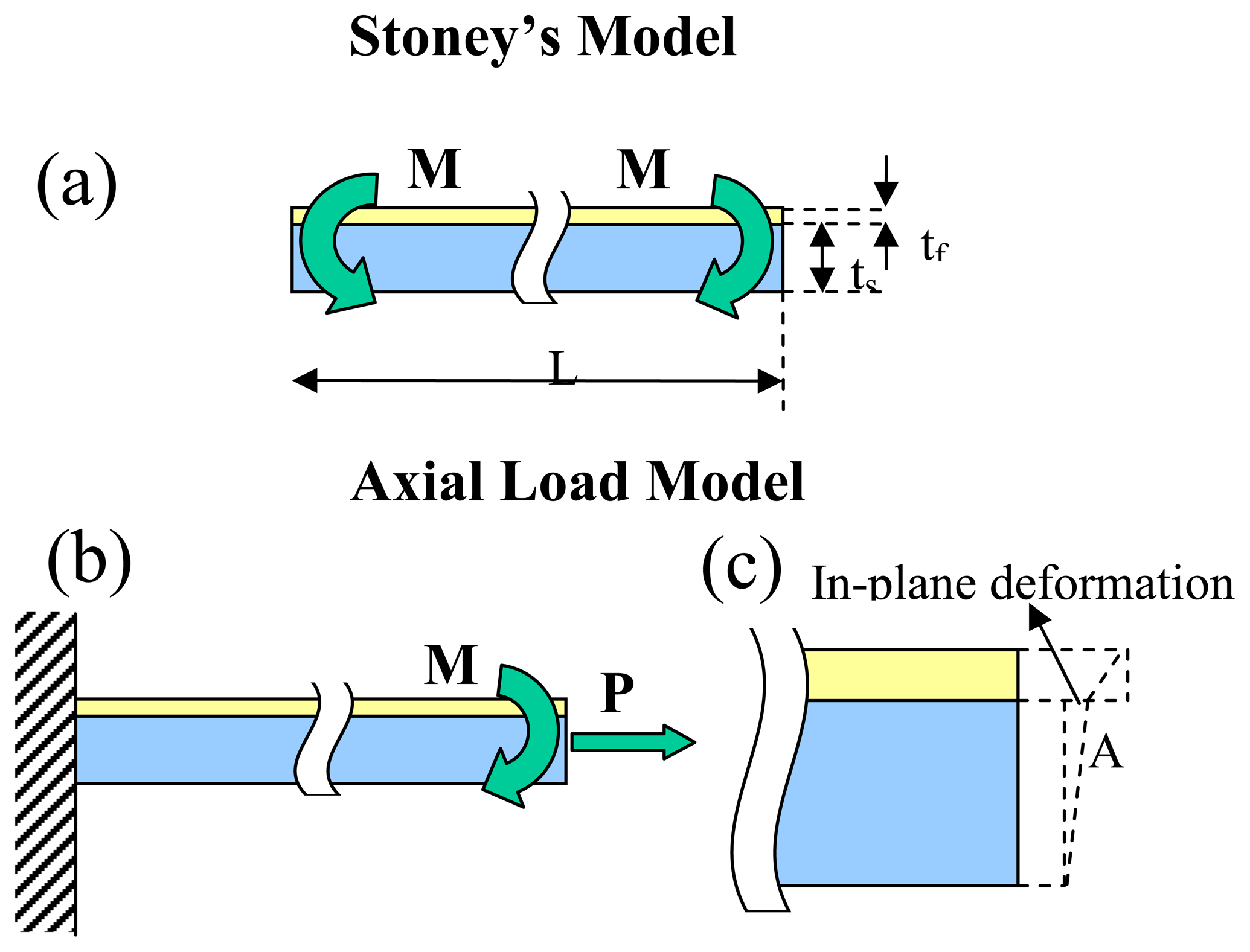
The Stoney's model describes the differential surface stress as a concentrated moment applied at the free end of the cantilever, Fig. 1a. Therefore, the governing equation of the beam deflection can be written as [21,22]
where x is the is the spatial coordinate along the cantilever length, v(x) the vertical displacement, E is the Young's modulus, I the moment of inertia and M the applied moment. Taking into account the boundary conditions the solution of the above equation is a parabolic profile
For a rectangular beam, the moment of inertia is
and the applied moment
, where w and t are respectively the width and the thickness of the beam and σ the differential surface stress between the upper and lower sides. Therefore, for a prismatic cantilever the deflection curve is
For a bilayer system, the Young modulus must be substituted by an effective value taking into account the thickness and the Young modulus of the both layers in the following way [24]
where the subscripts f and s refer respectively the film and the substrate. For the case of tf≪ts, the surface stress originated by the temperature change can be approximated as [25]
where αi are the thermal expansion coefficients of the film and the substrate and ΔT is the external variation of temperature. Usually, the surface stress is deduced by measuring the tip displacement of the cantilever. Substituting eq. (5) in the deflection curve and fixing the free end at the coordinate x we obtain a linear dependence with the temperature
where t=ts+tf is the total thickness. In this case the temperature dependence of the Young modulus of the cantilever materials has been neglected for the temperature variations commonly applied.
However, recent studies [25,26] have shown the necessity of including an axial load to complete the description of the dynamics of the cantilever deflection. This approach, depicted in Fig. 1b, leads to considering a different loading scenario and deformation system.
As it was discussed above, when the temperature changes, the difference in the thermal expansion coefficients and the Young's moduli of the cantilever materials leads to different linear deformations between the layers. Since the two materials are bonded, the interfacial line must reach some intermediate position, point A in Fig. 1c, causing an in-plane deformation. The physical origin of this deformation can be attributed to an axial load, P. Hence, the strain governing Equation (1) must be changed to
where the axial load depends on the system geometry. P = wσ. Eq. 7 can be analytically solved,
and at the cantilever free end the deflection can be written as
In this new loading scenario the temperature dependence of the deflection of the free end of the cantilever is not linear.
3. Experimental Section
We have used commercially available silicon cantilevers in our experiments (MikroMash). These cantilevers are rectangular; their nominal dimensions are 400 μm in length, 100 μm in width, and 1 μm in thickness. Thermal evaporation at a pressure of 10-5 Pa (0.2 nm/s) was then used to deposit a 2-nm-thick film of chromium and a 20 nm thick film of gold.
A cantilever holding cell was developed in which a medium vacuum can be reached in about 10 min by using a turbomolecular pump. Control valves are used to maintain a given gas pressure. A heating Peltier resistor mounted on the cell's outside wall can heat or cool the whole cell in a –223 K/373 K range. The temperature within the cell can be controlled within 0.1% accuracy by using a model 325 Temperature Controller (Newport™). This T-control device ensures both thermistor operation by delivering output power of 17.5 W for the Peltier resistor and an ultra-stable temperature control (±0.001°C) over a broad temperature range.
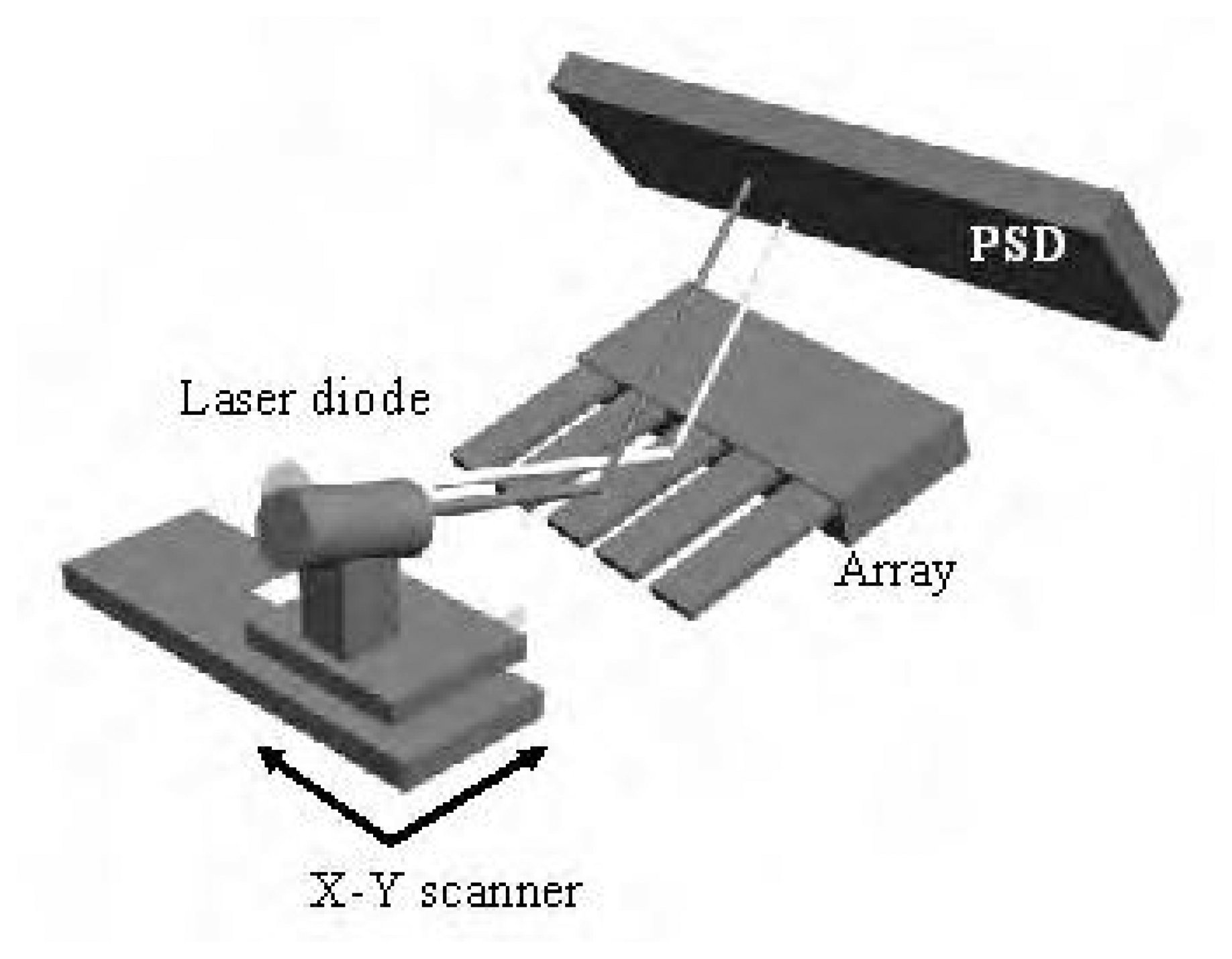
Cantilever bending is measured by home made scanning profilometry technique [27]. The readout technique combines the optical beam deflection method and the automated two-dimensional scanning of a single laser beam by means of voice-coil actuators. Fig. 2 shows a schematic drawing of the experimental device. A 3 mW laser diode is mounted onto a linear voice coil actuator that allow a nonhysteretic displacement over a range of several millimeters at speeds of up to 50 mm/s with an accuracy of 100 nm. The laser beam is directed to illuminate the cantilever and a two-dimensional linear position detector (PSD) is arranged to collect the reflected beams. A convergent lens is used to reduce the spot size of the laser on the cantilevers to 5–10 μm, approximately. The scanning is oriented parallel to the cantilever longitudinal axis in order to measure the cantilever profiles.
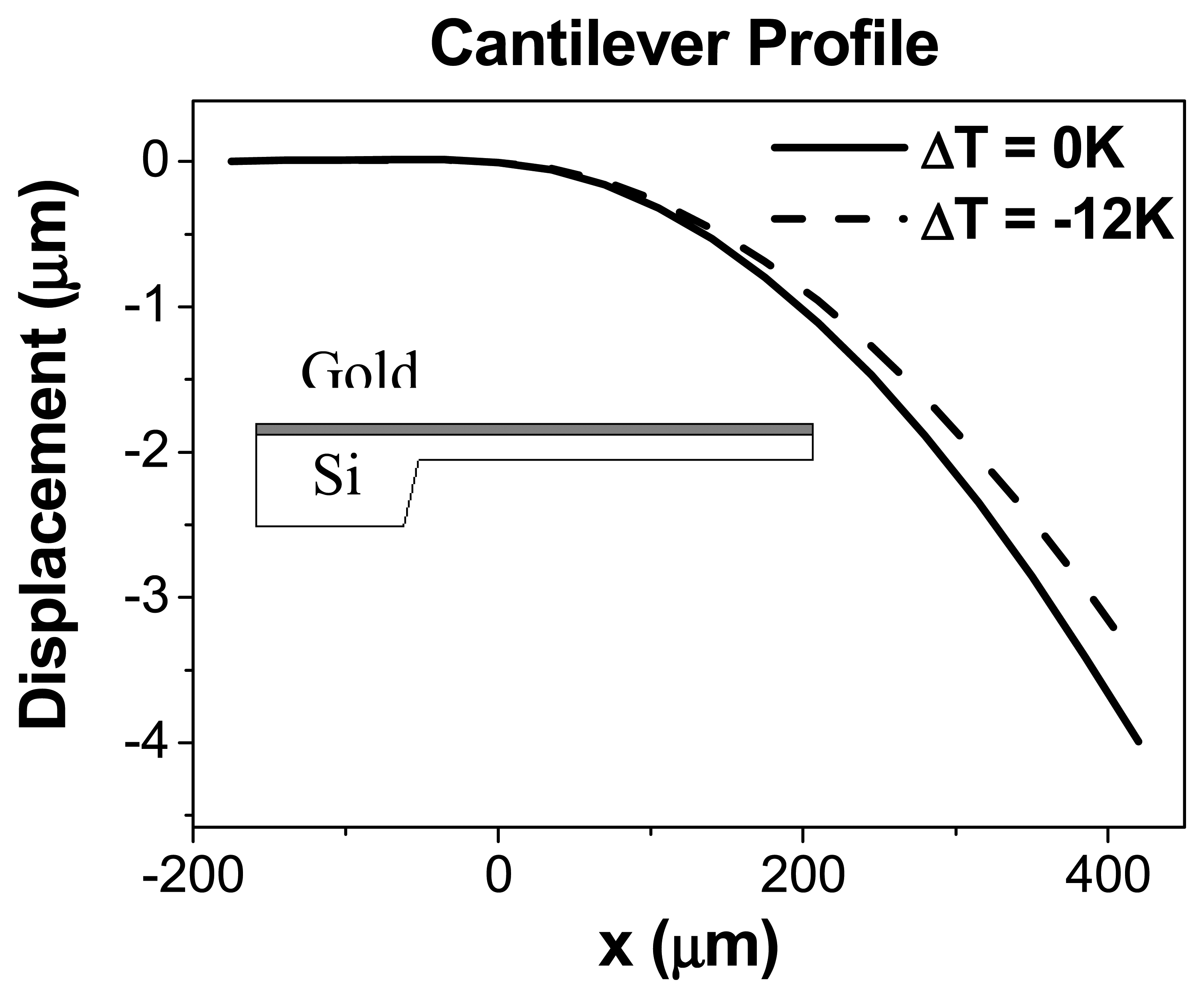
Fig. 3 shows the resulting cantilever profiles measured at P=10-2 Pa for two temperature variations ΔT= 0 K and ΔT=-12 K. According to our T-control device, ΔT=0 K corresponds to a temperature of 298 K. The scan speed was set to 1 mm/s and the longitudinal axis of the cantilever was selected with a precision of 100 nm. The cantilever free ends were determined at the positions where the total light intensity collected by the PSD falls to the half. When increasing temperature, the cantilevers displace downward, towards the silicon side. The displacement arises from the compressive surface stress on the gold due to the differential expansion of gold and silicon layers.
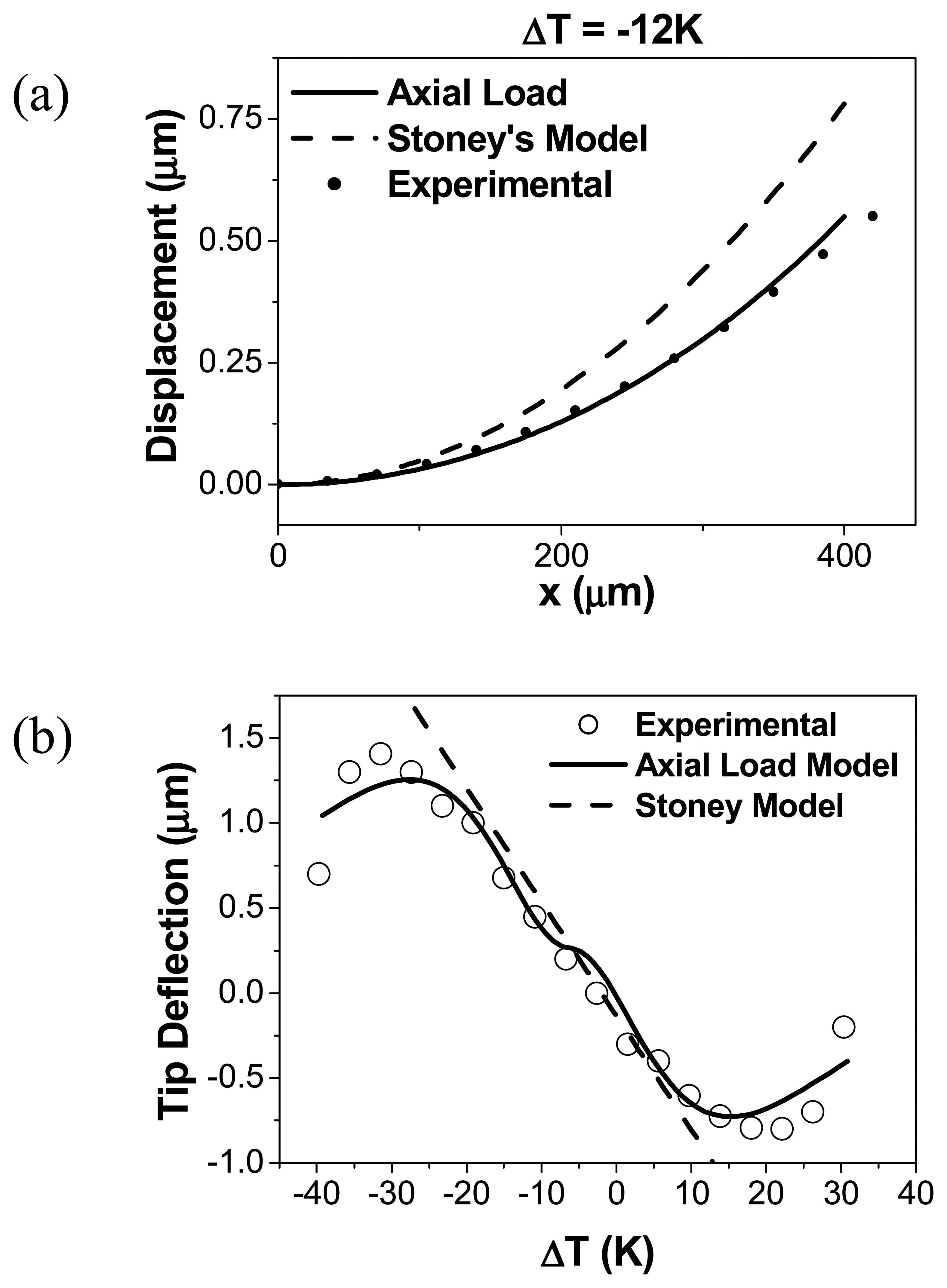
The data obtained from this profilometry technique permit observing the cantilever shape and measuring the exact deformation induced by ΔT. The end point deflection of the cantilever can also be measured. To elucidate the strain mechanisms of the cantilevers during temperature change, the initial cantilever profile (ΔT=0 K) was subtracted from the profiles at ΔT=-12 K. A maximum displacement of 53 nm is found at the free end of the cantilever. The measured deformation induce by the bimetallic effect was compared with the cantilever profile derived from the above models, as shown in Fig. 4a. As can be seen in this figure, for the same change of temperature, the Stoney's model predicts a cantilever displacement larger than the axial load model. This difference is a consequence of the flatten effect of the axial load. Therefore, for the same tip displacement, the surface stress derived from the Stoney's model is always smaller. The axial load model predict also a profile different in shape, as the force induced by the strain lead to a linear deformation component that differ from complete parabolic behavior expected from Stoney's model.
Fig. 4b shows the end tip deflection δ measured as a function of temperature change ΔT at P=10-2 Pa. The temperature T was gradually varied over a range between 235 K and 315 K. The bimetallic effect shows two different response regions as a function of ΔT:
In the first region between ΔT<-30K and ΔT>25K, the tip deflection increases with ΔT, whereas it should decrease if we refer to the Stoney's model for a cantilever consisting of two layers with two different coefficients of thermal expansion. This behavior illustrates the difference between this classical model and the axial load model which fits well with the experimental data for ΔT> 25K.
In the second region; for ΔT>-30K and ΔT<25K, δ decreases following a linear dependence with ΔT of 43 nm/K. The Stoney's model predict a larger slope of -67 nm/K. Hence, the Stoney's model prediction is also not accurate for small ΔT.
The in-plane strain of the interface at the interface of gold and silicon layer film may explain the nonlinearity in the stress variation with ΔT. The independent thermal strains of the two cantilever layers induce an axial force. The cantilever stops bending when the applied stress induced by the thermal change exceeds axial force coefficient. This force can be considered as bulk effects because the temperature change affects the whole of the thickness. This is the main difference compared with the adsorption induced strain, where the generated stress is confined to the surface.
Conclusions
In this work the origin of the bending caused by bimetallic effect has been studied. The bimetallic effect is theoretically modelled taking into account the forces involved in the thermal expansion of the two layers. As was shown in the theory, this load is responsible of a non-linear dependence of the tip deflection of the cantilever with the temperature variation. This theoretical conclusion was experimentally validated. The result of this work can be generalized to other geometries to improve the temperature control of bimaterial cantilever based device.
Acknowledgments
The authors acknowledge financial support from Ministerio de Educación y Ciencia (TEC2006-10316/MIC), CSIC and Comunidad de Madrid (200550M056). D. Ramos acknowledges the Comunidad de Madrid fellowship.
References and Notes
- Mertens, J.; Finot, E.; Thundat, T.; Fabre, A.; Nadal, M.-H.; Eyraud, V.; Bourillot, E. Effects of temperature and pressure on microcantilever resonance response. Ultramicroscopy 2003, 97, 119. [Google Scholar]
- King, W.P.; Saxena, S.; Nelson, B.A. Nanoscale thermal analysis of an energetic material. Nano Letters 2006, 6, 2145. [Google Scholar]
- Nonnenmacher, M.; Wickramasinghe, H. K. Scanning probe microscopy of thermal conductivity and subsurface properties. Applied Physics Letters 1992, 61, 168. [Google Scholar]
- Abedinov, N.; Grabiec, P.; Gotszalk, T.; Ivanov, Tz.; Voigt, J.; Rangelow, I.W. Micromachined piezoresistive cantilever array with integrated resistive microheater for calorimetry and mass detection. Journal of Vacuum Science and Technology A 2001, 19, 2884. [Google Scholar]
- Gotsmann, B.; Durig, U. Thermally activated nanowear modes of a polymer surface induced by a heated tip. Langmuir 2004, 20, 1495. [Google Scholar]
- Berger, R.; Lang, H.; Gerber, C.; Gimzewski, J.; Fabian, J.; Scandella, L.; Meyer, E.; Guntherodt, H. Micromechanical thermogravimetry. Chemical Physics Letter 1998, 294, 363. [Google Scholar]
- Pinnaduwage, L.A.; Wig, A.; Hedden, D.L.; Gehl, A.; Yi, D.; Thundat, T.; Lareau, R.T. Detection of trinitrotoluene via deflagration on a microcantilever. Journal of Applied Physics 2004, 95, 5871. [Google Scholar]
- Wallis, T.M.; Moreland, J.; Riddle, B.; Kabos, P. Microwave power imaging with ferromagnetic calorimeter probes on bimaterial cantilevers. Journal of Magnetism and Magnetic Material 2005, 286, 320. [Google Scholar]
- King, W.P.; Kenny, T.W.; Goodson, K.E.; G. Cross, G.; Despont, M.; Durig, U.; H. Rothuizen, H.; Binnig, G.K.; Vettiger, P. Atomic force microscope cantilevers for combined thermomechanical data writing and reading. Applied Physics Letters 2001, 78, 1300. [Google Scholar]
- Mamin, H. J.; Fan, L.S.; Rugar, D.; Hoen, S. Tip-based data storage using micromechanical cantilevers. Sensors and Actuators A: Physical 1995, 48, 215–219. [Google Scholar]
- Wang, D. A.; Bullen, J.; Zou, C.; Liu, J.; Mirkin, C. Thermally actuated probe array for parallel dip-pen nanolithography. Journal of Vacuum Science and Technology B 2004, 22, 2563. [Google Scholar]
- Gotsmann, B.; Duerig, U.; Frommer, J.; Hawker, C. J. Exploiting chemical switching in a Diels-Alder polymer for nanoscale probe lithography and data storage. Advanced Functional Materials 2006, 16, 1499. [Google Scholar]
- Sheehan, P. E.; Whitman, L.J.; King, W.P.; Nelson, B. A. Nanoscale deposition of solid inks via thermal dip pen nanolithography. Applied Physics Letter 2004, 85, 1589. [Google Scholar]
- Nishimura, S.; Takemura, Y.; Shirakashi, J. SPM local oxidation nanolithography with active control of cantilever dynamics. Journal of Physics: Conference Series 2007, 61, 1066. [Google Scholar]
- Lalinský, T.; Burian, E.; Drzृk, M.; Hascृk, S.; Mozolová, Z.; Kuzmृk, J. Thermal actuation of a GaAs cantilever beam. Journal of Micromechanics and Microengineering 2000, 10, 293. [Google Scholar]
- Grigorov, A.V.; Davis, Z.J.; Rasmussen, P.; Boisen, A. A longitudinal thermal actuation principle for mass detection using a resonant micro-cantilever in a fluid medium. Microelectronic Engineering 2004, 73, 881. [Google Scholar]
- Sulchek, T.; Minne, S. C.; Adams, J.D.; Fletcher, D. A.; Atalar, A.; Quate, C.F.; Adderton, D.M. Dual integrated actuators for extended range high speed atomic force microscopy. Applied Physics Letters 1999, 75, 1637. [Google Scholar]
- Barnes, J.R.; Stephenson, R.J.; Welland, M.E.; Gerber, C.; Gimzewski, J.K. Photothermal spectroscopy with femtojoule sensitivity using a micromechanical device. Nature 1994, 372, 79. [Google Scholar]
- Chu, W.-H.; Mehregany, M.; Mullen, R. L. Analysis of tip deflection and cantilever force of a bimetallic cantilever microactuator. J. Micromech. Microeng. 1993, 3, 4–7. [Google Scholar]
- Shuir, E. Stresses in bi-metal thermostats. J. Appl. Mech. 1986, 53, 657–660. [Google Scholar]
- Stoney, G. G. The Tension of metallic films deposited by electrolysis. Proc. R. Soc. London, Ser. A 1909, 82, 172–175. [Google Scholar]
- Timoshenko, S. Analysis of bi-metal thermostats. J. Opt. Soc. Am. 1925, 11, 233–255. [Google Scholar]
- Yi, J. W.; Shih, W. Y.; Shih, W.-H. Effect of length, width, and mode on the mass detection sensitivity of piezoelectric unimorph cantilevers. J. Appl. Phys. 2002, 91, 1680–1686. [Google Scholar]
- Hsueh, C. H. Modeling of elastic deformation of multilayers due to residual stresses and external bending. J. Appl. Phys. 2002, 91, 9652–9656. [Google Scholar]
- MacFarland, A. W.; Poggi, M. A.; Doyle, M. J.; Bottomley, L. A.; Colton, J. S. Influence of surface stress on the resonance behavior of microcantilevers. Appl. Phys. Letts. 2005, 87, 053505. [Google Scholar]
- Zhang, Y.; Zhao, Y.-P. Applicability range of Stoney's formula and modified formulas for a film/substrate bilayer. J. Appl. Phys. 2006, 99, 053513. [Google Scholar]
- Mertens, J.; Álvarez, M.; Tamayo, J. Real-time profile of microcantilevers for sensing applications. Appl. Phys. Lett. 2005, 87, 2344102. [Google Scholar]
Figure 1.
Scheme of (a) the Stoney's model for a plate deformation. The strain is derived from a moment applied at the free end of the cantilever. (b) the axial load model. An axial load component is added to take in account the effect of the clamping and also (c) the force induced by the displacement of the layer at the interface.

Figure 2.
Sketch of the profilometry system. The laser is mounted in a 2-D voice-coil actuator. The beam can scan the cantilever array in the X and Y directions. The beam reflected of the cantilever surface is collected in a position sensitive diode.
Figure 2.
Sketch of the profilometry system. The laser is mounted in a 2-D voice-coil actuator. The beam can scan the cantilever array in the X and Y directions. The beam reflected of the cantilever surface is collected in a position sensitive diode.

Figure 3.
The cantilever profiles for ΔT= 0K and ΔT=-12K are presented. The cantilever bends upwards when the temperature decreases. A schematic depiction of the cantilever is also shown to relate the sign of the cantilever bending to the orientation of the bimetallic cantilever. The profiles were obtained in medium vacuum (10-2Pa).

Fig. 4.
(a) Cantilever deformation predicted from the Stoney's model (dashed line) and the axial load model (solid line) for ΔT=-12 K. The two profiles are different in shape, as the axial load model does not show a complete parabolic behavior when temperature change. The experimental deflection profile fits with the axial load profile within a 10 % accuracy. (b) End tip deflection measured as function of ΔT. Theoretical value calculated from the Stoney's model (dashed line) and the axial load model (solid line) are added for comparison. The parameters used in this fitting are: Es = 169 GPa, Ef = 79 Gpa, αs = 2.59 10-6 K-1, αf = 14.2 10-6 K-1. The profiles were obtained in medium vacuum (10-2 Pa).

© 2007 by MDPI ( http://www.mdpi.org). Reproduction is permitted for noncommercial purposes.
Share and Cite
MDPI and ACS Style
Ramos, D.; Mertens, J.; Calleja, M.; Tamayo, J. Study of the origin of bending induced by bimetallic effect on microcantilever. Sensors 2007, 7, 1757-1765. https://doi.org/10.3390/s7091757
AMA Style
Ramos D, Mertens J, Calleja M, Tamayo J. Study of the origin of bending induced by bimetallic effect on microcantilever. Sensors. 2007; 7(9):1757-1765. https://doi.org/10.3390/s7091757
Chicago/Turabian StyleRamos, Daniel, Johann Mertens, Montserrat Calleja, and Javier Tamayo. 2007. "Study of the origin of bending induced by bimetallic effect on microcantilever" Sensors 7, no. 9: 1757-1765. https://doi.org/10.3390/s7091757