Experimental Study on the Effects of Alumina Abrasive Particle Behavior in MR Polishing for MEMS Applications

1
Division of Mechanical Engineering, Inha University, Incheon 402-751, Korea
2
Department of Mechanical Engineering, University of Incheon, Incheon 402-751, Korea
3
Nano-Mechanical Systems Technology Division, KIMM, Daejeon 305-343, Korea
*
Author to whom correspondence should be addressed.
Sensors 2008, 8(1), 222-235; https://doi.org/10.3390/s8010222
Submission received: 30 November 2007
/
Accepted: 8 January 2008
/
Published: 21 January 2008
(This article belongs to the Special Issue Modeling, Testing and Reliability Issues in MEMS Engineering)
Abstract
:Recently, the magnetorheological (MR) polishing process has been examined as a new ultra-precision polishing technology for micro parts in MEMS applications. In the MR polishing process, the magnetic force plays a dominant role. This method uses MR fluids which contains micro abrasives as a polishing media. The objective of the present research is to shed light onto the material removal mechanism under various slurry conditions for polishing and to investigate surface characteristics, including shape analysis and surface roughness measurement, of spots obtained from the MR polishing process using alumina abrasives. A series of basic experiments were first performed to determine the optimum polishing conditions for BK7 glass using prepared slurries by changing the process parameters, such as wheel rotating speed and electric current. Using the obtained results, groove polishing was then performed and the results are investigated. Outstanding surface roughness of Ra=3.8nm was obtained on the BK7 glass specimen. The present results highlight the possibility of applying this polishing method to ultra-precision micro parts production, especially in MEMS applications.
1. Introduction
Recently, several new ultra-precision polishing technologies using smart materials such as electrorheological (ER) fluids [1] or magnetorheological (MR) fluids [2] have been focused upon for the production of micro parts in MEMS applications. These methods are considered potentially effective solutions to solve problems arising in traditional polishing methods, including pressure control, pad wear, subsurface damage, and micro crack propagation problems. In this study, variation of the machined surface characteristics of BK7 glass is investigated in a polishing process using MR fluids containing alumina micro abrasives and necessary stabilizers.
MR fluids are suspensions of very small magnetic additives, such as carbonyl iron (CI), and non-magnetic fluids such as mineral oils or water. MR fluids are known as controllable smart materials, since their flow properties, such as viscosity and stiffness, can be easily changed using externally imposed magnetic fields. Under imposed magnetic fields, MR fluids can be reversibly transformed from a fluid-like state to a solid-like state within milliseconds due to the formation of chain clusters of magnetic particles in the fluids.[3,4] These special characteristics of MR fluids can be applied to polishing processes of micro shapes or parts. MR fluids can produce high stress and pressure on the workpiece surface, based on Bingham lubrication theory and the Preston equation.[5] In the MR finishing process, the surface roughness and material removal rate (MRR) of the workpiece are affected by the process parameters, such as the properties of the employed nonmagnetic abrasives (particle material, size, aspect ratio, density, etc.), rotating wheel speed, imposed magnetic field density, machining depth, etc.
The objectives of the present research are to elucidate the material removal mechanism related to MR fluids for the polishing of BK7 glass, and to investigate the impact on surface roughness of the MR polishing process. Four kinds of alumina based slurries are produced for the experiments. A series of experiments are then performed to determine the appropriate process parameters. The material removal rate, surface profile, and roughness distributions are measured. From the results, it can be concluded that ultra-precision surface roughness of 3.8nm can be obtained under proper process parameters. The present results highlight the possibility of applying a polishing method using MR fluids to ultra-precision micro parts production, especially in MEMS applications.
2. Characteristics of MR Fluids
2.1. Polishing Principle Using MR Fluids
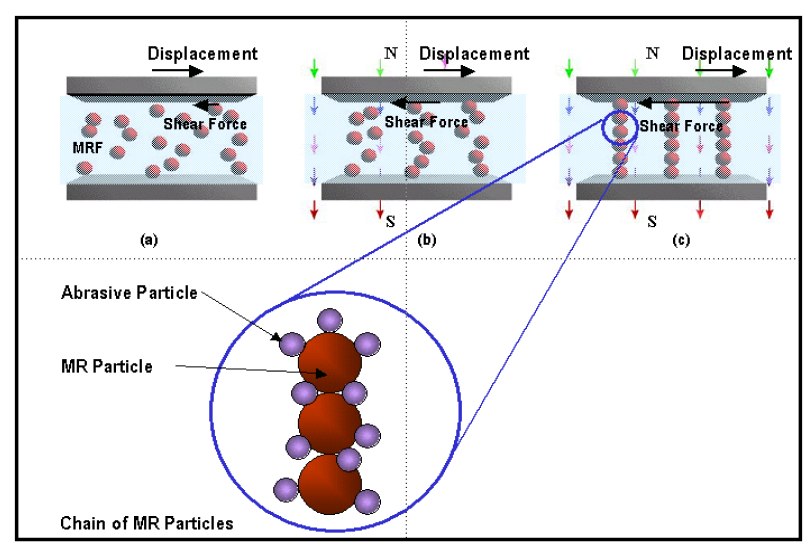
MR fluid is a phase-controllable suspension comprising a mixture of micro-size magnetic particles and non-magnetic fluids such as mineral oils or water. MR fluids are known smart materials, since their flow properties can be readily changed according to the imposed magnetic field intensity. Under an imposed magnetic field, the MR fluid can form chain-like structures via magnetization of the particles in the fluid, as shown in the Figure 1. This phenomenon is called the “MR effect”; and it can reversibly transform the fluid from a fluid-like state to a solid-like state within milliseconds.[6,7] The basic characteristic of this material is the ability to change rapidly from a Newtonian fluid to a strong semisolid substance under the applied magnetic field. As a result of this transformation, the flow properties of the fluid, such as viscosity and stiffness, increase according to the imposed magnetic field strength due to increased resistance to shear stress. Owing to these characteristics, MR fluids can be applied to dampers, clutches, and polishing systems.[6,7] To use a MR fluid as a polishing media, proper abrasives should be added to the fluid; these abrasives adhere to the MR particles, as shown in the Figure 1.
A schematic diagram of the MR polishing mechanism is shown in Figure 2. As shown here, the MR fluid is supplied to the gap between a workpiece and a moving wall (a vertically rotating wheel in this study). When the MR fluid is influenced by the applied magnetic field, the viscosity and stiffness of the fluid increase by more than several tens of times within milliseconds; the fluid then becomes a Bingham plastic fluid.[8] Thus, the MR fluid can rotate continuously as long as it adheres to the wheel surface by the applied magnetic field. For polishing purposes, an abrasive slurry (mixture of DI water and abrasive particles) is incorporated into the fluid, which is supplied to the narrow gap between the wheel and workpiece. At this point in the process, the abrasive particles (generally, nonmagnetic materials) are restricted to the upper part of the MR fluid, so that they can polish the surface of the workpiece. Here, the field of interest is the zone of the magnetic field, where polishing is to be carried out. Figure 3(a) shows an illustration of a cross-sectional view of this zone, and the box in Figure 3(b) denotes the polishing zone. Figure 4 shows the analyzed and measured magnetic field intensity along vertical and horizontal directions at the polishing zone shown in Figure 3(b). From the figures it can be seen that the central part between the pole pieces forms a strong magnetic field by the electromagnetic rolling up coil. Because the magnetic field of the wheel surface is much higher than that at the surface of the nonmagnetic workpiece, the magnetic particles are compressed on the surface of the wheel. Thus, the magnetic particles in the MR fluid push the abrasive particles to the surface of the workpiece, making the polishing process possible.
2.2. Flow Characteristics and Material Removal Rate in MR Polishing
The basic governing equation of the fluid lubrication adopted in this work can be expressed as follows: [8]
where, P is the contacting pressure and τxy is the shear stress. Integration of the above formula gives the following equation.
By substituting the imposed boundary conditions, the shear stress distribution can be obtained as
where h(x) is the distance between the wheel and workpiece, and U is the wheel speed. Preston's equation [3,4] can then be applied to obtain the material removal rate in using MR fluids as follows:
Thus, the material removal rate R can be controlled by changing the normal pressure P and the relative velocity U between the polishing wheel and the target workpiece.
3. Experimental Setup and Polishing Conditions
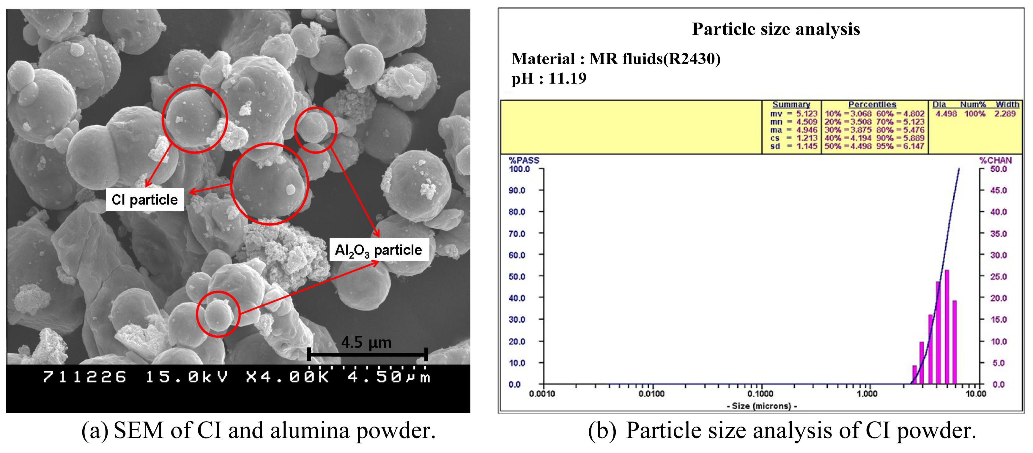
To prepare the required MR fluids for MR polishing, carbonyl iron powder, which is sensitive to magnetic fields, is used. The fluids consist of about 40 vol% magnetic particles, abrasive particles (alumina in this research), and DI-water. A dispersion stabilizer such as glycerol is added to the aforementioned materials as it enhances cohesion of the magnetic fluids and facilitates proper mixing of the polishing slurry and magnetic particles. Photographs of the MR polishing system for the experiments are shown in Figure 5. BK7 glass is used for the workpiece in the basic polishing experiments. The properties of BK7 are listed in Table 1. A SEM photograph and the particle size analysis results are shown in Figure 6. CI powder properties and composition properties of the MR fluid used for experiments are listed in Table 2 and 3, respectively. The experiment is comprised of two basic stages. First, four abrasive slurry conditions are established and compared, as shown in Table 4. Second, the characteristics of polishing spots and material removal rates under different conditions of wheel speed and changes of electric currents are evaluated. For all conditions, the gap between the wheel and workpiece is maintained at 0.8mm, and the slurry supply flow rate is set to 45 ml/sec. Polishing times are set to 20 seconds. Detailed conditions are provided in Table 5.
4. Experimental Results and Analysis
4.1. Basic Experimental Results
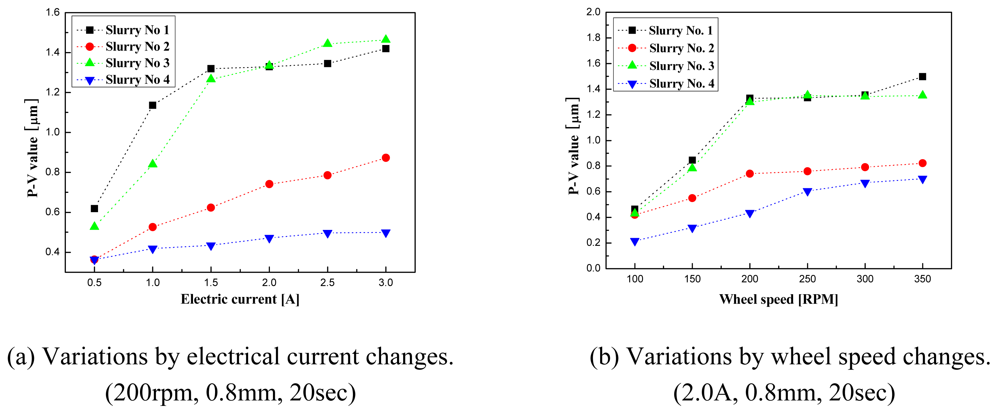
To determine the optimal polishing conditions using the prepared alumina slurries, the material removal rate and surface roughness of the polishing spots are measured by changing the electrical currents and the wheel rotating speeds. Figure 7 shows the summarized results of the variation of the removed depth according to current changes (a), and wheel speed changes (b). It can be seen that the removed depth increases with increased wheel speed and electrical current for all slurries. An increase of electrical current increases the strength of the magnetic field, which leads to an increase in the viscosity of the MR fluids. Thus, the removed depth is also increased, since higher viscosity can generate higher shear forces in the polishing processes. However, it is observed that the rate of increase of removed depth decelerates after a certain level of speed. It appears that an overly high rotational speed may lead to excessive yield stress, which destroys the chain structures among the particles. It could also cause slipping between the wheel surface and MR fluid.
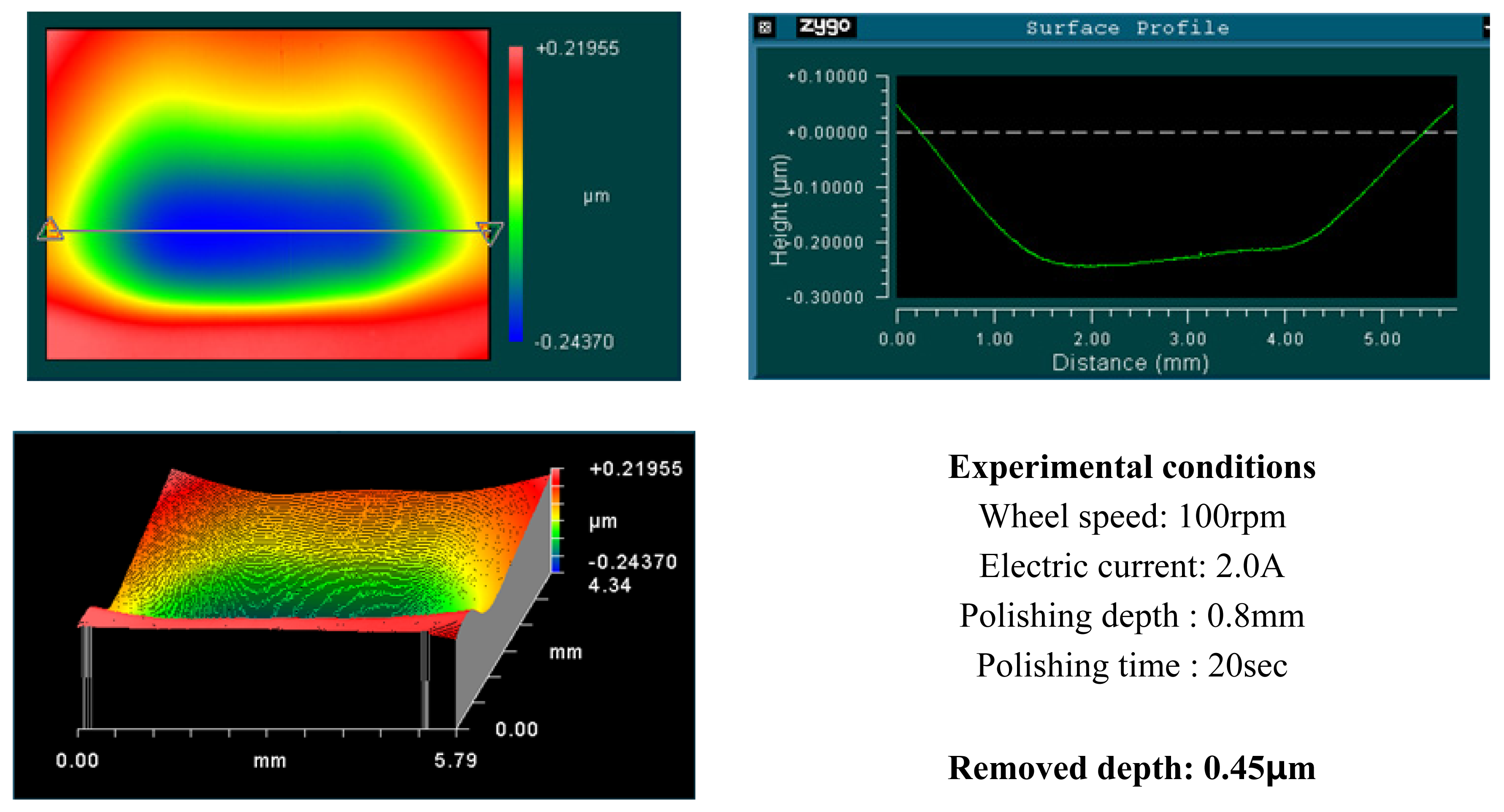
Figure 8, 9, 10, 11, 12, 13, 14 and 15 show the measured surface roughness and a profile of polishing spots using the prepared slurries No.1-4 under the imposed process conditions. As can be seen in Figure 12 and 13, slurry No. 3 gives more consistent and desirable results, including more desirable polishing spot profiles and better surface roughness compared to other slurry conditions.
4.2. Groove Polishing Using Slurry No.3
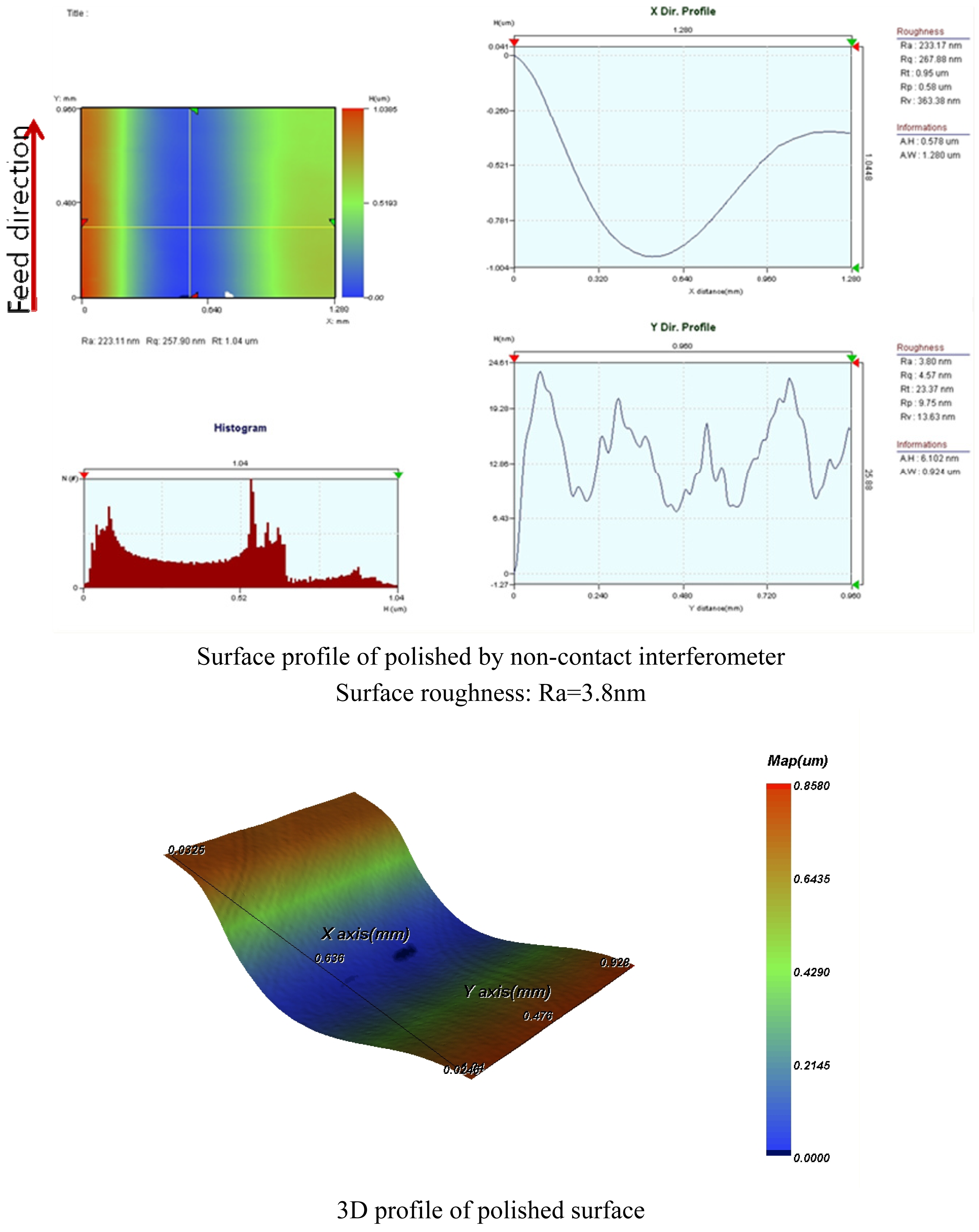
From the basic experiments, it can be seen that slurry condition No.3 provides the best polishing results among the prepared slurries. Groove polishing is therefore subsequently performed using these conditions. The experimental conditions are: wheel speed=100rpm, electric current=2A, and polishing depth=0.8mm. A surface roughness of Ra=3.8nm is consequently obtained for BK7 glass. The measured results of the surface profiles and roughness distributions of the workpiece after MR polishing are shown in Figure 16.
5. Conclusions
This study investigated an ultra-precision polishing methodology using MR fluids. Four slurries based on alumina were mixed, and the polishing characteristics of the slurries were experimentally investigated by changing process parameters such as electric current and wheel speed. From the study, the following results were obtained.
- (1)
- Effects of alumina abrasive particle behavior for MR polishing on BK7 glass were experimentally studied.
- (2)
- Viscosity of the MR fluids increased with increased imposed magnetic fields and electric currents.
- (3)
- Material removal rate increases with increased wheel speed and electric current; however, the rate of increase decelerated when the values exceeded certain levels. This phenomenon is due to chain structure breakage between the MR particles, and slipping between the wheel and the MR fluids by excessive shear stress.
- (4)
- Alumina slurry No.3 showed the best results. Using the conditions prescribed for this slurry, groove polishing on BK7 glass was performed. Outstanding surface roughness of Ra=3.8nm was obtained.
- (5)
- From the experimental results, it can be seen that the MR polishing method can be applied to fabricate micro parts, especially in MEMS.
- (6)
- It will be possible to obtain more advanced results through appropriate combinations of MR particles, micro abrasives, and process parameters.
References
- Akagami, Y.; Ogasawara, Y.; Nisimura, S. Characterization of particle motion for polishing and texturing under AC field by using particle dispersion type ER fluid. Smart structures and materials 1998, 593–598. [Google Scholar]
- Kim, K.D. A Controllable Micro Damper Using Magneto-Rheological Fluids. Journal of the KSPE 2000, 17, 41–45. [Google Scholar]
- Kormann, C.; Laun, H.M.; Laun, H.J. MR Fluids with nano-magnetic particles. International Journal of Modern Physics B 1996, 10, 3167–3172. [Google Scholar]
- Laun, S.D.; Arrasmith, S.R.; Kozhinova, I.A.; Gregg, L.; Shorey, A.B.; Romanofsky, H.J.; Golini, D. Studies of Material Removal in MRF from Polishing Spots. Ceramic Transactions 2000, 102, 201–212. [Google Scholar]
- Kordonski, W.I.; Jacobs, S.D. Magnetorheological Finishing. International Journal of Modern Physics B 1996, 10, 2837–2848. [Google Scholar]
- Golini, D.; Kordonski, W.I.; Dumas, P. Magnetorheological finishing(MRF) in commercial precision Optics Manufacturing. Optical Manufacturing and Testing 1999, 3782, 80–91. [Google Scholar]
- Kordonski, W.I.; Golini, D. Magnetorheological suspension–based finishing technology. Proceedings of SPIE-the international society for optical engineering 1998, 3326, 527–535. [Google Scholar]
- Kordonski, W.I.; Golini, D. Progress update in magnetorheological finishing. International Journal of Modern Physics B 1999, 13, 2205–2212. [Google Scholar]
Figure 1.
Chain cluster formation of MR particles.

Figure 2.
Imposed magnetic field and shear direction in MR polishing.
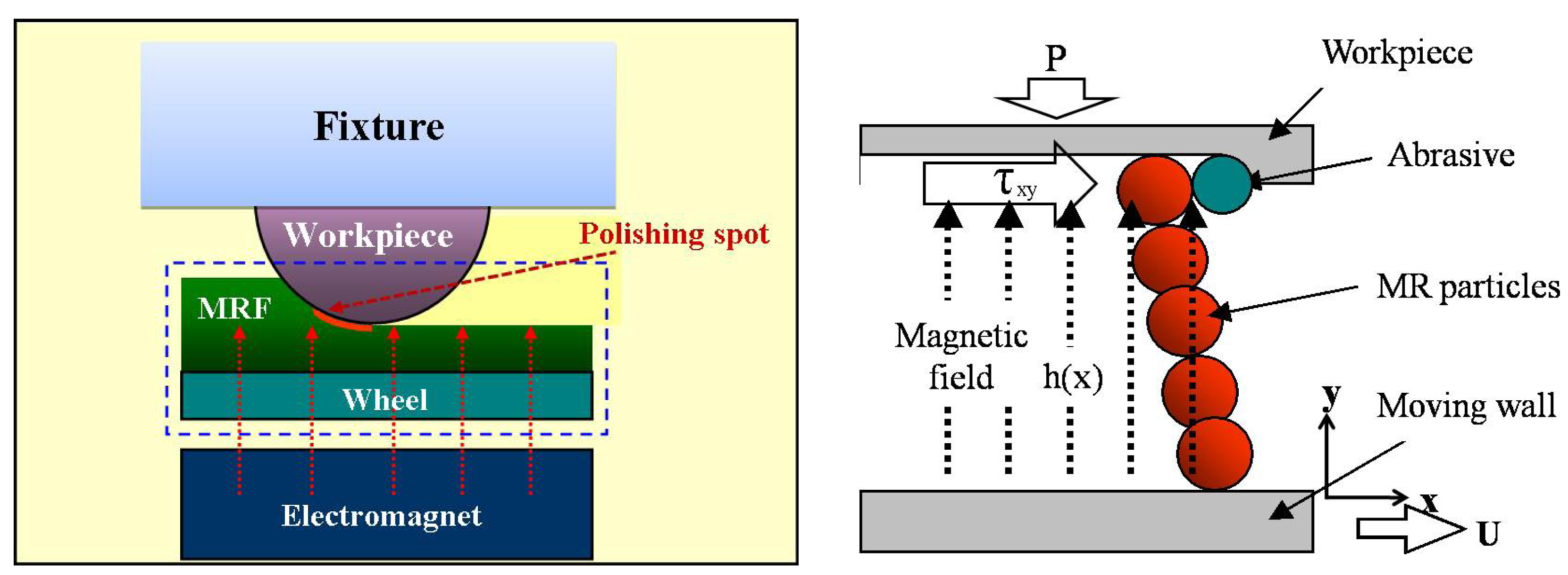
Figure 3.
Cross-sectional view of MR polishing zone.
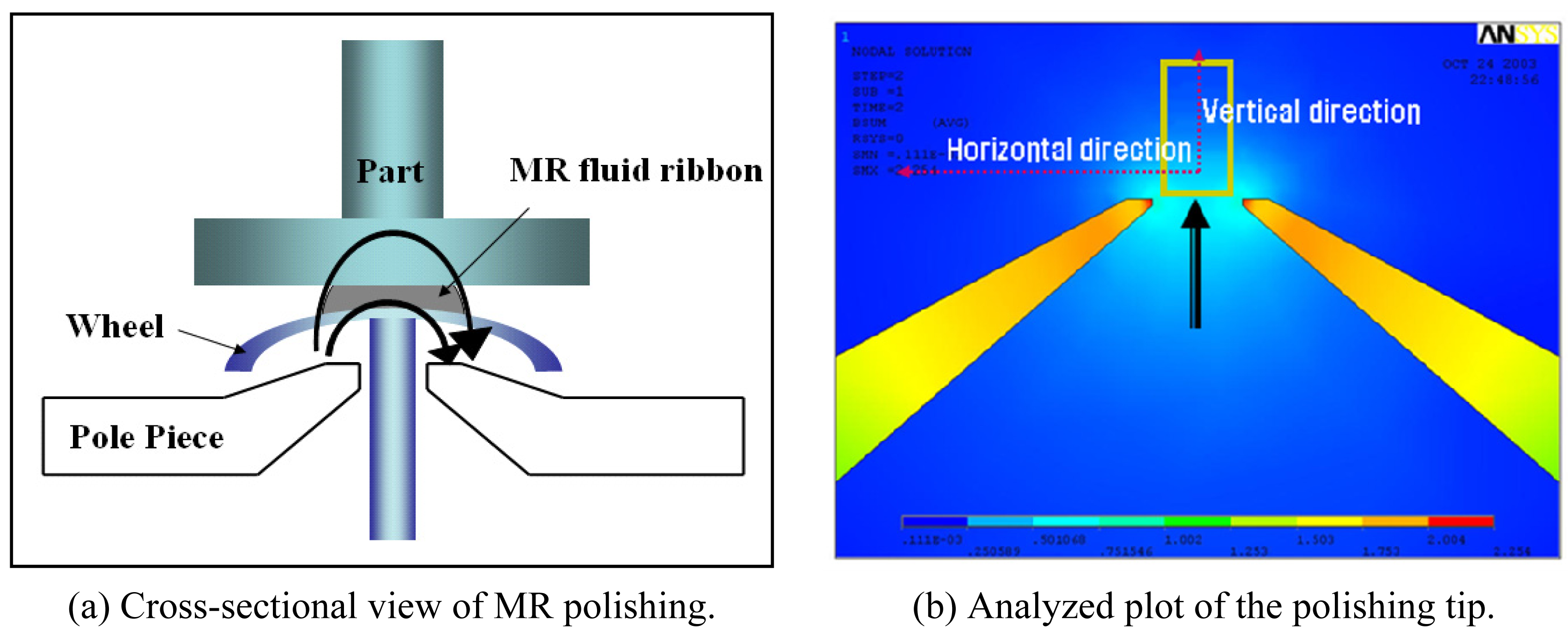
Figure 4.
Magnetic field distributions in the polishing zone.
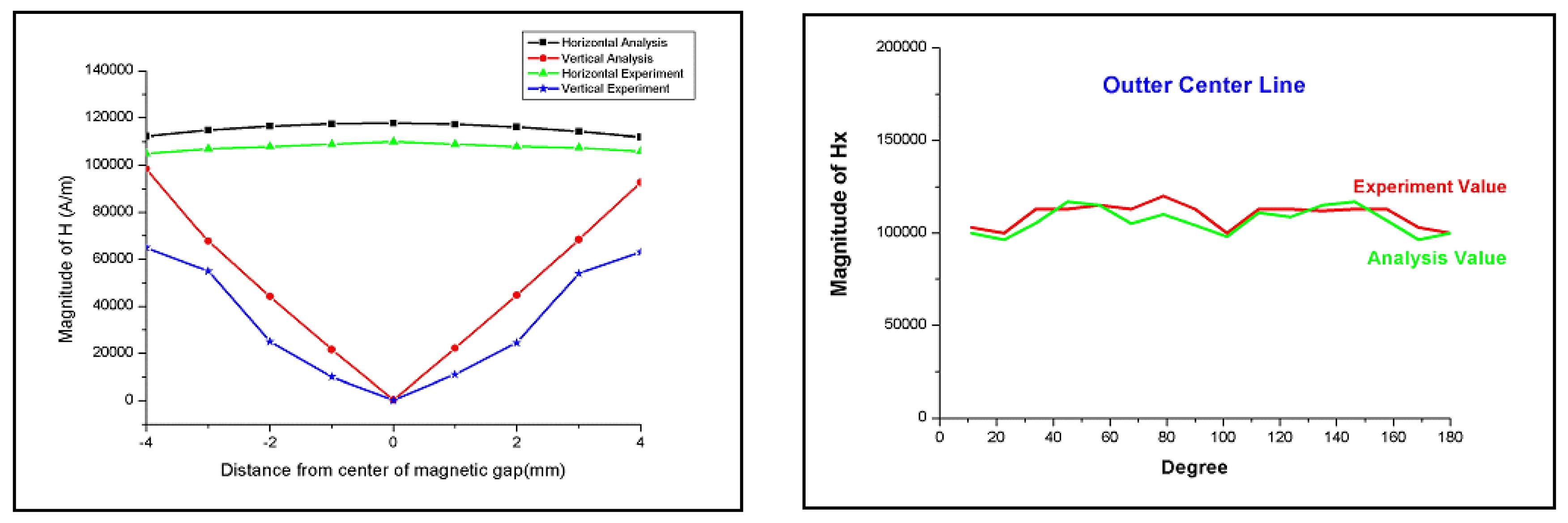
Figure 5.
Experimental setup for MR polishing.
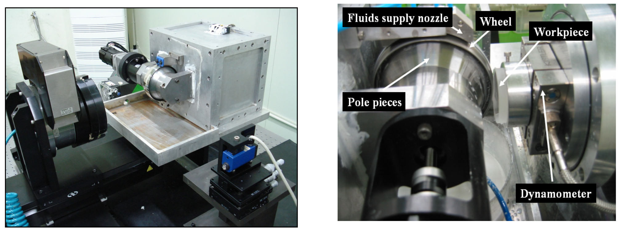
Figure 6.
Analysis of CI particle and alumina powder in MR fluid.

Figure 7.
Removed depth variations according to process parameter changes.

Figure 8.
Measured results after MR polishing using alumina slurry No.1 (100rpm and 2.0A)

Figure 9.
Measured results after MR polishing using alumina slurry No.1 (100rpm and 0.5A)
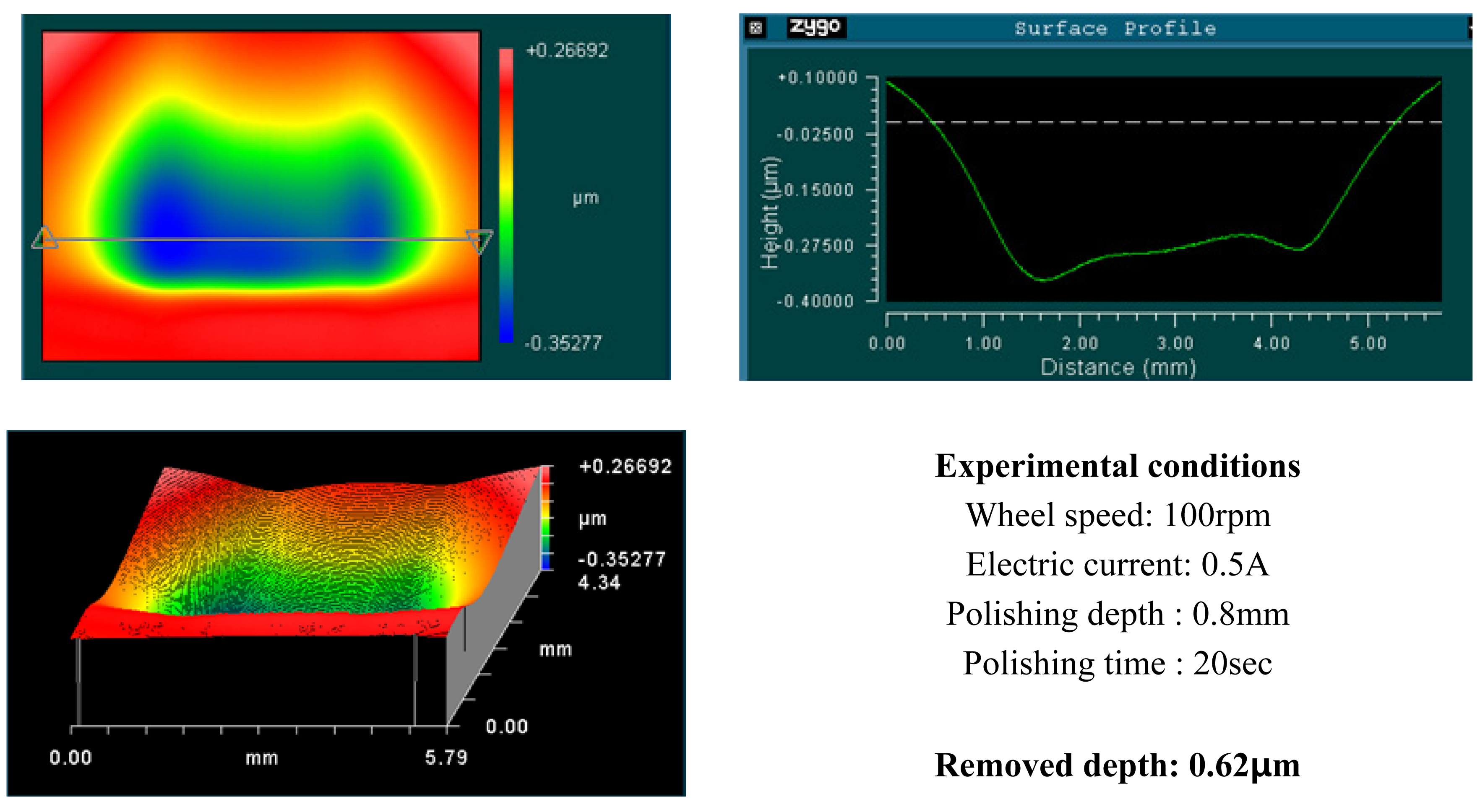
Figure 10.
Measured results after MR polishing using alumina slurry No.2 (100rpm and 2.0A).
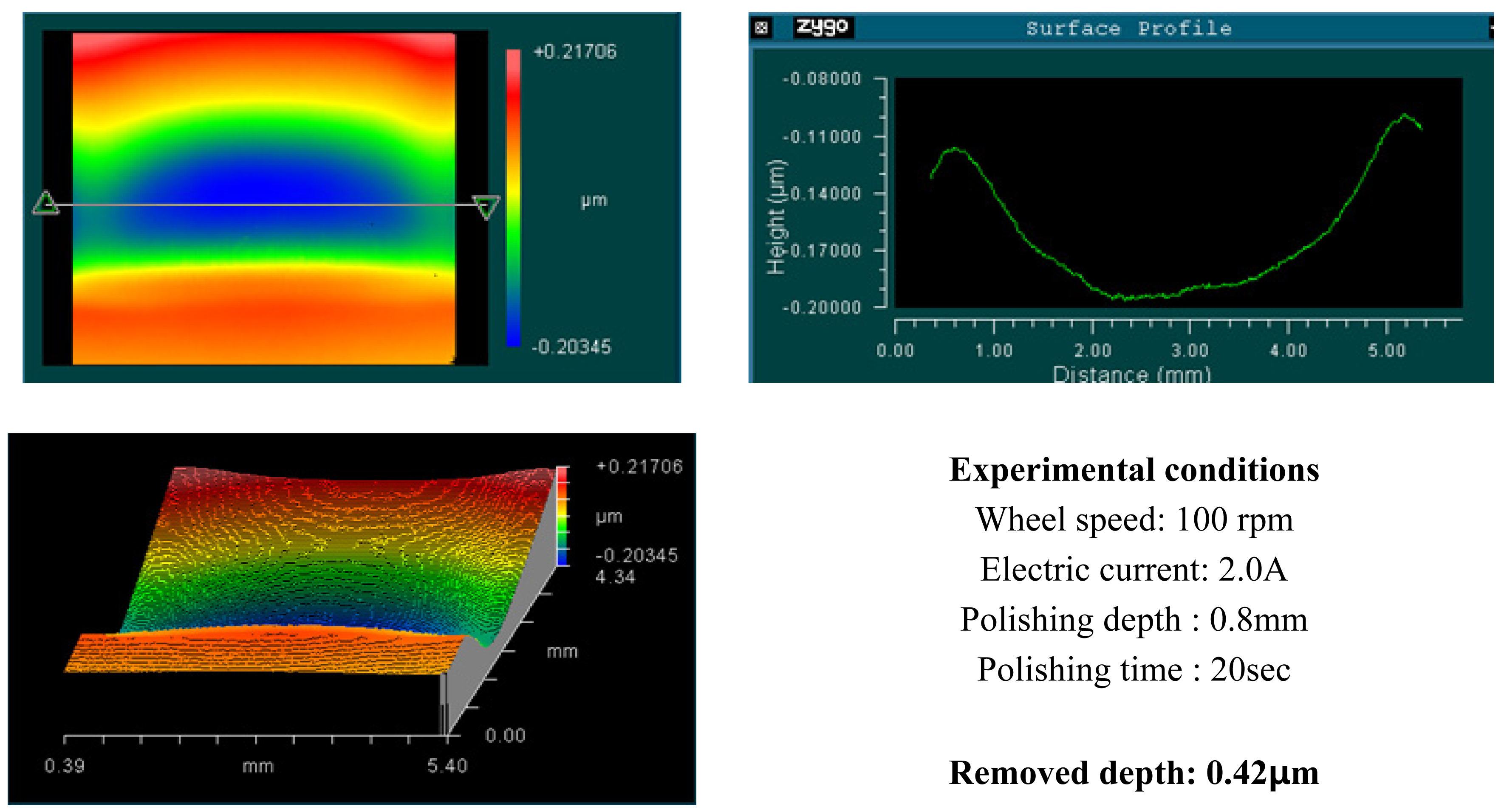
Figure 11.
Measured results after MR polishing using alumina slurry No.2 (100rpm and 0.5A).
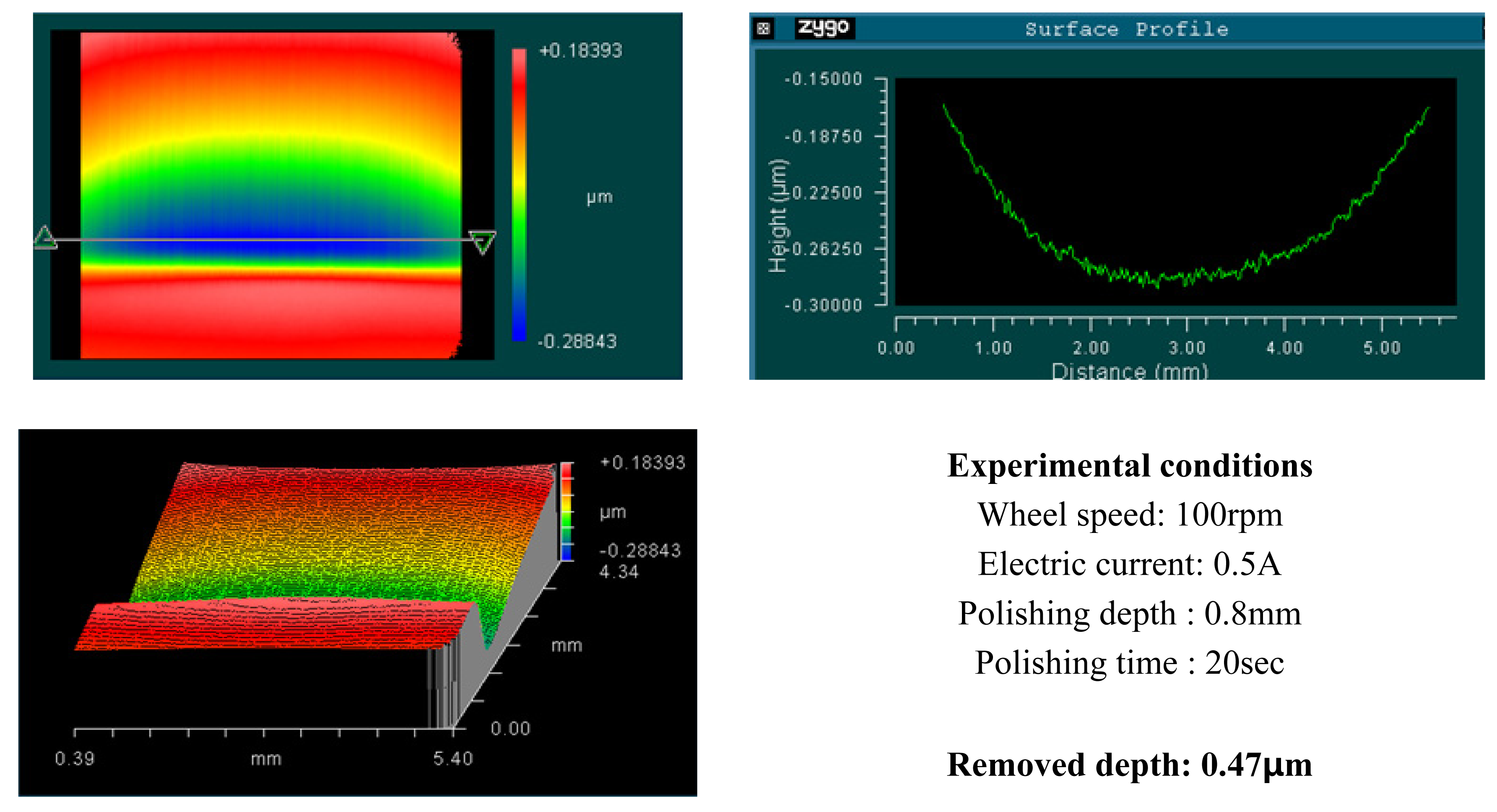
Figure 12.
Measured results after MR polishing using alumina slurry No.3 (100rpm and 2.0A).

Figure 13.
Measured results after MR polishing using alumina slurry No.3 (100rpm and 0.5A).
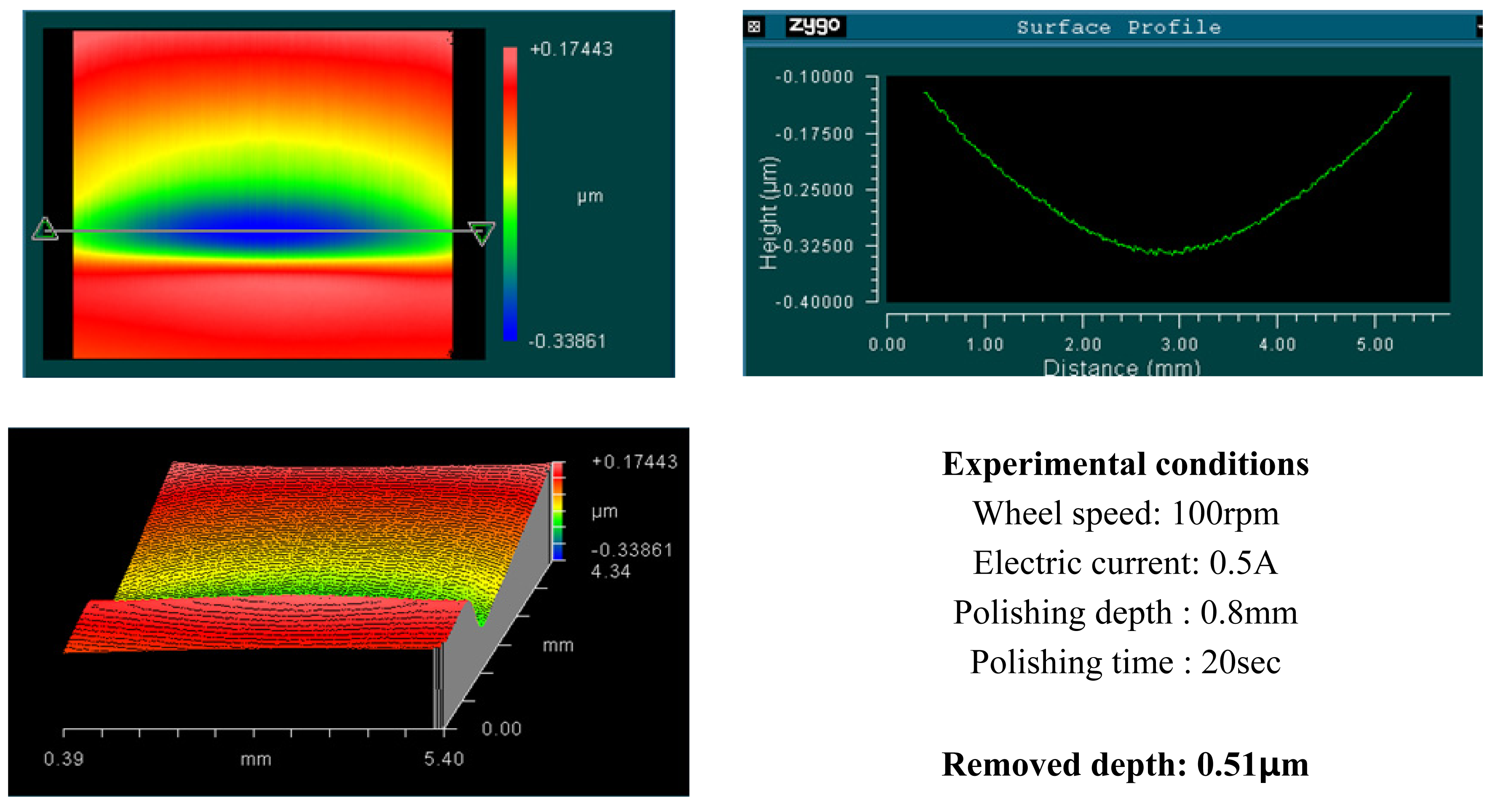
Figure 14.
Measured results after MR polishing using alumina slurry No.4 (100rpm and 2.0A).
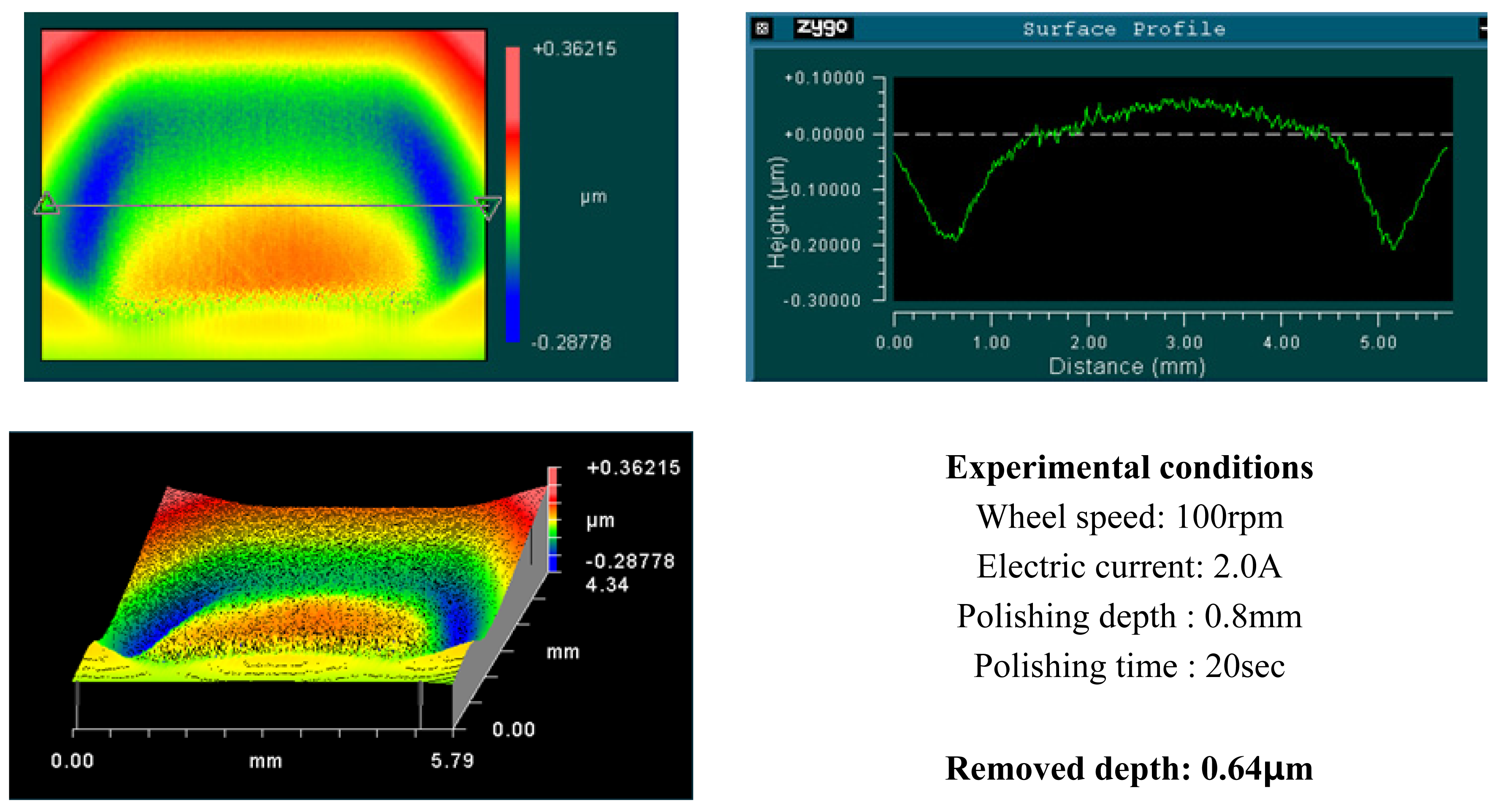
Figure 15.
Measured results after MR polishing using alumina slurry No.4 (100rpm and 0.5A).
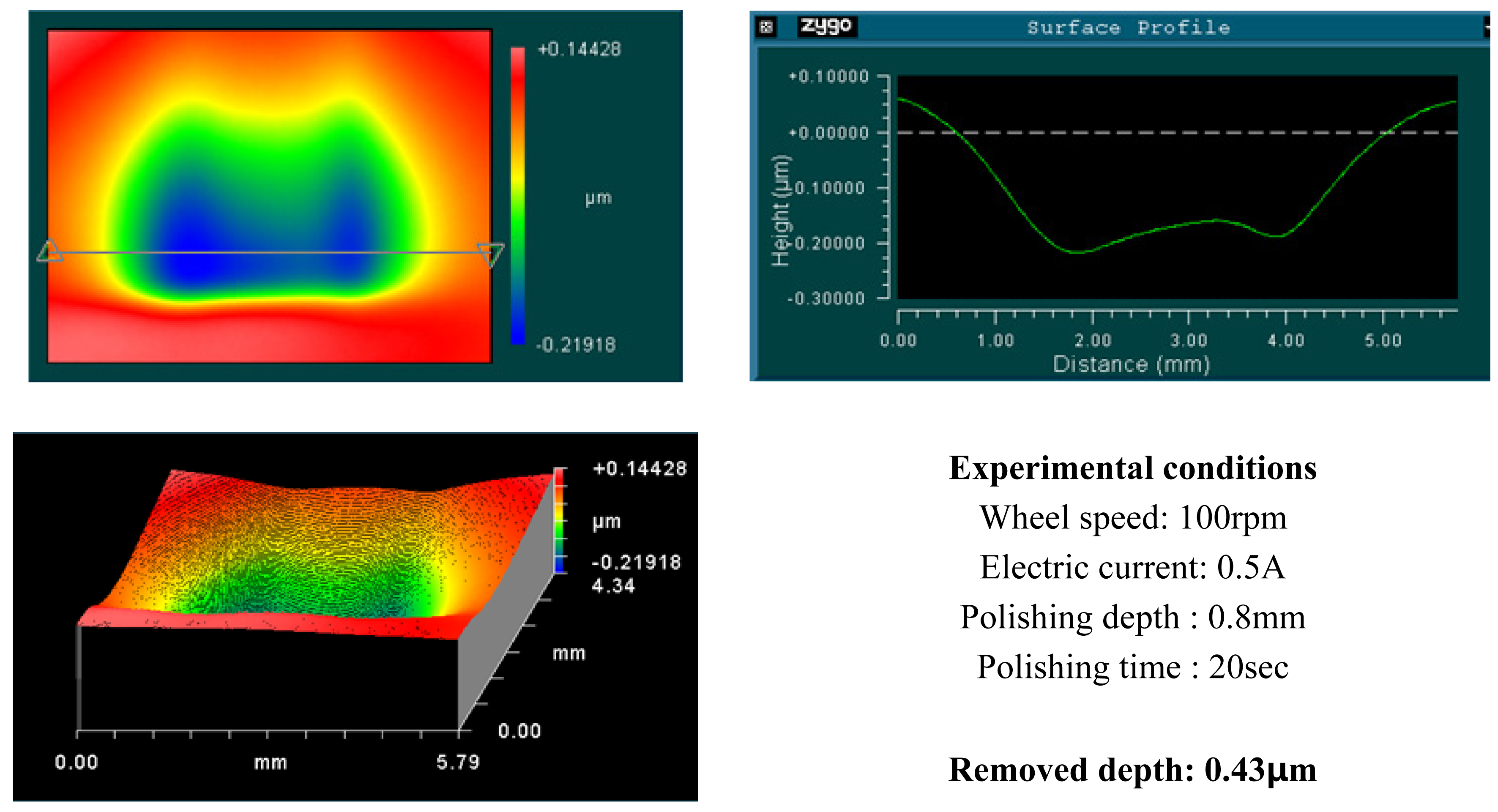
Figure 16.
Image of surface texture generated by surface polishing.

| Structure | Single-crystal cubic c-cut |
| Water solubility | 0.0017 |
| Surface hardness (GPa) | 2.47 |
| Young's module (GPa) | 110 |
| Fracture toughness(KIC) | 0.33 |
| Micro powder iron grade R-2430 | |
|---|---|
| Color | Gray |
| Apparent density | 2.0 - 3.0 |
| True density | 7.7 Maximum |
| Average particle diameter | 4-6 microns |
| % iron | 99.5 max |
| % carbon | 0.05 max |
| % Oxygen | 0.5 max |
| % Nitrogen | 0.1 max |
| Al2O3 | DI water | Glycerol | Na2CO3 |
| 30% | 67.7% | 2% | 0.3% |
| Slurry No. | Slurry condition (wt %) |
|---|---|
| Alumina slurry No.1 | Al2O3 particle(0.05μm) 10% + DI water 88.5% + Glycerin 0.5% + Na2CO3 1% |
| Alumina slurry No.2 | Al2O3 particle 3% + commercial stabilizer(Virgo 222YT-P) 5%+ DI water 92% |
| Alumina slurry No.3 | Al2O3 particle 5% + commercial stabilizer(Virgo 222YT-P) 5%+ DI water 90% |
| Alumina slurry No.4 | Al2O3 particle 10% + commercial stabilizer(Virgo 222YT-P) 5%+ DI water 85% |
| No. | Wheel speed (rpm) | Electric current (A) | Polishing Time | Polishing depth |
|---|---|---|---|---|
| 1 | 100 | 0.5,1,∼ 3 | 20sec | 0.8mm |
| 2 | 150 | 0.5,1,∼ 3 | ||
| 3 | 200 | 0.5,1,∼ 3 | ||
| 4 | 250 | 0.5,1,∼ 3 | ||
| 5 | 300 | 0.5,1,∼ 3 | ||
| 6 | 350 | 0.5,1,∼ 3 |
© 2008 by MDPI Reproduction is permitted for noncommercial purposes.
Share and Cite
MDPI and ACS Style
Kim, D.-W.; Cho, M.-W.; Seo, T.-I.; Shin, Y.-J. Experimental Study on the Effects of Alumina Abrasive Particle Behavior in MR Polishing for MEMS Applications. Sensors 2008, 8, 222-235. https://doi.org/10.3390/s8010222
AMA Style
Kim D-W, Cho M-W, Seo T-I, Shin Y-J. Experimental Study on the Effects of Alumina Abrasive Particle Behavior in MR Polishing for MEMS Applications. Sensors. 2008; 8(1):222-235. https://doi.org/10.3390/s8010222
Chicago/Turabian StyleKim, Dong-Woo, Myeong-Woo Cho, Tae-Il Seo, and Young-Jae Shin. 2008. "Experimental Study on the Effects of Alumina Abrasive Particle Behavior in MR Polishing for MEMS Applications" Sensors 8, no. 1: 222-235. https://doi.org/10.3390/s8010222