Fabrication of Biochips with Micro Fluidic Channels by Micro End-milling and Powder Blasting

Department of Mechanical Engineering, University of Incheon, 177 Dohwa –Dong , Nam-Ku, Incheon, Democratic People's Republic of Korea
*
Author to whom correspondence should be addressed.
Sensors 2008, 8(2), 1308-1320; https://doi.org/10.3390/s8021308
Submission received: 15 February 2008
/
Accepted: 21 February 2008
/
Published: 22 February 2008
(This article belongs to the Special Issue Modeling, Testing and Reliability Issues in MEMS Engineering)
Abstract
:For microfabrications of biochips with micro fluidic channels, a large number of microfabrication techniques based on silicon or glass-based Micro-Electro-Mechanical System (MEMS) technologies were proposed in the last decade. In recent years, for low cost and mass production, polymer-based microfabrication techniques by microinjection molding and micro hot embossing have been proposed. These techniques, which require a proper photoresist, mask, UV light exposure, developing, and electroplating as a pre-process, are considered to have some problems. In this study, we propose a new microfabrication technology which consists of micro end-milling and powder blasting. This technique could be directly applied to fabricate the metal mold without any preprocesses. The metal mold with micro-channels is machined by micro end-milling, and then, burrs generated in the end-milling process are removed by powder blasting. From the experimental results, micro end-milling combined with powder blasting could be applied effectively for fabrication of the injection mold of biochips with micro fluidic channels.
1. Introduction
Microfabrications of biochips with micro fluidic channels have increasingly become important in biomedical and biochemical fields because of their high sensitivity, low cost, and use of smaller volumes of biological samples. For miniaturization and high performance of micro structures and micro devices such as biochips, micro fluidic channels are required, and therefore, the development of effective microfabrication technologies has become a key factor for increasing competitiveness in the related fields. Even though many technologies including ultra-precision micromachining and micro forming have been proposed and developed for fabrication of micro patterns and micro structures, two different kinds of etching techniques are regarded as the most common method of microfabrication: (1) chemical etching technique [1,2] using chemical reaction and (2) mechanical etching technique [3,4] using powder blasting. These techniques are based on photolithography which mainly consists of photoresist coating, UV light exposure and developing.
These days, in order to effectively constitute micro fluidic systems, PDMS (Polydimethylsiloxane), a kind of polymer material, is considered as manufacturing material [5,6,7]. PDMS has several advantages: (1) compatibility with biological or chemical reaction, (2) relatively low price, (3) and suitability for production of simple micro fluidic structures by molding process, a comparatively easy manufacturing process. Molding process of PDMS required micro molds, which were generally fabricated by lithography processes. These processes require a proper photoresist, mask, UV light exposure, developing, and electroplating, and therefore, problems related to these processes still need to be solved.
In order to overcome these problems for mass-production, this study presents a manufacturing injection mold for biochips with micro-fluidic channels by using micro end-milling and powder blasting techniques. Almost all techniques mentioned above require certain pre-processes but the technique proposed in this study makes micro channels directly on the surface of metal materials through micro end-milling and removes micro burrs formed at the channel edges in end-milling process through powder blasting.
Micromachining technology like micro end-milling has been developed through realization of ultra precision and ultra high speed machining, but minute burr formations [8,9] generated during micromachining were not considered as an important problem. Micro burrs can cause serious packaging problems of micro parts like LOC (lab-on-a-chip). Moreover, micro burrs can deteriorate the flow inside micro channels and the biochip performance. It is not easy to avoid micro burr formations in the micromachining process; consequently, an effective deburring technology has become very important. General deburring processes consist of mechanical technology using abrasives, barrels or brushes; chemical technology using etching; and other technologies using ultrasonic and electro-polishing [10,11].However, effective deburring technologies for micro patterns and micro structures have not been proposed yet.
By applying the powder blasting process, frequently introduced for mechanical etching for brittle materials [12,13,14], this paper proposes a deburring technique that can effectively remove micro burrs formed at the edges of micro fluidic channels in micro end-milling. In experiments, several factors of powder blasting process were considered as parameters to optimize the deburring processes. Through a series of experiments, optimal machining conditions were obtained.
2. Micromachining System
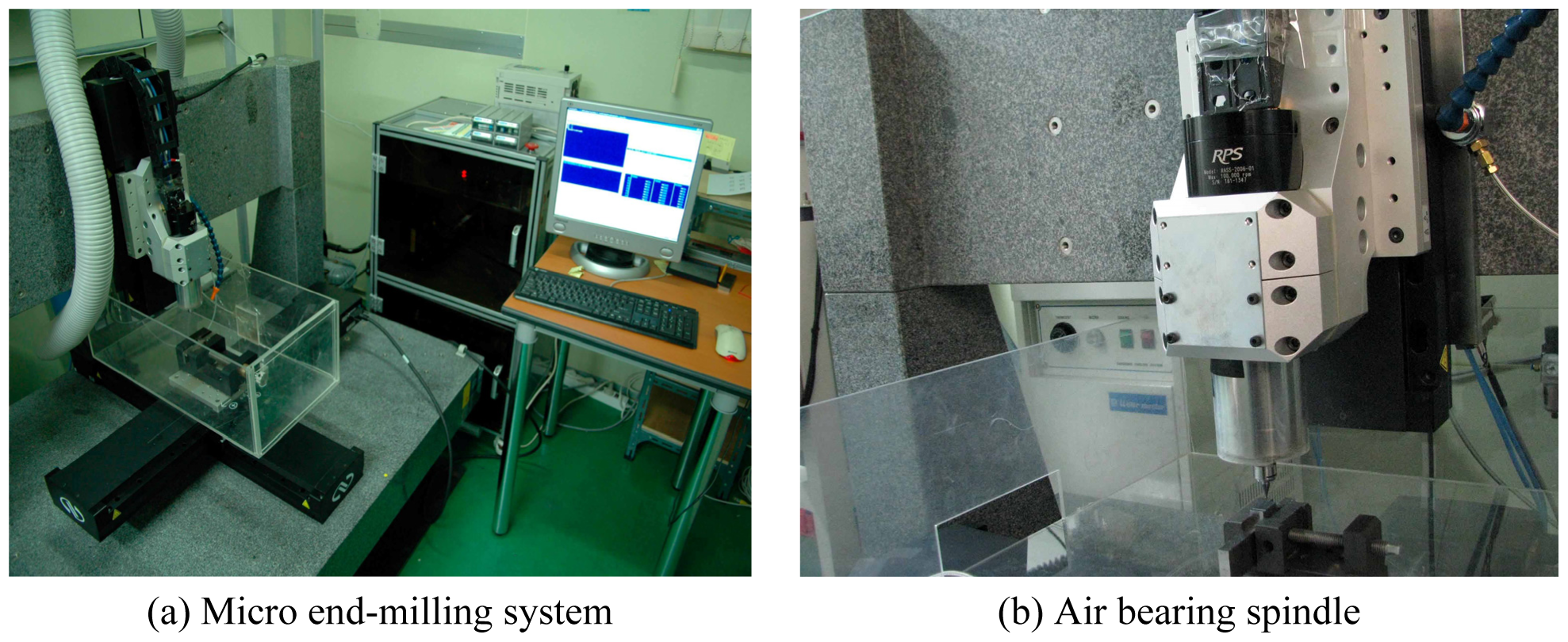
Figure 1 shows the micromachining system used in the experiment. This system was designed and developed for micro end-milling using rotating tools and the micro U or V grooving using single crystal diamond tools. This system consists of an air bearing spindle, and three linear stages. The maximum rotating speed of spindle is 100,000 rpm. Three linear stages, which have a long traveling range, are used for a large scale mold with micro patterns or shapes. All linear stages have linear built-in scale and are operated by DC servo motors. For isolating the vibration from the floor, this system is supported with four air isolators. Specifications of this system are shown in Table 1.
3. Powder Blasting
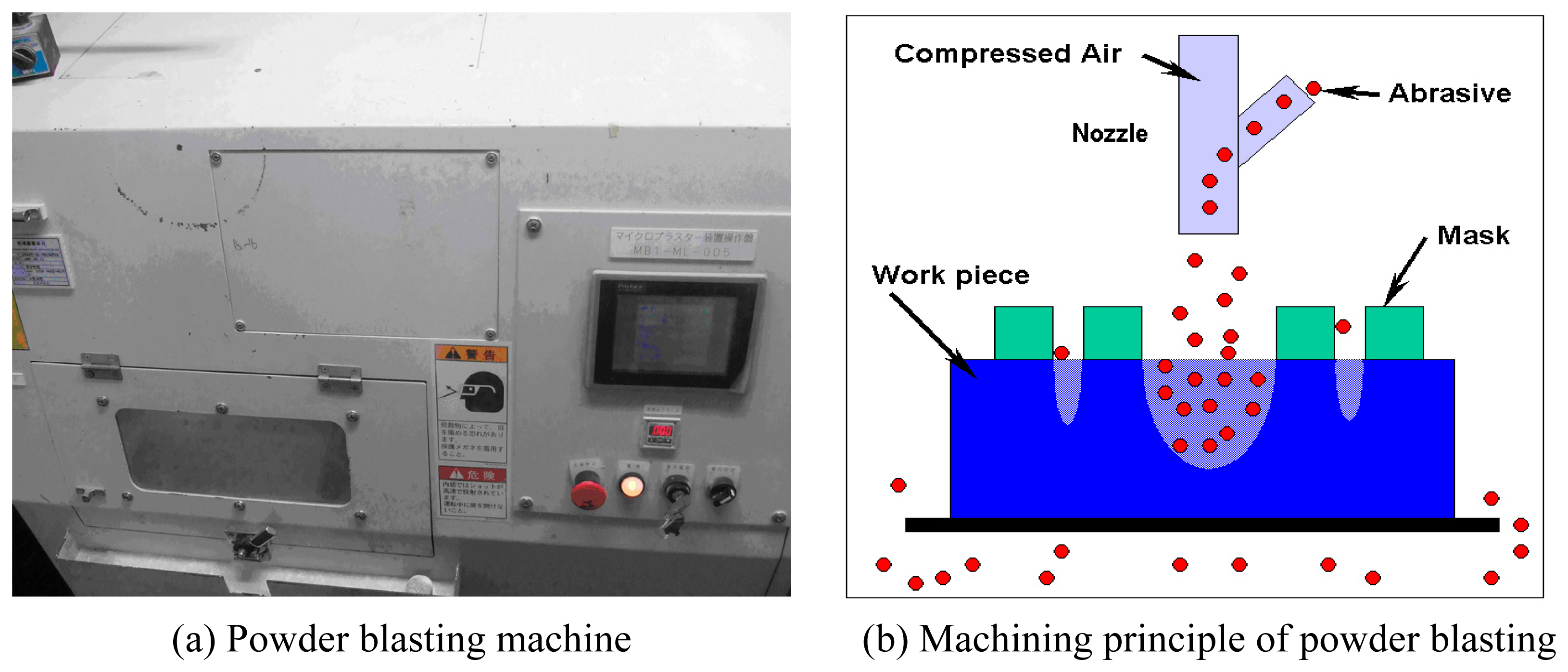
The powder blasting process is similar to those of abrasive jet machining. However, powder blasting can be classified into another process when it is applied to machine micro shapes of size below 100 μm with very small micro powders. In the process, the micro powders are accelerated by highly compressed air or gases, and collide with the workpiece at very high velocity. Thus, this process is capable of performing micromachining by the integration of the brittle mode based on micro crack propagation. Figure 2 shows the basic micromachining principle of powder blasting. The removal process is carried out by scanning the blasting nozzle along pre-defined paths on the workpiece covered with a mask or photoresist materials. Since the machined workpiece shape is determined by the mask pattern, very complex and/or micro shapes can be easily obtained.
The parameters used to define the powder blasting process are blasting pressure, material properties, size and mass flow rate of the abrasives, number of times and speed of the nozzle scanning, and distance between the nozzle and workpiece. Such parameters should be appropriately determined to improve the machining accuracy and efficiency. Basically, since the powder blasting process is performed by utilizing micro erosion caused by the collision of each micro abrasive, only small amounts of chipping, crack, and heat are generated. Thus, this process is suitable for the micromachining of hard and brittle materials such as glass, ceramics, silicon, and crystals.
4. Experimental Method
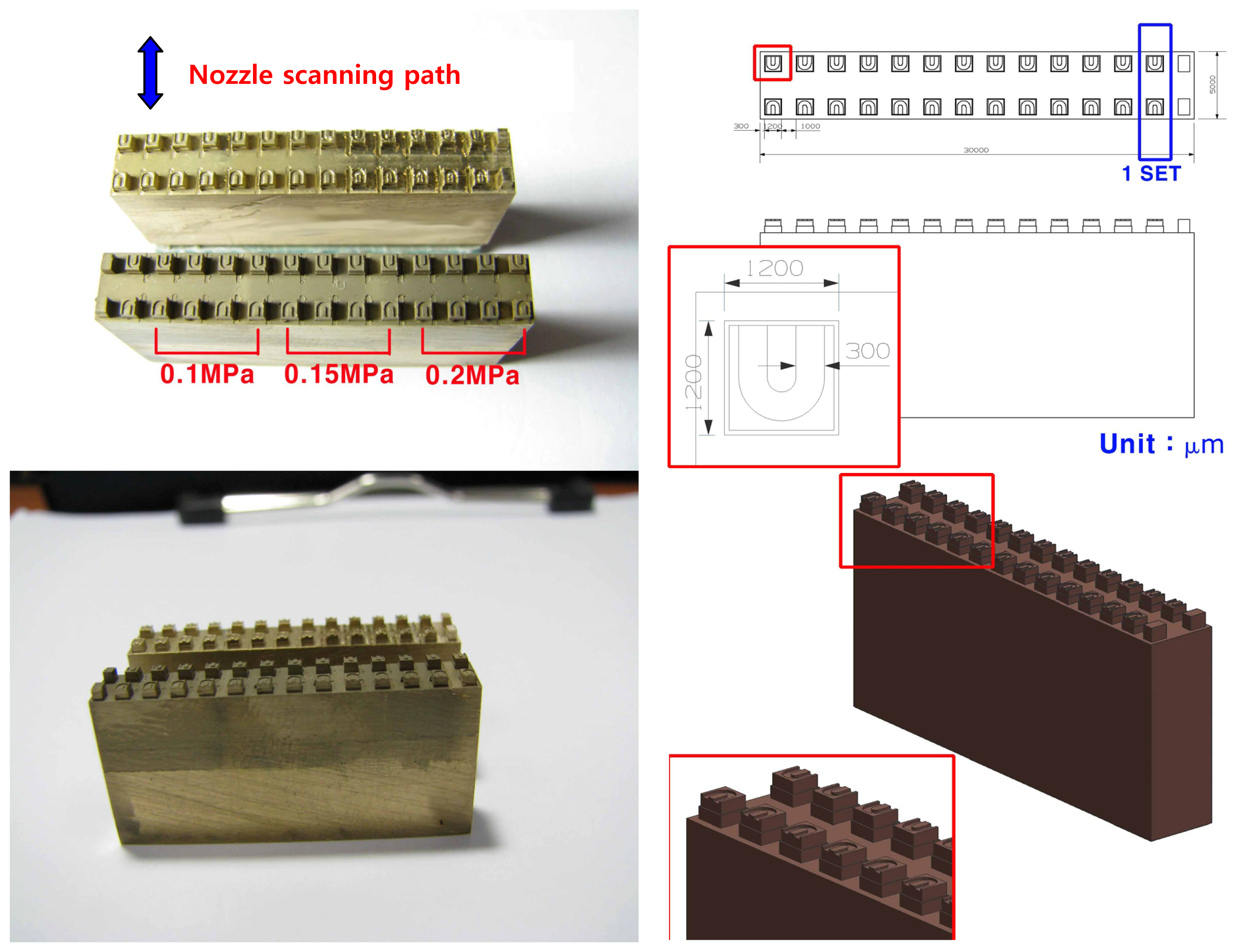
In the experiments, brass was used as the material of the main specimen, of 30 mm × 5 mm × 15 mm in size. As shown in Figure 3, 26 rectangular poles (13 pairs) were machined by micro end-milling and then U-shaped micro fluidic channel, sized as 300 μm (width) × 100 μm (depth), was machined on each rectangular pole. The cutting conditions of micro end-milling are provided in Table 2. The cutting tool corresponds to 300μm-diameter and 2-flute flat end-mill. 300 mm/min-feedrate, 40,000 rpm-spindle rotational speed, and 100 μm-axial depth of cut were taken into account.
First, micro burrs produced in the vicinity of the U-shaped micro fluidic channel through micro end-milling were observed and analyzed by SEM (Scanning Electron Microscope). In order to remove these micro burrs, powder blasting processes were applied on all the surfaces of the U-shaped micro fluidic channels at different machining conditions. The ultimate purpose of the powder blasting is to looking for optimized deburring conditions such that the channel edge shapes remain as sharp as possible after powder blasting. Thus, different powder blasting conditions were applied on each pair of U-shaped micro fluidic channels. A protection cover of the specimen was used to protect other U-shaped channels when powder blasting was applied on a specific channel. Figure 4 shows this protection cover of the specimen and the installation method.
Powder blasting processes for deburring were carried out under machining conditions shown Table 3. The powder materials were WA #600 (white fused alumina(WA), and grain size of powder #600) and WA #1000. The powder blasting pressure was varied as 0.1MPa, 0.15MPa and 0.2MPa.
The mass flow rate of the powder was 100g/min and the nozzle scanning pitch was 5mm. X- and Y-directional feedrates of the table were maintained at 100mm/sec. The diameter of the nozzle was 8mm, and the distance between the nozzle and specimen was maintained at 100 mm. The number of scanning was increased from 2 until 30 at an increment of 2 for every single pair of micro channels. Nozzle scanning path is shown in Figure 3.
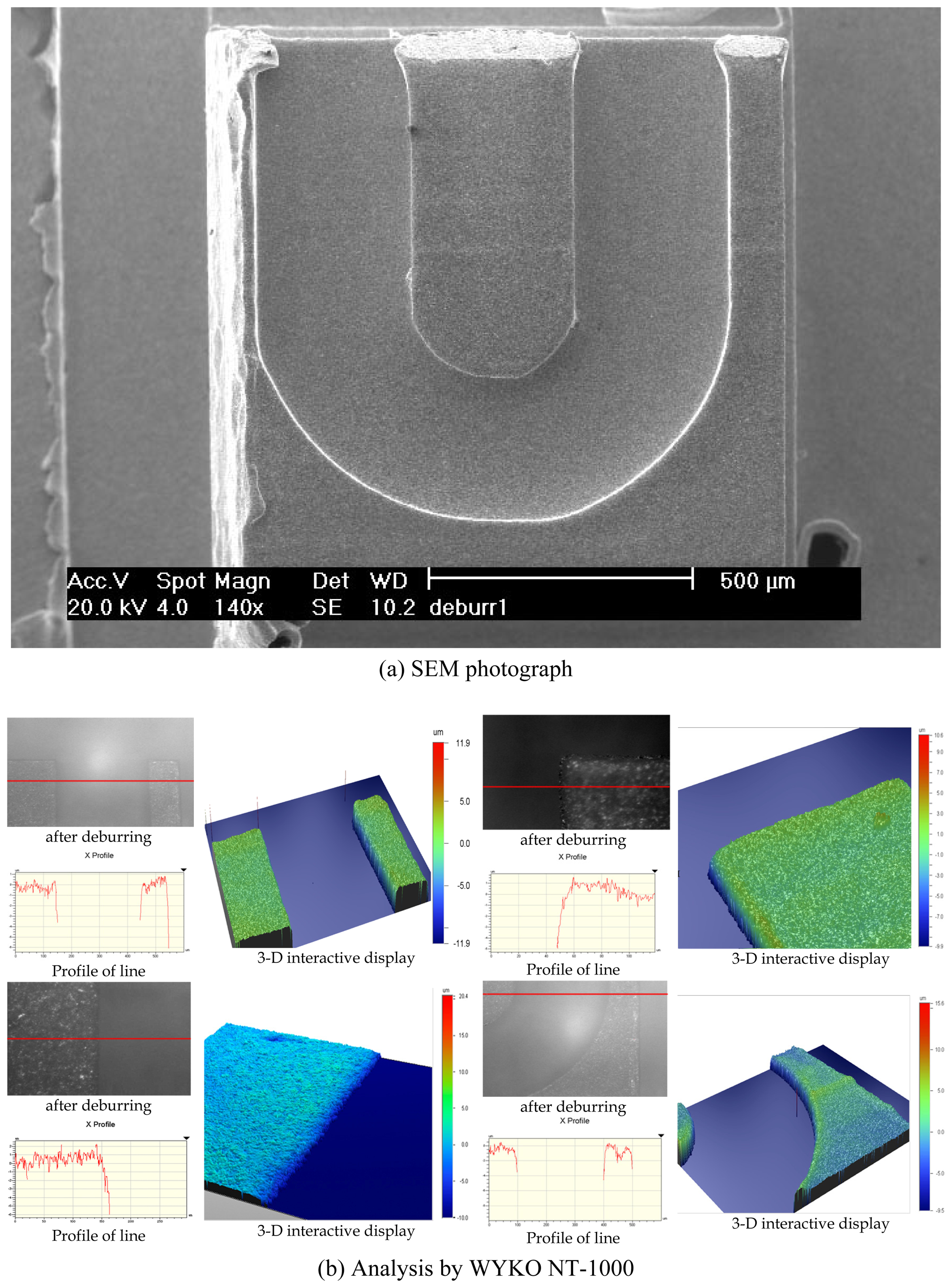
After the experiments, deburring characteristics were observed by SEM and analyzed by non-contact type optical 3-dimensional profile measurement equipment (Veeco, WYKO NT-1000).
5. Result and Discussion
The specimen shown in Figure 3 was observed before/after deburring. The machined micro channels and micro burrs were also observed and analyzed by SEM and the WYKO NT-1000.
5.1 In case of blasting pressure 0.2MPa
Figure 5 shows an SEM photograph of a micro channel after micro end-milling. Excessive micro burrs were generated all over the channel edge. When deburring with blasting pressure of 0.2MPa, powder WA #600 and scanning times 2, the desired deburring results were obtained. These results are shown in Figure 6(a). Because of the excessive impacts of powder particles, nevertheless, innumerable pockmarks appeared on the surface of the specimen, and the sharp edges of micro channel were collapsed. It was difficult to obtain an optimized surface state after powder blasting with WA #600. These pockmarks and edge collapse became more severe when the scanning time was increased. However, when deburring was performed with WA #1000, an optimized surface state was obtained after 10 scannings, as shown in Figure 6(b). The pockmarks, which appeared previously on the surface of the specimen, and the sharp edge collapses were remarkably reduced. However, at blasting pressure of 0.2MPa, it was difficult to adjust the number of scanning to maximize the efficiency of the deburring process.
5.2 In case of blasting pressure 0.15MPa
Figure 7 shows a SEM image of the micro channel just after end-milling before deburring and the surface analysis results obtained by using WYKO NT-1000. Excessive micro burrs appeared just after micro end-milling. Figure 8(a) shows an SEM image of the micro channel of the specimen of Figure 7 just after deburring with powder WA #600 at the blasting pressure 0.15MPa, for 4 scans, and Figure 8(b) shows the surface analysis results of this specimen. In this case, as a whole, the deburring process was effectively carried out. However, when powder WA #600 was used, innumerable pockmarks appeared on the surface of the specimen as mentioned above, and surface roughness was not proper because the powder particle size was unsuitably large. As shown in the 3-D display of Figure 8(b), the sharp edges of the micro channel collapsed.
Figure 9 shows the deburring results when blasting with powder WA #1000 at the blasting pressure of 0.15MPa, for 20 scans. In this case, deburring process was effectively carried out, showing almost no appearance of improper surface roughness, innumerable pockmarks and sharp edge collapse, which appeared in the case of powder WA#600. Based on the results of Figure 6 and Figure 9, deburring processes with WA #1000 were found to be more effective than those with WA #600 for obtaining proper surface roughness.
Through the overall deburring experiments, when carrying out deburring with powder WA #1000, the blasting pressure of 0.15MPa and 20 scans could be the best conditions for sharp edges of good shape. In the case of blasting pressure 0.20MPa, 10 scans were found to yield the best deburring. These two cases could give satisfactory results; however, blasting at low pressure for more number of scans could yield more suitable deburring. When carrying out deburring with powder WA #600, the blasting pressure of 0.15MPa and 4 scans could be the best for good deburring and edge shape; at the blasting pressure of 0.20MPa and 2 scans, good deburring and edge shape could be also obtained. In these two cases, deburring efficiency was good, but micro pockmarks could not be avoided, deteriorating surface roughness. With more number of scans than those of the above cases, the surface roughness was not affected, but channel edge collapses increased.
On the other hand, micro pockmarks inside the micro channels of biochips can make fluidic matters become turbulent; consequently, sample solutions can be easily mixed. In this respect, in order to make pockmarks on the surfaces of micro channels, as shown in Figure 6(a) or Figure 8, the deburring process should be carried out with bigger powder particles of WA #600.
When deburring was carried out at the blasting pressure of 0.1MPa, micro burrs could not be removed, regardless of the powder particle size. Because this blasting pressure could not trasfer significant impact energy to the powder particles, results of experiment for the blasting pressure of 0.1MPa are not shown here.
From the experimental results mentioned above, micro fluidic channels could be manufactured for biochips by an efficient overall process consisting of two processes: (1) machining of basic shapes by micro end-milling as a pre-process (2) and removing of micro burrs by powder blasting as a post-process. Basic channel geometry machined by end-milling is not changed after deburring process using powder blasting, except that micro pockmarks appear on the surface of a channel. Therefore, this approach could be applied to directly manufacture biochips and injection molds for biochip mass production. Moreover, by controlling the powder particle size of the deburring process, deburring effect as well as mixing effect by turbulence induced by pockmarks could be expected.
6. Conclusion
This study proposed a new microfabrication technology for LOC or biochips with micro fluidic channels. First, micro channels were directly machined by micro end-milling and then micro burrs inevitably formed at the channel edges are removed by powder blasting process. For verification of the proposed approach, a series of experiments were carried out. U-shaped micro fluidic channels, sized 300μm (width) × 100μm (depth), were micromachined effectively by using micro-endmilling. In the deburring process using powder blasting, the powder particle size, blasting pressure and nozzle scanning times were shown to be important parameters determining the deburring characteristics, edge shape, and surface roughness of a micro channel. The optimum deburring conditions for good surface roughness and edge shape of micro channels were as follows: blasting pressure of 0.15MPa, powder WA #1000 and 20 scans. From the overall experimental results, micro end-milling together with powder blasting could be an effective technique for the fabrication of micro fluidic channels.
Acknowledgments
This work was supported by the University of Incheon Research Grant in 2007.
References
- Mouradian, S. Lab-on-a-chip: Applications in proteomics. Current opinion in chemical biology 2002, 6, 51–56. [Google Scholar]
- Tseng, F.G.; Chuang, Y.J.; Lin, W.K. A novel fabrication method of embedded micro channels employing simple UV dosage control and antireflection coating. IEEE 15th International Conference on Micro Electro Mechanical Systems 2002, 69–72. [Google Scholar]
- Belloy, E.; Thurre, S.; Walckiers, E.; Sayah, A.; Gijs, M.A.M. The introduction of powder blasting for sensor and microsystem applications. Sensors and Actuators A: Physical 2000, 84, 330–337. [Google Scholar]
- Solignac, D.; Sayah, A.; Constantin, S.; Freitag, R.; Gijs, M.A.M. Powder blasting for the realisation of microchips for bio-analytic applications. Sensors and Actuators A: Physical 2001, 92, 388–393. [Google Scholar]
- Jo, B.H.; Van Lerberghe, L.M.; Motsegood, K. M.; Beebe, D. J. Three-dimensional microchannel fabrication in polydimethylsiloxane(PDMS) elastomer. Journal of Microelectromechanical Systems 2000, 9, 76–81. [Google Scholar]
- Chung, G.S.; Woo, H. S. Fabrication of SiCN microstructures for super-high temperature MEMS using PDMS mold and its characteristics. Journal of the Korean Sensors Society 2006, 15, 53–57. [Google Scholar]
- Chien, R.D. Micromolding of biochip devices designed with microchannels. Sensors and Actuators A: Physical 2006, 128, 238–247. [Google Scholar]
- Lee, K.; Dornfeld, D.A. Micro-burr formation and minimization through process control. Precision Engineering 2005, 29, 246–252. [Google Scholar]
- Lee, K.; Dornfeld, D. A. An experimental study on burr formation in micro milling aluminum and copper. Technical paper - Society of Manufacturing Engineers. AD. 2002, 202. ALL-. [Google Scholar]
- Ko, S.L.; Baron, Y. M.; Park, J. I. Micro deburring for precision parts using magnetic abrasive finishing method. Journal of Materials Processing Technology 2007, 187, 19–25. [Google Scholar]
- Yeo, S.H.; Ngoi, B. K. A.; Chua, L. Y. Ultrasonic Deburring. International Journal of Advanced Manufacturing Technology 1997, 13, 333–341. [Google Scholar]
- Slikkerveer, P.J.; Bouten, P. C. P.; de Haas, F. C. M. High quality mechanical etching of brittle materials by powder blasting. Sensors and Actuators A: Physical 2000, 85, 296–303. [Google Scholar]
- Park, D.S.; Yun, D. J.; Cho, M. W.; Shin, B. C. An Experimental Study on the Fabrication of Glass-based Acceleration Sensor Body Using Micro Powder Blasting Method. Sensors 2007, 7, 697–707. [Google Scholar]
- Park, D.S.; Seo, T. I.; Cho, M. W. Mechanical etching of micro pockets by powder blasting. International Journal of Advanced Manufacturing Technology 2005, 25, 1098–1104. [Google Scholar]
Figure 1.
Micromachining system.

Figure 2.
Powder blasting machine and machining mechanism.

Figure 3.
Experimental specimen for micro end-milling.

Figure 4.
Protection cover for micro channel set.
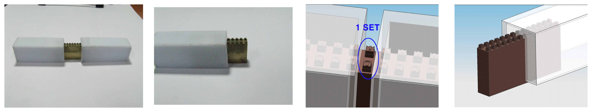
Figure 5.
SEM photograph of a micro fluidic channels machined by micro end-milling.
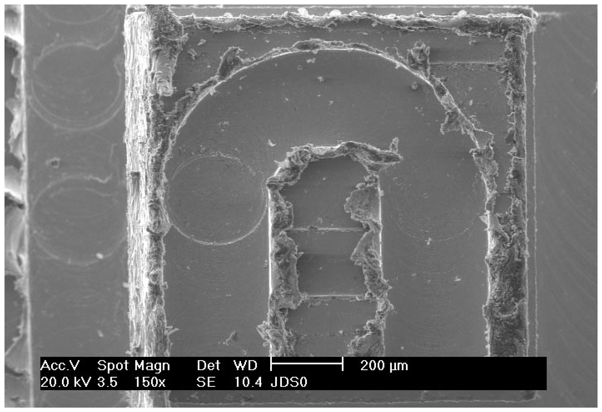
Figure 6.
SEM photograph of micro fluidic channels after deburring.
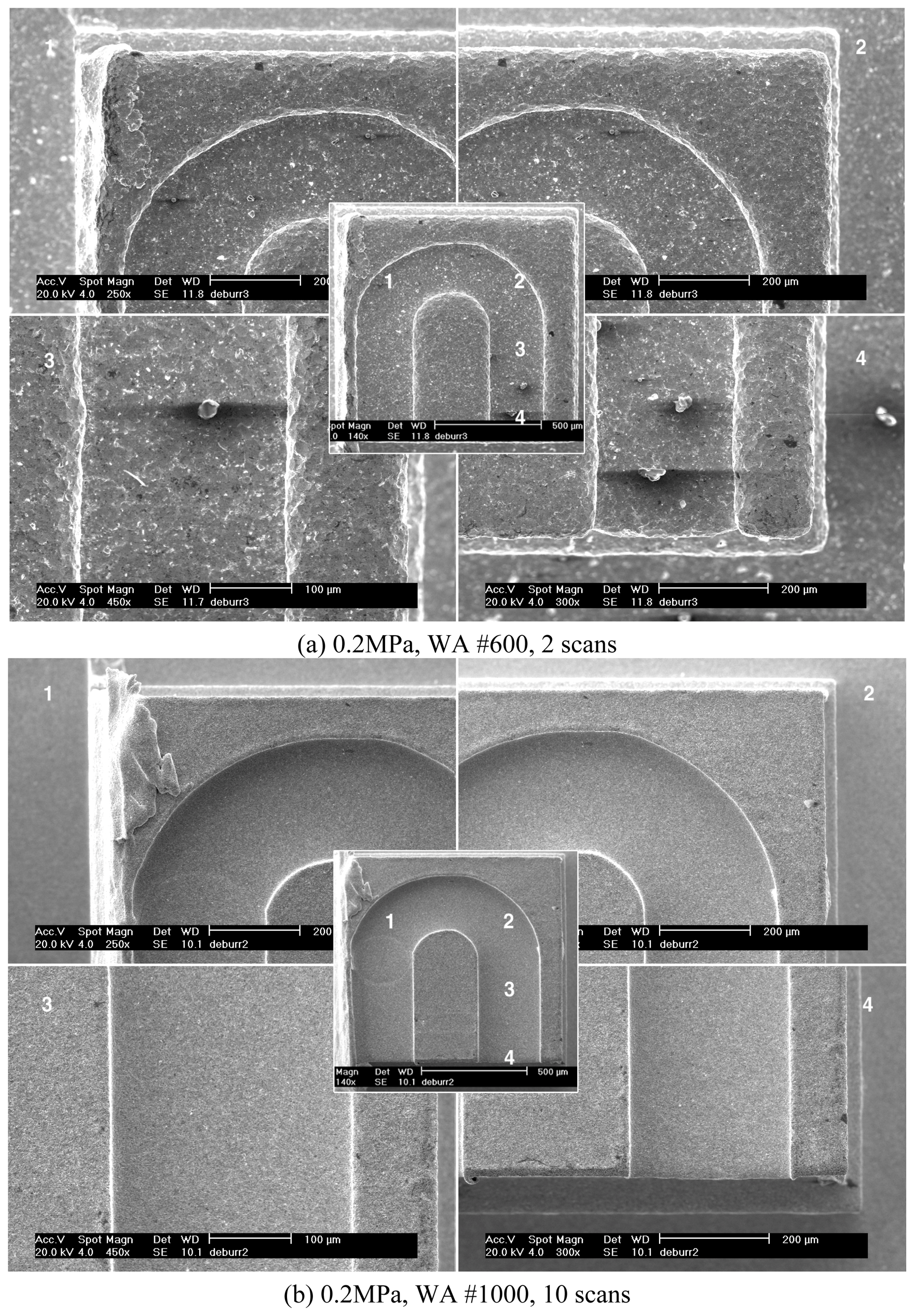
Figure 7.
Shapes and analysis of micro fluidic channels machined by micro end-milling.
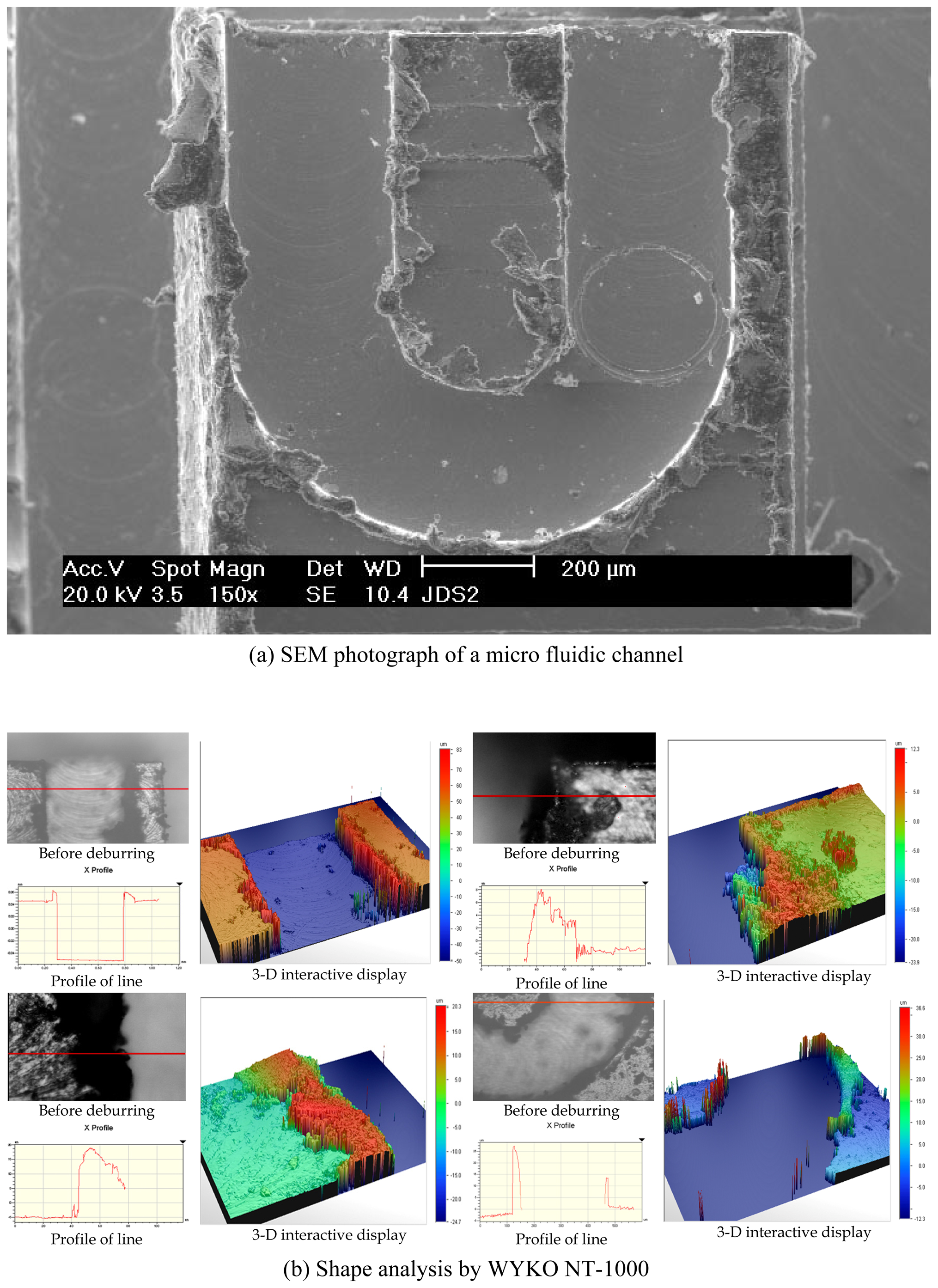
Figure 8.
Micro-fluidic channels after deburring by the powder WA #600, 4 scans.
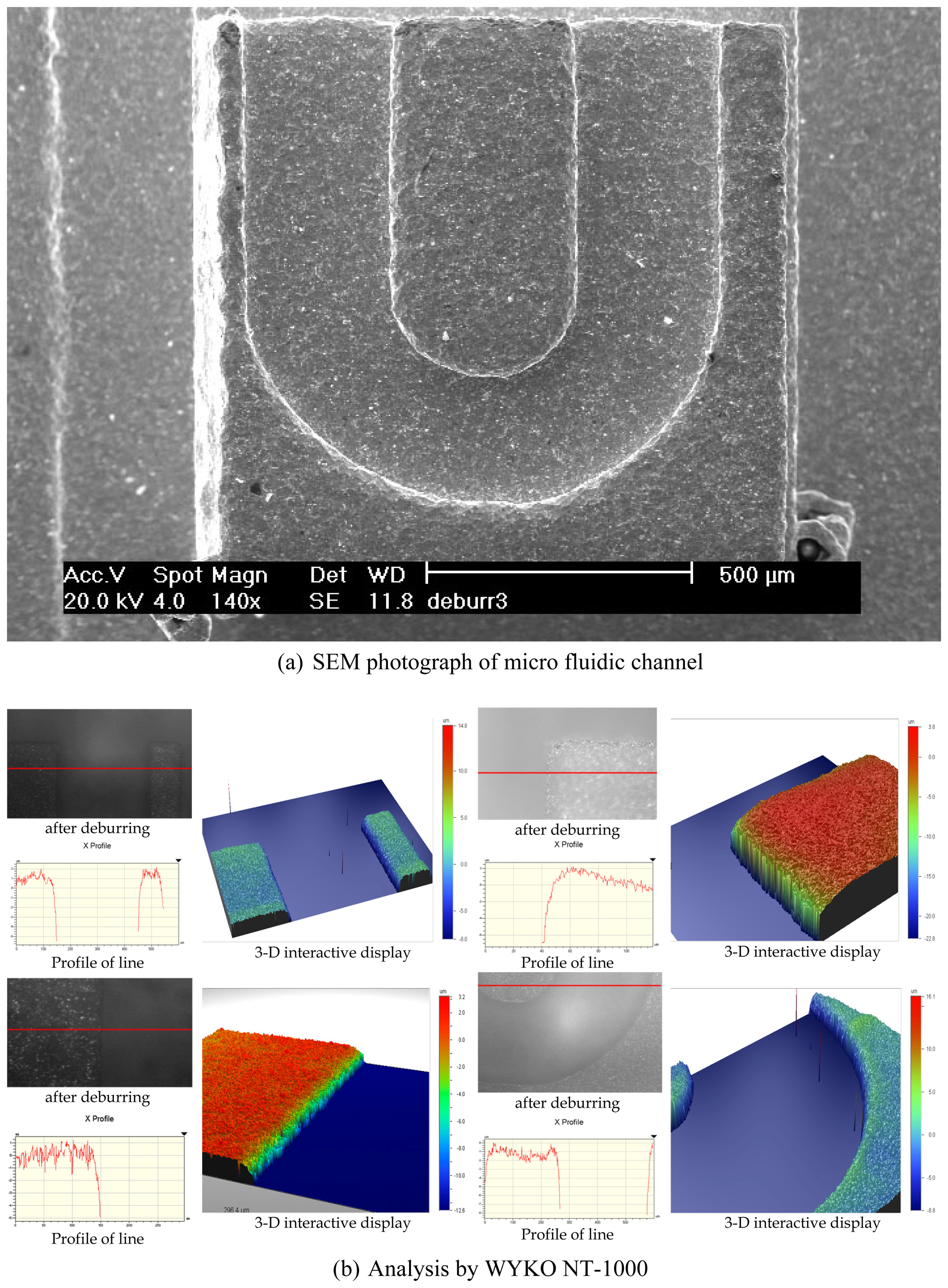
Figure 9.
Micro-fluidic channels blasted for deburring by the powder WA #1000, 20 scans.

| Traveling range | 600×600×200 mm | Rotational speed | Max. 100,000 rpm |
| Resolution | 0.1 μm | Spindle run-out | Max. 0.7 μm |
| Accuracy | X, Y: 6 μm, Z: 2 μm | Static radial load | Min. 58.8 N |
| Repeatability | 0.2 μm | Lubrication | Dry cutting |
| Max. velocity | X, Y: 200 mm/s, Z: 100 mm/s | Workpiece weight | Max. 440 N |
| Feedrate of table | 300 mm/min |
| Spindle rpm | 40,000 rpm |
| Axial depth of cutting | 100 μm |
| Tool | φ300 μm, 2-flute flat end-mill |
| Specimen material | 6:4 Brass |
| Powder | WA #600, WA #1000 |
| Blasting pressure | 0.1, 0.15, 0.2 MPa |
| Stand-off distance | 100 mm |
| Impact angle | 90° |
| Mass flow rate | 100 g/min |
| Feed of table | X, Y: 100 mm/sec |
| Scanning times | 2 ∼ 30 times |
© 2008 by MDPI Reproduction is permitted for noncommercial purposes.
Share and Cite
MDPI and ACS Style
Yun, D.J.; Seo, T.I.; Park, D.S. Fabrication of Biochips with Micro Fluidic Channels by Micro End-milling and Powder Blasting. Sensors 2008, 8, 1308-1320. https://doi.org/10.3390/s8021308
AMA Style
Yun DJ, Seo TI, Park DS. Fabrication of Biochips with Micro Fluidic Channels by Micro End-milling and Powder Blasting. Sensors. 2008; 8(2):1308-1320. https://doi.org/10.3390/s8021308
Chicago/Turabian StyleYun, Dae Jin, Tae Il Seo, and Dong Sam Park. 2008. "Fabrication of Biochips with Micro Fluidic Channels by Micro End-milling and Powder Blasting" Sensors 8, no. 2: 1308-1320. https://doi.org/10.3390/s8021308