Micro Dot Patterning on the Light Guide Panel Using Powder Blasting

1
Dept. of Mechanical Engineering, Univ. of Incheon, 177 Dohwa –Dong , Nam-Ku, Incheon, Korea
2
Division of Mechanical Engineering, Inha University, Incheon 402-751, Korea
*
Author to whom correspondence should be addressed.
Sensors 2008, 8(2), 877-885; https://doi.org/10.3390/s8020877
Submission received: 10 January 2008
/
Accepted: 6 February 2008
/
Published: 8 February 2008
(This article belongs to the Special Issue Modeling, Testing and Reliability Issues in MEMS Engineering)
Abstract
:This study is to develop a micromachining technology for a light guide panel(LGP) mold, whereby micro dot patterns are formed on a LGP surface by a single injection process instead of existing screen printing processes. The micro powder blasting technique is applied to form micro dot patterns on the LGP mold surface. The optimal conditions for masking, laminating, exposure, and developing processes to form the micro dot patterns are first experimentally investigated. A LGP mold with masked micro patterns is then machined using the micro powder blasting method and the machinability of the micro dot patterns is verified. A prototype LGP is test- injected using the developed LGP mold and a shape analysis of the patterns and performance testing of the injected LGP are carried out. As an additional approach, matte finishing, a special surface treatment method, is applied to the mold surface to improve the light diffusion characteristics, uniformity and brightness of the LGP. The results of this study show that the applied powder blasting method can be successfully used to manufacture LGPs with micro patterns by just single injection using the developed mold and thereby replace existing screen printing methods.
1. Introduction
The light guide panel(LGP) is a key component of the backlight unit(BLU) which transforms the linear light source of a cold cathode fluorescent lamp(CCFL) to uniform planar light source. For this optical transformation, screen printing methods are generally used to form micro patterns on one surface of the injected panel. The micro patterns are composed of several tens of thousands circular or rectangular dots having a maximum diameter or width of 150-180μm and height of roughly 10μm. However, this screen printing process, which should be directly applied to each injected LGP for micro dot formation, causes low productivity and low reproducibility in TFT-LCD manufacturing. Therefore, attempts are being made to develop the LGP manufacturing methods without a screen printing process.
The purpose of this study is to develop precision mold machining technologies required for LGP injection mold manufacturing processes that circumvent the need for screen printing. To this end, micro powder blasting process [1-9] is applied to fabricate micro dot-patterned injection mold. A series of experiments are performed to determine the optimum machining conditions for micro pattern formation on the LGP surface. After machining the required mold, test injections are performed. Machined and injected micro patterns are measured and investigated to verify the feasibility of application of the developed technologies. In order to improve uniformity and brightness of the light emitted from LGP, matte treatment, a special surface treatment method, is applied and the results are investigated.
2. Basic structure of a light guide panel
2.1 Components of a TFT-LCD
A typical TFT-LCD is composed of a LCD panel and a BLU. The BLU is composed of several parts, as shown in Figure 1 and the most important being the LGP, which is generally injected by injection mold using PMMA(polymethyl methacrylate). The main function of the LGP is to transform linear light source of a CCFL to uniform planar light via micro dots formed on the LGP. Generally, the dot size and its density varies from place to place according to the makers. The brightness and uniformity of a TFT-LCD depends strongly on these micro dot patterns. Also, it is known that smaller dots offer better brightness and uniformity.
2.2 Existing dot pattern making processes
Dot pattern forming technologies for LGPs can be categorized according to the LGP type(direct type, side light type) as follows:
- (a)
- Screen printing : This is the most generally adopted method for micro pattern formation on LGPs. Patterns are formed using a screen printing method on a PMAA panel with ink(SiO2, Al2O3, TiO2, etc.). Pattern height can be controlled by the numbers of screen printing. This method has advantages of short developing time, high productivity and low cost and disadvantages of low brightness compared to other methods.
- (b)
- Injection using etched mold : In this method, patterns are formed on the mold by chemical etching. Using the etched mold, patterns can then be formed on the LGP via an injection process. Etched depth varies according to the concentration of chemical solution and etching time. Since it is difficult to control the etched depths, this method has some disadvantages including difficulties to produce uniform molds, irregular light dispersion, and ejection problems caused by over-etching.
- (c)
- Mechanical machining : This method uses machine tools to form micro grooves on a flat type LGP. Brightness can be controlled by the groove density on the LGP. Grooves can be machined either on the LGP directly or on a mold. While this method can deliver high brightness, long machining time is required. Other drawbacks are that groove depth control is difficult due to tool wear and deformation can occur due to applied mechanical force.
- (d)
- Injection using abrasive jet machined mold : This method adopts micro abrasive jet machining techniques to form patterns on the LGP mold. Several research results have been reported for limited cases; however, only a few practical application cases have been reported thus far. This method is expected to offer high productivity.
3. Mold machining process conditions
3.1 Machining properties of micro powder blasting
Machining properties of micro powder blasting are similar to those of abrasive jet machining methods. Powder blasting is regarded as a mechanical etching process. In this process, micro abrasives(tens of μm) are accelerated by highly compressed air or gases, and collide with the workpiece with very high velocity(80 – 200m/s). Thus, this process can be employed to perform micromachining by the integration of brittle mode fractures based on micro crack propagation. Material removal can be performed by scanning the blasting nozzle along pre-defined paths on the workpiece covered with a photoresist film. Since the machined workpiece shape can be determined by the mask pattern, very complex and/or micro shapes can be easily obtained. The main parameters used to define the powder blasting process are blasting pressure, blasting velocity, material properties, size and density of the abrasives, number of iterations and velocity of the nozzle scanning and standoff distance between the nozzle and workpiece, etc.
3.2 Applied machining process
The overall fabrication process for a LGP mold with micro pattern using powder blasting is illustrated in Figure 2. Prior to this process, pattern design and pattern mask making processes are required. Through the masking process, mold regions to be removed by the powder blasting are determined. Finally, the desired micro dot pattern forming injection mold for the LGP can be obtained after the powder blasting and cleaning processes.
In this study, optimum masking conditions are determined based on experimental results. The thickness of the used mask film is 40μm(BF704, Ordyl, Japan), and the applied laminating temperature is maintained at 80°C. The exposure is 250mJ using a parallel UV beam, and developing is performed with a 5% NaCO3 solution and a 15 minute softbaking process is followed. The optimum blasting conditions for mold machining are determined based on a series of experiments, as shown in Table 1.
4. Machining results and analysis
4.1 Specimen shapes after masking
Examples of masked square-type patterns on a mold specimen are shown in Figure 3. Patterns are related with the density of square shapes in the mold, which are designed and determined considering the optical characteristics of the LGP. In Figure 3, (a), (b), and (c) are top, middle, and bottom sections of the masked patterns, respectively. It can be observed that square patterns are clearly formed throughout the mold specimen. Each square, which will be dot patterns of the injected LGP, is to be machined using powder blasting. However, as shown in Figure 3(c), minute blurs can be seen around some marginal regions of the patterns. Such blurs are an inevitable occurrence related to the inevitable characteristics of the developing process. The accuracy of the masked patterns can be increased by minimizing such blurs successfully.
4.2 Powder blasted mold analysis
Three-dimensional shape analysis results for square-type dot mold patterns machined via powder blasting are shown in Figure 4. Figure 4(a) represents the three-dimensional shape, and Figure 4(b) represents the cross-sectional shape of the machined pattern. In the Figures, clearly formed square-type dot patterns and uniformly distributed minute burrs can be observed. However, such burrs are not expected to cause significant problems in the actual injection process for the LGP.
4.3 Shape analysis of injected LGP
Figure 5 shows an example of shape analysis results for square-type dot patterns on the test injected LGP. Measured depths of the dot patterns are about 2.5μm; however, the measured height of the injected patterns show deviations within ±1μm. The deviations thought to be caused by shrinkage of the injection material. The optimum height of dot patterns should be determined based on actual implementation tests such as brightness analyses using the injected LGP.
5. Matte finishing and results analysis
To improve the diffusion characteristics and brightness of the light emitting surface of LGP, matte finishing, a special surface treatment method, is applied to the mold surface via a powder blasting. Matte finishing is to make upper surface of LGP dull rather than shiny by forming micro prominence and depression on it. The emitting light from upper surface of LGP which is transformed to planar light from linear light source of a CCFL should be bright enough and distributed uniformly all over the upper surface of LGP. However, as this emitting light is transformed via micro dots formed on the lower surface of LGP, the brightness is not even in general. Therefore, by diffusing light uniformly via matte formation on the upper surface of LGP, the uniformity of light could be improved. Powder blasting is unique and very effective technique for forming some matte patterns, matte finishing.
5.1 Shape analysis of matte finished mold surface
Matte finished surface shapes are highly dependant on the applied blasting conditions such as blasting pressure, material properties and particle size of employed abrasives, and nozzle speed, etc.
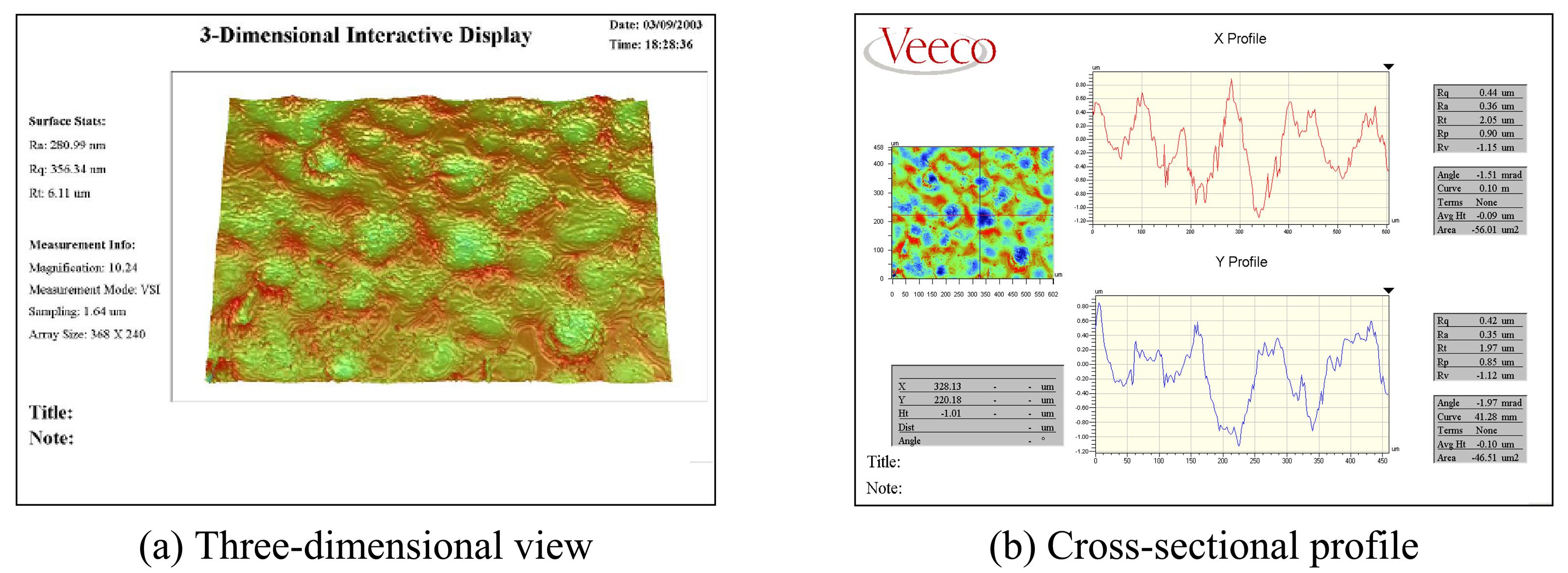
In this study, the matte finished surface shapes are investigated under various blasting parameters to obtain the optimum conditions. Figure 6 shows one of the best matte finished surface shape and the cross-sectional X and Y profile. Uniformly distributed waviness on the mold surface can be observed.
5.2 Performance analysis of the LGP injected by a matte finished mold
The effectiveness of the matte finishing can be investigated from the optical characteristics of the injected LGP using the mold fabricated via the powder blasting under the optimized process conditions. Twenty five positions for measuring brightness are sampled as shown in Figure 7. Figure 8 shows variations brightness measured at 25 points versus 5 powder blasting conditions and 1 controlled injection condition. The average brightness values of the sampled 25 points for 5 different blasting conditions are 1,900-2,000cd/m2. Final average brightness after optimizing injection parameters is 2,053cd/m2. From Figure 7 and Figure 8, it can be seen that the closer the distance between the CCFL and measuring points becomes, the higher brightness becomes. These results should be improved in order to obtain more uniformly distributed brightness for entire surface.
Variations of brightness versus three different blasting pressures are shown in Figure 9. Uniform brightness distribution can be obtained at 0.1MPa blasting pressure. At 0.15MPa blasting pressure, the closer the distance between the CCFL and measuring points becomes, the higher brightness becomes. At 0.05MPa blasting pressure, on the other hand, this trend is reversed. This phenomenon can be applied to obtain higher uniformity and higher brightness by varying the blasting pressure according to the target point locations on the LGP mold.
Actually, the cross-sectional profile or surface roughness of matted surface is not uniform all over the LGP surface as the dot size and its density varies from place to place. Therefore, shape shown in Figure 6 is one of the typical matte pattern. As shown in Figure 8 and Figure 9, brightness distribution is not uniform over twenty five measuring points, thus depth and period of waviness of matt pattern at the location of lower brightness should be adjusted by varying the blasting conditions. Matte pattern distribution with the specifications of brightness and uniformity of emitting light is the important know-how according to the LGP makers.
6. Conclusion
The following conclusions have been derived based on the present results.
- (1)
- A masking process for a LGP mold entailing laminating, exposure, and developing has been established.
- (2)
- LGP molds with micro pattern could be effectively machined by adopting a micro powder blasting technique, producing a prototype LGP successfully.
- (3)
- From the shape analysis and comparison of micro dot patterns on the injected LGP with those on the developed injection mold, good transcription of micro patterns was observed.
- (4)
- Matte finishing was successfully applied to the mold surface to improve the diffusion characteristics and brightness of the emitting light from LGPs.
- (5)
- From the results of this study, it can be concluded that the proposed method can be implemented successfully to form micro patterns on a LGP and thereby replace existing screen printing method.
References
- Slikkerveer, P. J.; Bouten, P. C. P.; de Haas, F. C. M. High quality mechanical etching of brittle materials by powder blasting. Sensors and actuators A: Physical 2000, 85, 296–303. [Google Scholar]
- Wensink, H.; Berenschot, J. W.; Jansen, H. V.; Elwenspoek, M. C. High resolution powder blast micromaching. Proceedings IEEE Thirteenth Annual International Conference on Micro Electro Mechanical Systems 2000, 769–774. [Google Scholar]
- Ligthart, H. J.; Slikkerveer, P. J. Glass and glass machining in Zeus panels. Philips journal of research 1996, 50, 475–499. [Google Scholar]
- Izawa, M. The trend and application of the abrasive jet machining. Journal of the Society of Grinding Engineers 2000, 44(1), 11–14. [Google Scholar]
- Solignac, D.; Sayah, A.; Constantin, S.; Freitag, R.; Gijs, M. A. M. Powder blasting for the realisa-tion of microchips for bio-analytic applications. Sensors and actuators A: Physical 2001, 86, 1–6. [Google Scholar]
- Kim, K. H.; Park, D. S. Effect of impact angle on the erosion of glass in powder blasting. Proceedings of Asia-Pacific Forum on Precision Surface Finishing Technology Nov. 21-23 Singapore 2001, 175–184. [Google Scholar]
- Park, D. S.; Cho, M. W.; Lee, H.; Cho, W. S. Micro-grooving of glass using micro-abrasive jet machining. Journal of materials processing technology 2004, 146(2), 234–240. [Google Scholar]
- Park, D. S.; Cho, M. W.; Lee, H. Effects of the impact angle variations on the erosion rate of glass in powder blasting process. International journal of advanced manufacturing technology 2004, 23, 444–450. [Google Scholar]
- Cho, M. W.; Kim, D. W.; Lee, E. S.; Cho, W. S.; Lee, J.; Park, D. S.; Seo, T. I. Machinability evaluation of Si3N4-hBN composites for micro pattern making processes. Key Engineering Materials 2004, 264-268, 869–872. [Google Scholar]
Figure 1.
Basic components of a BLU
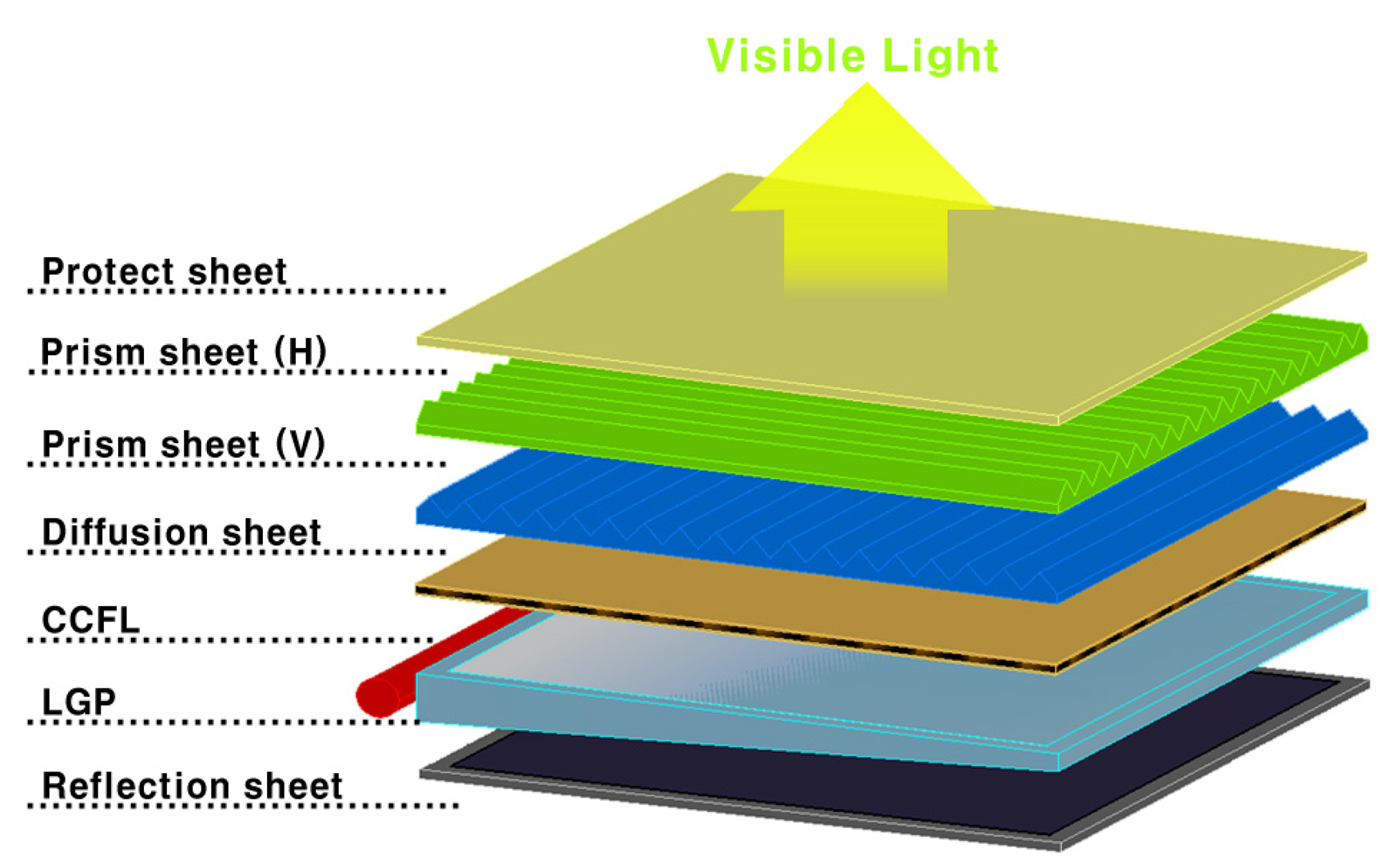
Figure 2.
Overall fabrication process for a LGP mold
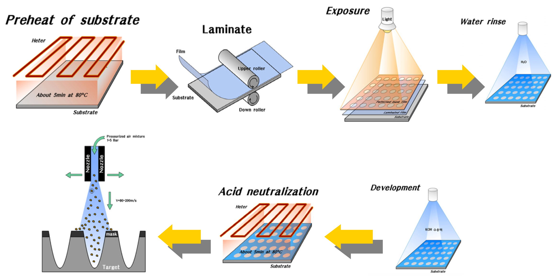
Figure 3.
Photographs of masked pattern shapes for powder blasting
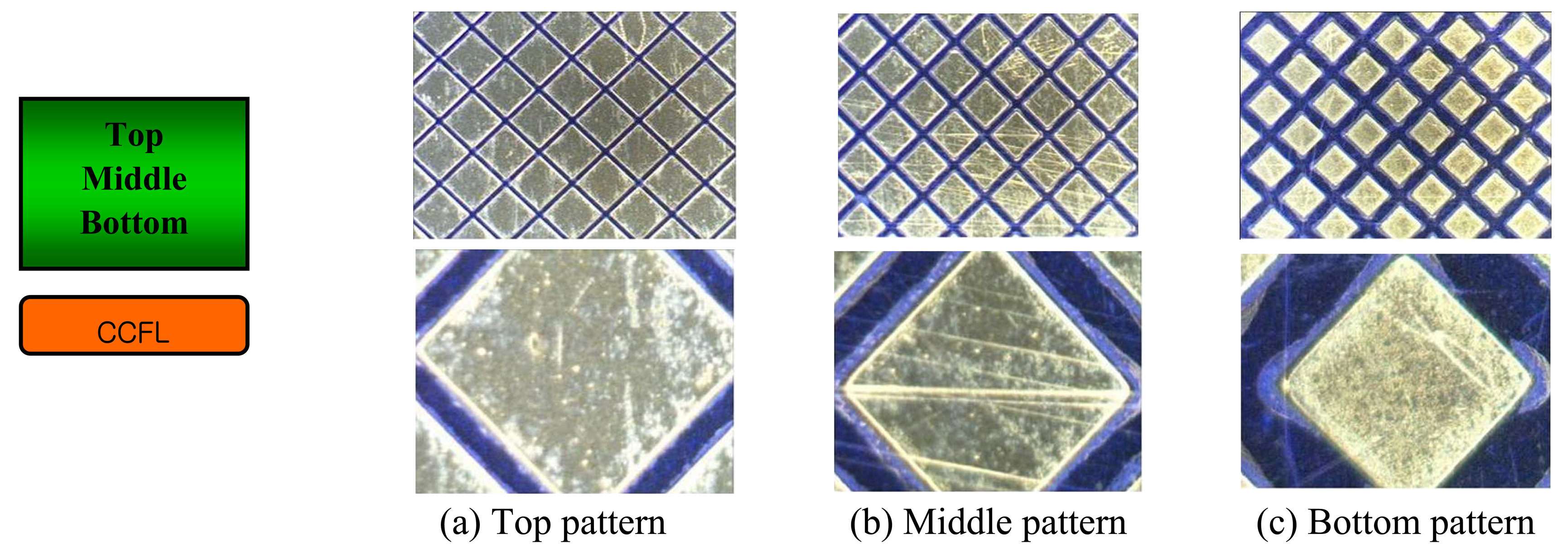
Figure 4.
A square type dot pattern formed on the powder blasted mold
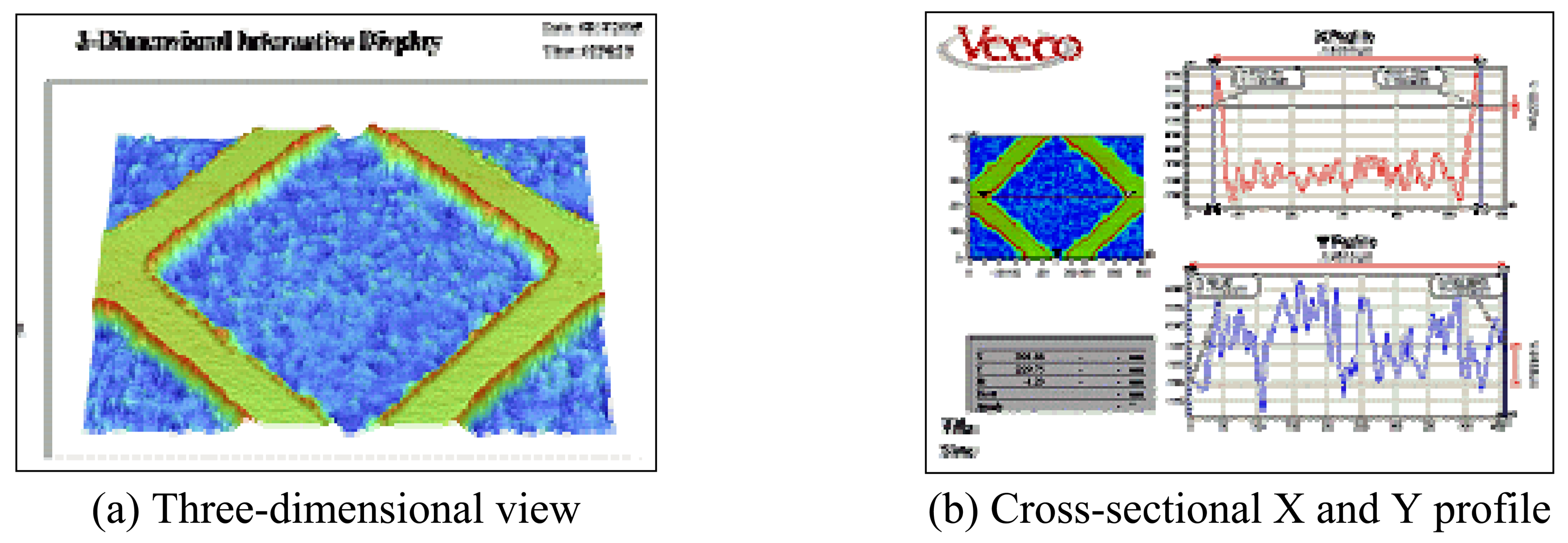
Figure 5.
A square type dot pattern formed on the test injected LGP

Figure 6.
Matte finish on the LGP mold surfaces

Figure 7.
Sampled 25 positions for measuring the brightness of display
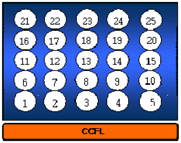
Figure 8.
Variations of the brightness of the developed LGP versus five blasting conditions and one controlled injection condition
Figure 8.
Variations of the brightness of the developed LGP versus five blasting conditions and one controlled injection condition
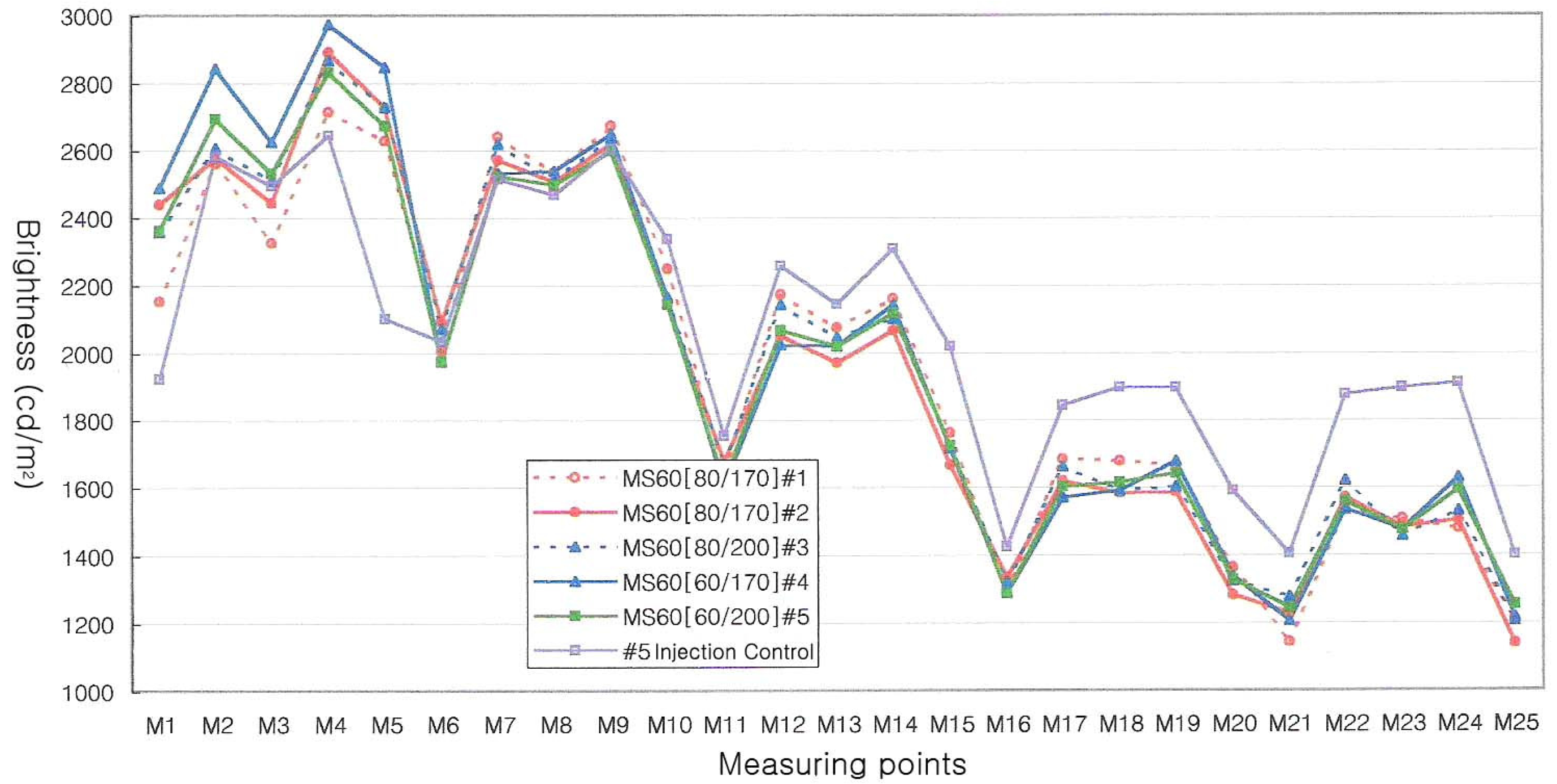
Figure 9.
Variations of the brightness of the developed LGP versus blasting pressures


| Abrasive(powder) | WA #800 |
| Blasting pressure | 0.25MPa |
| Mass flow rate of abrasive | 80-150g/min |
| Impact angle of abrasive | 90° |
| X-directional feed of table | 50mm/sec |
| Y-directional feed of table | 100mm/sec |
| Standoff distance | 100mm |
© 2008 by MDPI Reproduction is permitted for noncommercial purposes.
Share and Cite
MDPI and ACS Style
Jang, H.S.; Cho, M.W.; Park, D.S. Micro Dot Patterning on the Light Guide Panel Using Powder Blasting. Sensors 2008, 8, 877-885. https://doi.org/10.3390/s8020877
AMA Style
Jang HS, Cho MW, Park DS. Micro Dot Patterning on the Light Guide Panel Using Powder Blasting. Sensors. 2008; 8(2):877-885. https://doi.org/10.3390/s8020877
Chicago/Turabian StyleJang, Ho Su, Myeong Woo Cho, and Dong Sam Park. 2008. "Micro Dot Patterning on the Light Guide Panel Using Powder Blasting" Sensors 8, no. 2: 877-885. https://doi.org/10.3390/s8020877