1. Introduction
The triangulation method is a well-established approach in distance measurement. Triangulation method-based optical range finders usually use a light spot as a reference for distance measurement. The centroid of the light spot on the sensor can be converted into pixel coordinates that are almost hyperbolically related to the distance to be measured. Generally, the accuracy of the light sensor affects the performance of range finders significantly. The available sensors include human eyes, linear array position sensing detector, charge coupled device (CCD), and CMOS image sensor. The measurement range or resolution of optical triangulation measurement system depends on the geometrical structure of the system layout. The measurement range covered can be from a few centimeters to several meters, and the resolution achieved can be less than 1 μm.
In the past, most image vision systems adopted in the measurement field required complicated image processing techniques. Subsequently, a combination of vision systems and triangulation methods was widely used in many industrial applications [
1-
2]. Applications of the CCD imager were proposed in many fields, including the triangulation measurement, character recognition, optical tracking, on-line inspection, etc.
The study and development of CMOS image sensors has been a prevalent topic in the related research areas since the early 1990s. Recently, CMOS image sensors became popular devices and have been studied intensively. With the advancement of integrated circuit (IC) technology, all the necessary parts: CMOS image sensor, microprocessors, logic circuits, application-specific integrated circuits (ASIC) and memory components, can be implemented on one chip. The ultimate goal for the realization of a “system on a chip” (SOC) is to achieve high capability applications while remaining competitive in performance compared with CCDs. The CMOS image sensor is more miniaturized, lower cost (due to its manufacture process), and displays lower power dissipation than CCD image systems, and therefore it has gradually become a suitable choice in many applications.
In the early stages, the most prevalent applications of the CMOS image sensor perhaps were PC cameras, digital still cameras (DSC) or toy cameras. Recently CMOS image sensors were designed for mobile phones and Personal Digital Assistants (PDAs). The CMOS image sensor techniques have advanced rapidly, and the price of low-level CMOS image sensors is getting lower. Utilizing CMOS image sensors to replace array detectors and CCDs can simplify the signal processing procedures and reduce the auxiliary electronic components of the measurement systems. Especially, the image data can be selected by addressing the CMOS image sensors so that the processed data can be reduced significantly. As the manufacturing technology of the CMOS image sensors [
3-
4] has now advanced sufficiently to provide good stability and to achieve low cost, such sensors serve as alternatives of CCD sensors and have become significant in many optical applications. For example, the total price for lab fabrication of the proposed laser range finder (including CMOS sensor, light emitting diodes (LEDs), 904 nm laser diode, and the thermoelectric cooler) is about 120-150$, depending on the performance of the individual purchased components. From various aspects, it is clearly seen that CMOS image sensors would also be a good choice in industrial and automotive applications. The control of CMOS image sensors can be programmed via a standard inter-integrated circuit (I
2C) interface. The programmable features include the control for electronic exposure time (ET), the capturing for continuous or single frame image, and the operation modes of progressive or interlace scanning. The ET control is very important for the performance experiments of our designed ranger finders in industrial and automotive applications. The details will be described later.
The purpose of this paper is to present two kinds of low cost CMOS image sensor-based range finders (active and passive). Based on the triangulation method, the designed active/passive range finders are applied to the industrial and automotive fields. An extensive series of performance experiments are conducted and the main factors affecting their accuracy in distance measurement are also discussed in this paper.
2. Measurement Principles
2.1. Spot light location using the centroid method
The centroid method has been widely used to locate light spots on the image sensor. The centroid method can achieve sub-pixel accuracy in various types of image featuring applications, such as one spot or one stripe [
5]. The performance of the centroid method for range finders, 3-D measurements, target tracking [
6], star trackers [
7], etc., has been investigated thoroughly. If many targets exist simultaneously on a sensor, the computer can only treat some of targets in real time, even when equipped with a dedicated program. This is because the required algorithms can be very complicated so the speed of computer is severely reduced. For optical triangulation, the only output acquired from the image sensor is the centroid of the light spot, i.e. only a small area of the captured image is of interest. For this reason, there is a great demand for the image sensors that can provide high speed region of interest readouts [
8].
The process to sample image of a light spot was discussed in Fillard's work [
9]. By introducing sub-pixel processing techniques, the resolution of range finders can be increased. CMOS image sensors have been proven to meet the mentioned requirement [
10], so CMOS image sensors were adopted in this work to develop active/passive range finders. As for the light source, a laser diode (LD) and two infrared light emitting diodes (IR LEDs) were used in the designed active range finder and passive range finder, respectively. For locating the laser spot center in the triangulation-based active range measurement system, the one-dimensional centroid method was adopted. We also applied the two-dimensional centroid method to locate two light spots center in passive range finder.
The intensity profile
g(
x) of a light spot in one dimension (
x-axis) resulted from the convolution of the object (light spot) and the point spread function (PSF) of the camera lens. For simplicity, the proposed system focused on the one-dimensional case and assumed that there was no ambient lighting. The latter condition can be achieved by using optical filter(s), adjusting the gain control, and limiting the sampling area. These topics will be described and discussed later. Assume that the intensity of the
i-th pixel in a row of pixels of an image sensor is
gi. By setting threshold level, if a pixel that its intensity is less than the threshold level, then the pixel could be neglected. The calculated spot center
X̄c is considered as the centroid of
gi between pixels
m and
n, which is given by [
6]
As it will be shown in Section 5.1, subpixel accuracy can be easily achieved by calculating the centroid of a spot on the CMOS image sensor. A new range finder consists of one camera and a laser pointer attached with three LEDs was proposed by Takatsuka
et al.[
11], but their algorithms were too complicated for real time processing. To meet the requirement of real time operation, the algorithms used should be very simple. As described in Section 3.3, the new developed algorithms assure that the data quantity of captured image can be reduced significantly such that the image data can be processed by a computer or a digital signal processing (DSP) chip in a real time manner and thus our range finders can be applied to visual guidance or distance measurement in real time.
2.2. Active range finder
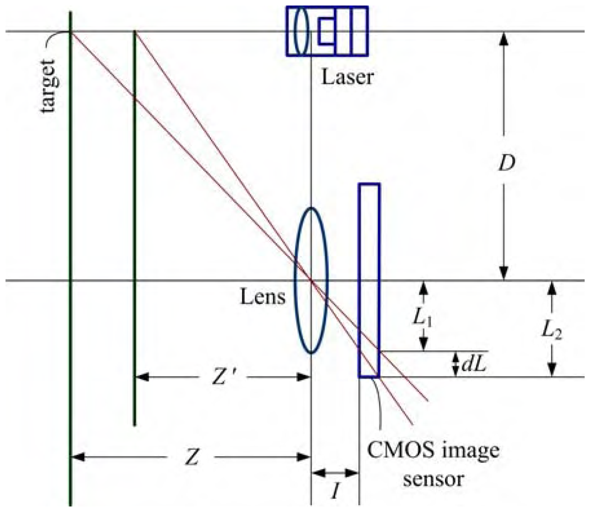
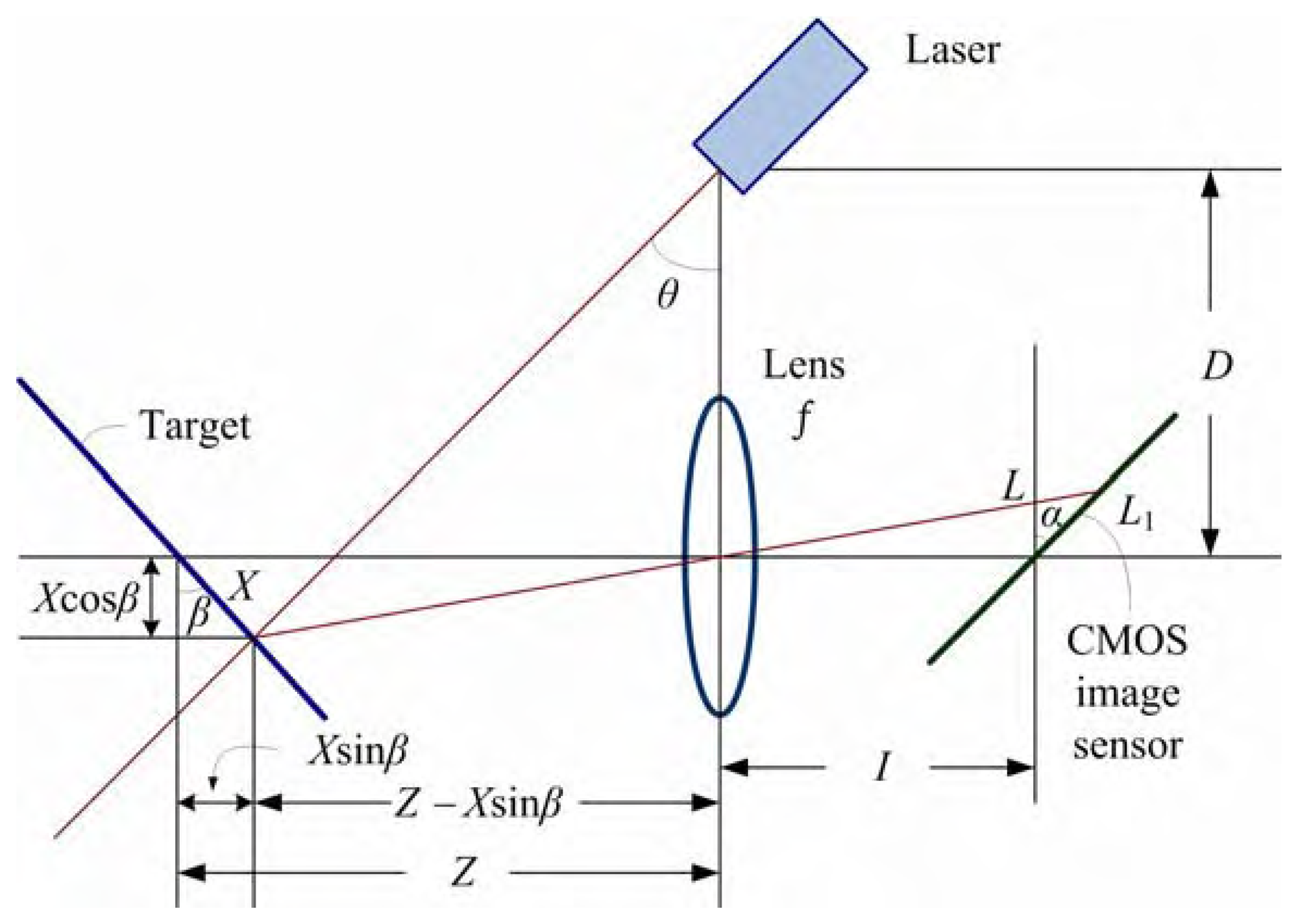
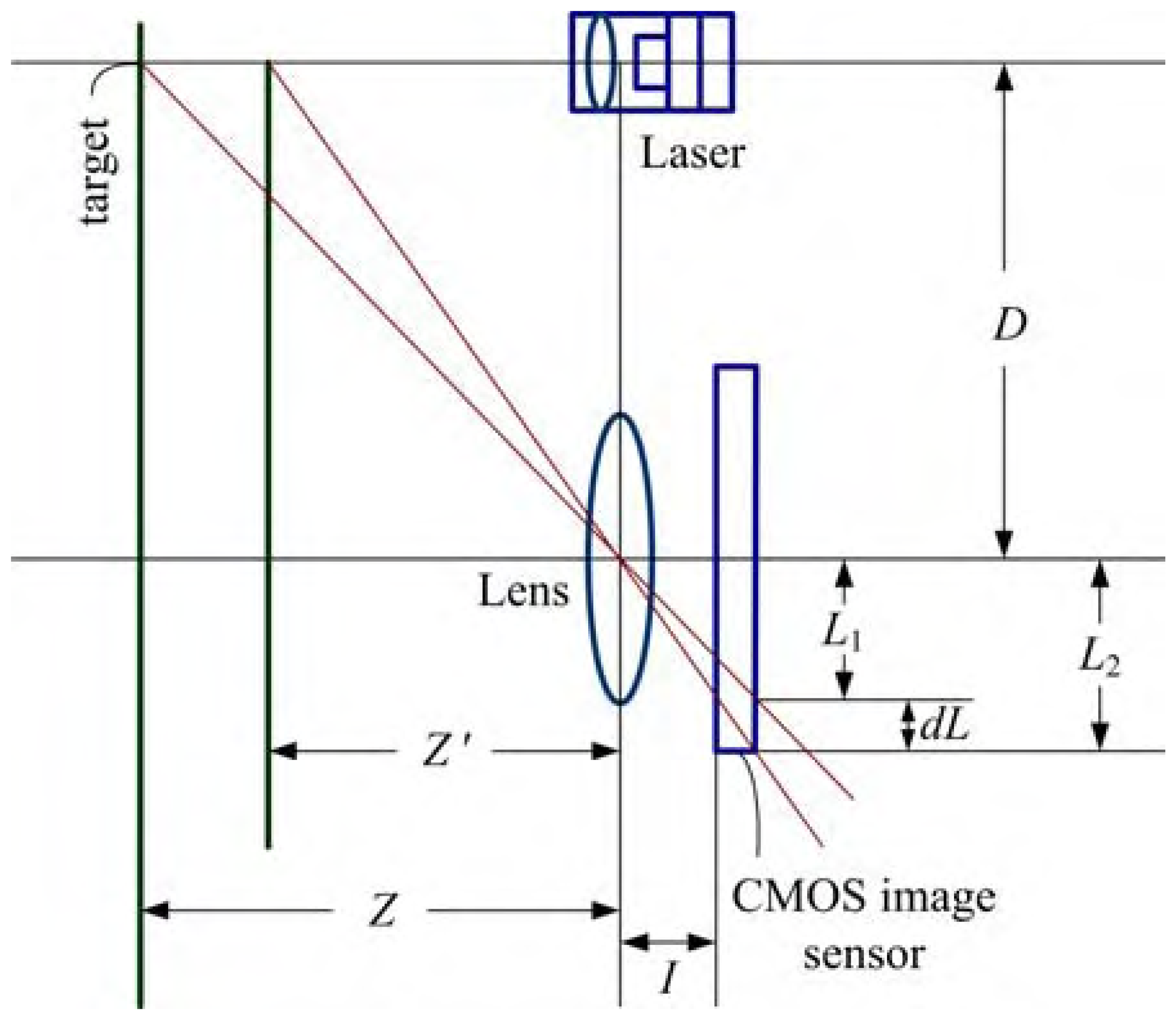
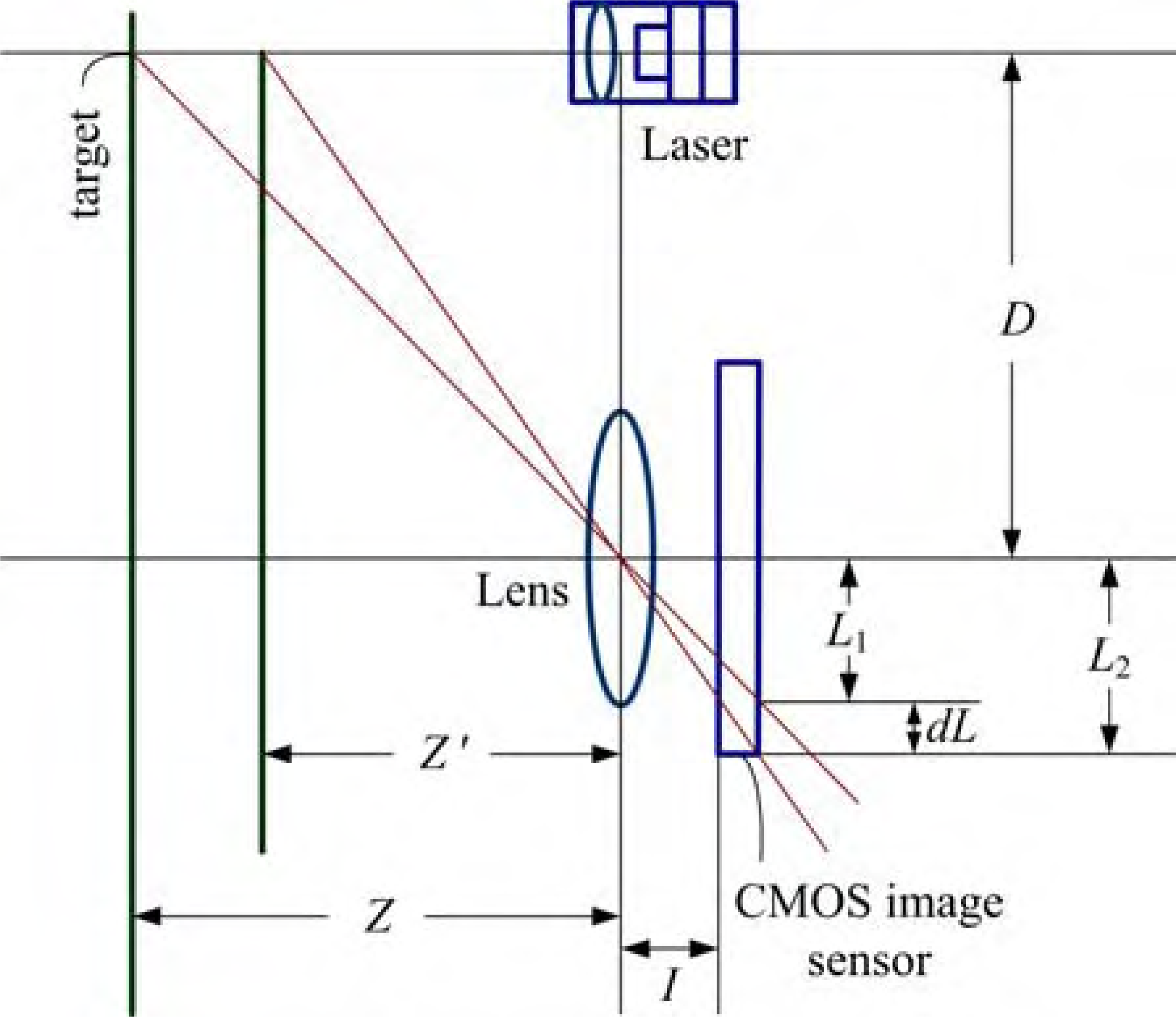
The operation principle of an active range finder is quite simple but strict. A laser diode providing a high spatial resolution is a good choice for designing active range finder. The laser diode adopted in the active range finder emits laser beam to illuminate the target, and then the distance can be determined by processing the reflected or scattered light. In addition to absolute distance measurement, traditionally the laser range finding devices are also used for 3-D vision, dimensional control, and positioning/level control. To evaluate the performance of the proposed active range finder, the experimental layout of the range finder system is designed and shown in
Figure 1.
Based on trigonometry, the generalized distance formula of this system is derived as below:
where
Z is the distance between the target and the lens,
L1 is the distance between the spot and optical axis on the sensor,
α and
β are the tilt angles of the sensor and target respectively,
X is the distance between the spot and optical axis on the target,
I is the image distance and is almost equal to focal length
f of the lens,
D is the distance between the laser and optical axis of lens, and
θ is the angle between the vertical and optical axis of laser.
When
α and
β are almost equal to zero, then
Eq. (2) can be simplified to
Differentiating
Eq. (3) with respect to the measured distance and rearranging the result yields
where
dZ is the resolution of the designed active range finder. From
Eq. (4), it is clearly seen that the resolution of the system can be increased by using a longer focal length
f for the lens, enlarging the distance
D between the laser and the CMOS image sensor, and using sensors with smaller pixel size
dL. The designed active range finder belongs to an in-door use device. For industrial applications, the effective measurement distance of the proposed range finder is within the range of 1 to 8 m. The distance measurement in automotive field is another feasible application of the designed range finder, which will be presented in detail in Section 6.
2.3. Passive range finder
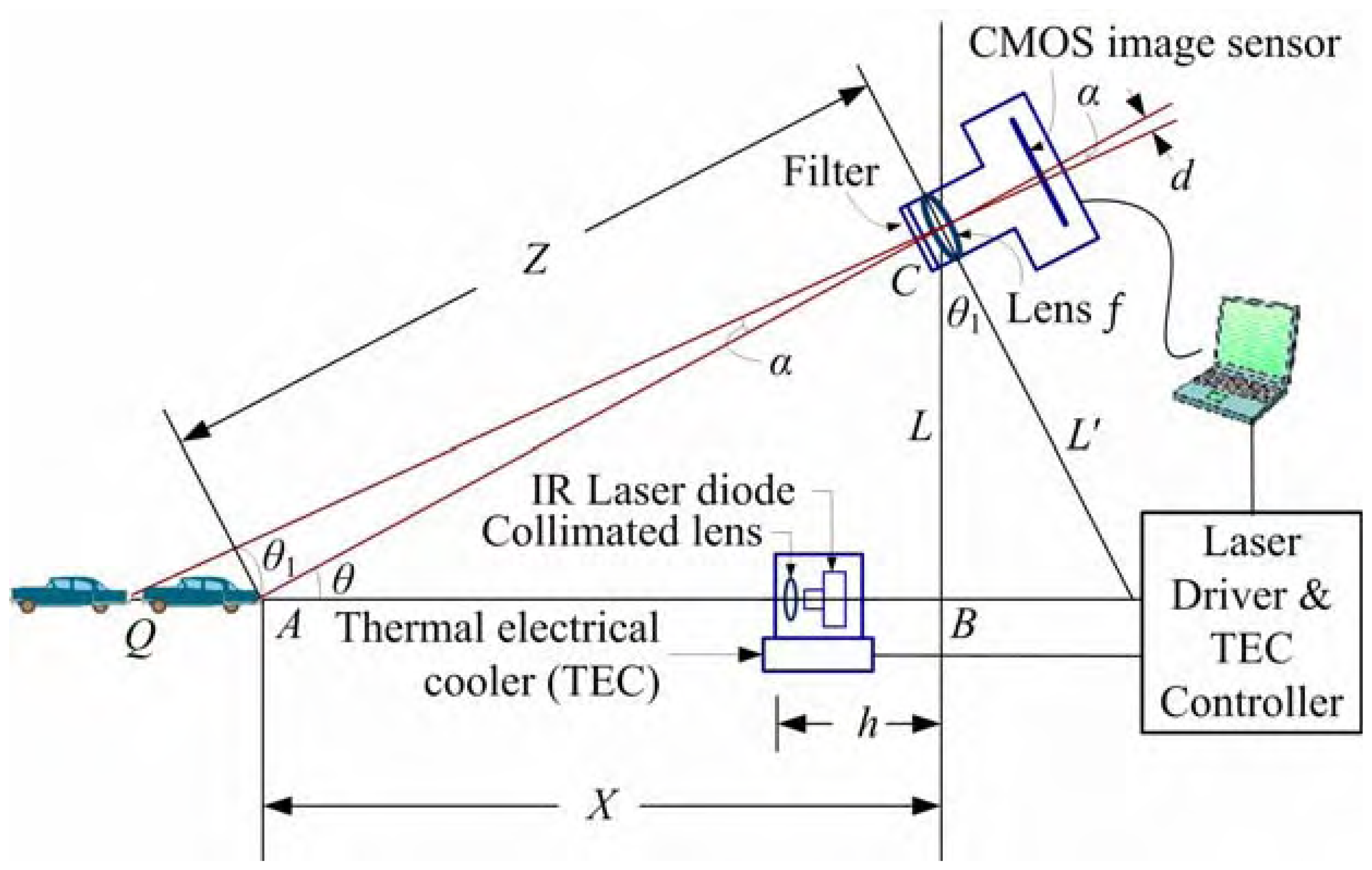
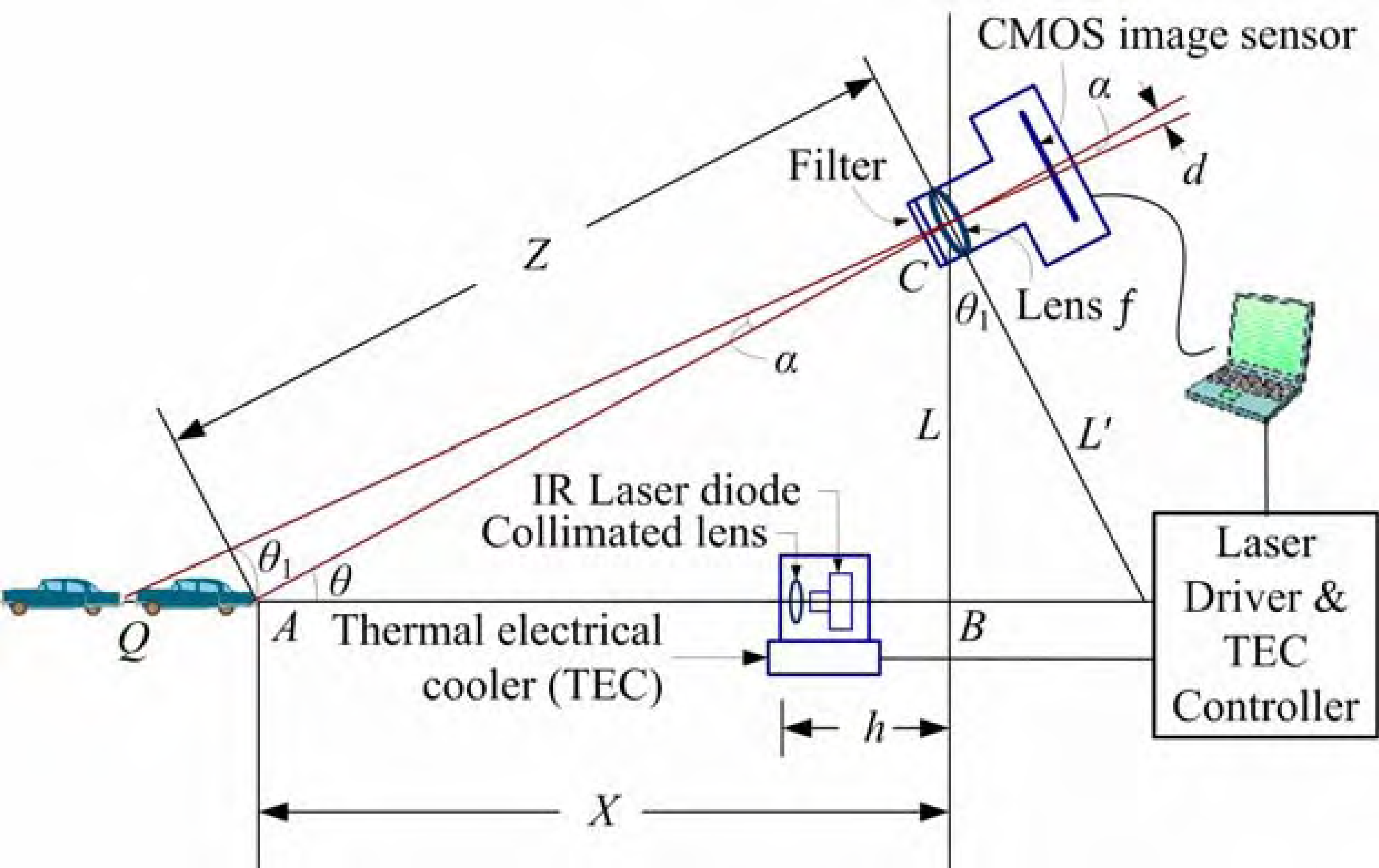
In this work, we also developed a novel passive range finder. The designed passive range finder is based on the triangulation method, but two light sources are installed on the object to be measured. The two light sources used are IR LEDs, which belongs to the indoor device class. The other light sources of passive range finder are the taillights of its preceding vehicle, and their spectrum might cover from red to infrared wavelengths [
10]. Since the designed passive range finder can sense both two taillights of preceding vehicle, it also refers to double targets tracking (DTT) system. The system layout of the designed passive range finder is shown in
Figure 2.
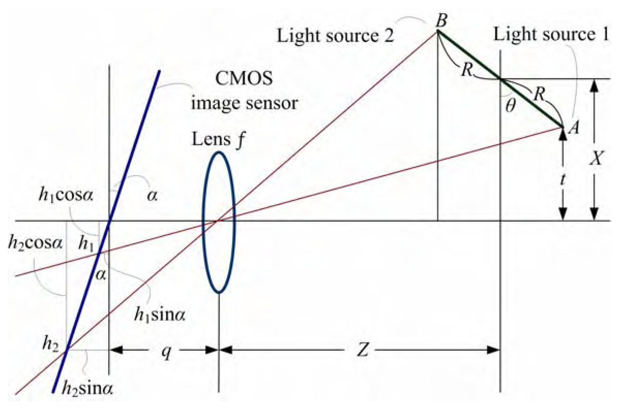
The generalized formula for passive range finder is expressed as
and
where
Z is the distance between the target and the lens,
h1 is the distance between the spot and optical axis on the sensor for the first light source, and
h2 is the distance between the spot and optical axis on the sensor for the second light source.
α and
θ are the tilt angles of the sensor and target respectively,
t is the distance between the first light source and optical axis on the target.
q is the image distance and is almost equal to focal length
f of the lens,
h1 and
h2 are the distances between the spot and optical axis on the sensor for the first light source and the second light source, respectively,
R is the half length of the target.
When
α and
θ are almost equal to zero,
Eq. (5) becomes
where
Y =
h2−
h1 is the distance between the two spots on the CMOS image sensor.
Differentiating
Eq. (9) with respect to parameter
Y gives
where
dZ is the resolution of the designed passive range finder. From
Eq. (10), the resolution of the passive range finder system can be increased by using a longer focal length for the lens and increasing the distance between the two light sources, just like as two LEDs or two lasers emit parallel beams.
To increase the signal-to-noise ratio (SNR) of the range finder system, a narrow band pass filter (NBPF) was mounted in front of the CMOS image sensor to reduce undesired light. On the other hand, the automatic gain control for the exposure time (ET) of the CMOS image sensor is similar to the variable neutral density filter, which can either be adjusted by the user or by a control program. The ET value of the CMOS image sensor can be adjusted to different levels for different situations. This means that the SNR can be improved by setting the gain level. By decreasing the gain level, i.e., decreasing the ET value of CMOS image sensor, the gray level of spot that appears in the captured image frame will be unsaturated except for the light spot(s) with high intensity. Setting a suitable threshold above the lowest gray level of the captured image, the center position in the image can be found out. Finally, to decrease the data quantity in an image that the computer has to process, and to reduce the backlight noise, this work used zone selection approach to pick over the required image data. The data in a specific zone can be extracted by a computer program, thus the amount of image data can be reduced significantly. The related flowchart of ET control program will be described in Section 3.3. This manner acts like a spatial filter, which is similar to add a slit in front of the CMOS image sensor.
3. Hardware and Software Design of Active/Passive Range Finders
3.1. Active range finder for short distance measurement
In this work, a simple active range finder system is designed for measurement of short distances ranging from 1 to 8 m. The designed system can be applied in automated factories for online thickness measurement, controlling moving machines or automobiles indoors. For simplicity, the angle
θ in
Figure 1 is set to be 90°. Therefore,
Figure 1 can be simplified to
Figure 3.
The specifications of the components used in the active range finder are described below. The CMOS image sensor (model no.: HV7131D, Hynix Semiconductor, Inc.) used in the system provides an active area of 5.3 × 3.8 mm2. Due to its high accuracy and stability, the CMOS image sensor was used to detect the laser light spot along one axis or two light spots. The HV7131D sensor can provide continuous position sensitivity with resolution of 8 μm over a wide dynamic range. Also, the ET range of the CMOS image sensor can be adjusted from 0 to 99 (i.e., corresponding to 1/15 to 1/3 s/frame). The operational wavelength of the adopted laser diode (model no.: QL63d5sA, Moretec, Inc.) is 650 nm and its rated output power is 3 mW. The full width at half maximum (FWHM) of the adopted NBPF (model no.: BP650, Unice E-O Services, Inc.) is 11 nm, and its central wavelength is 650 nm.
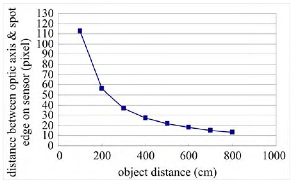
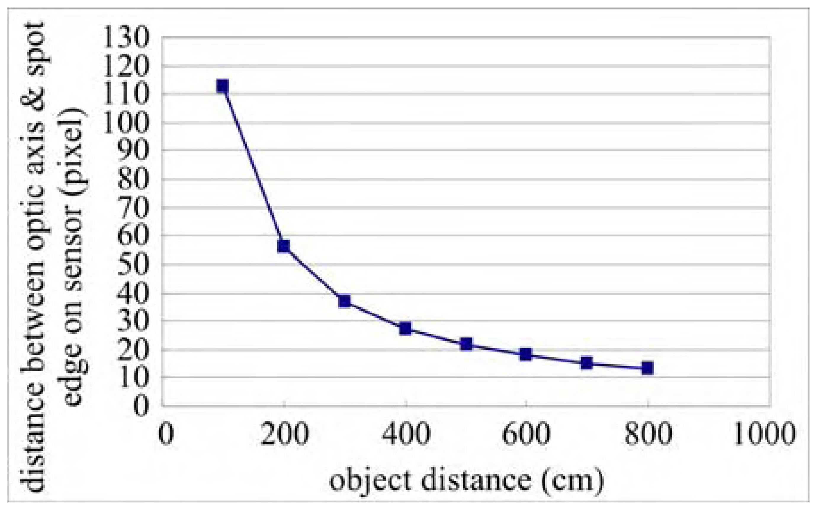
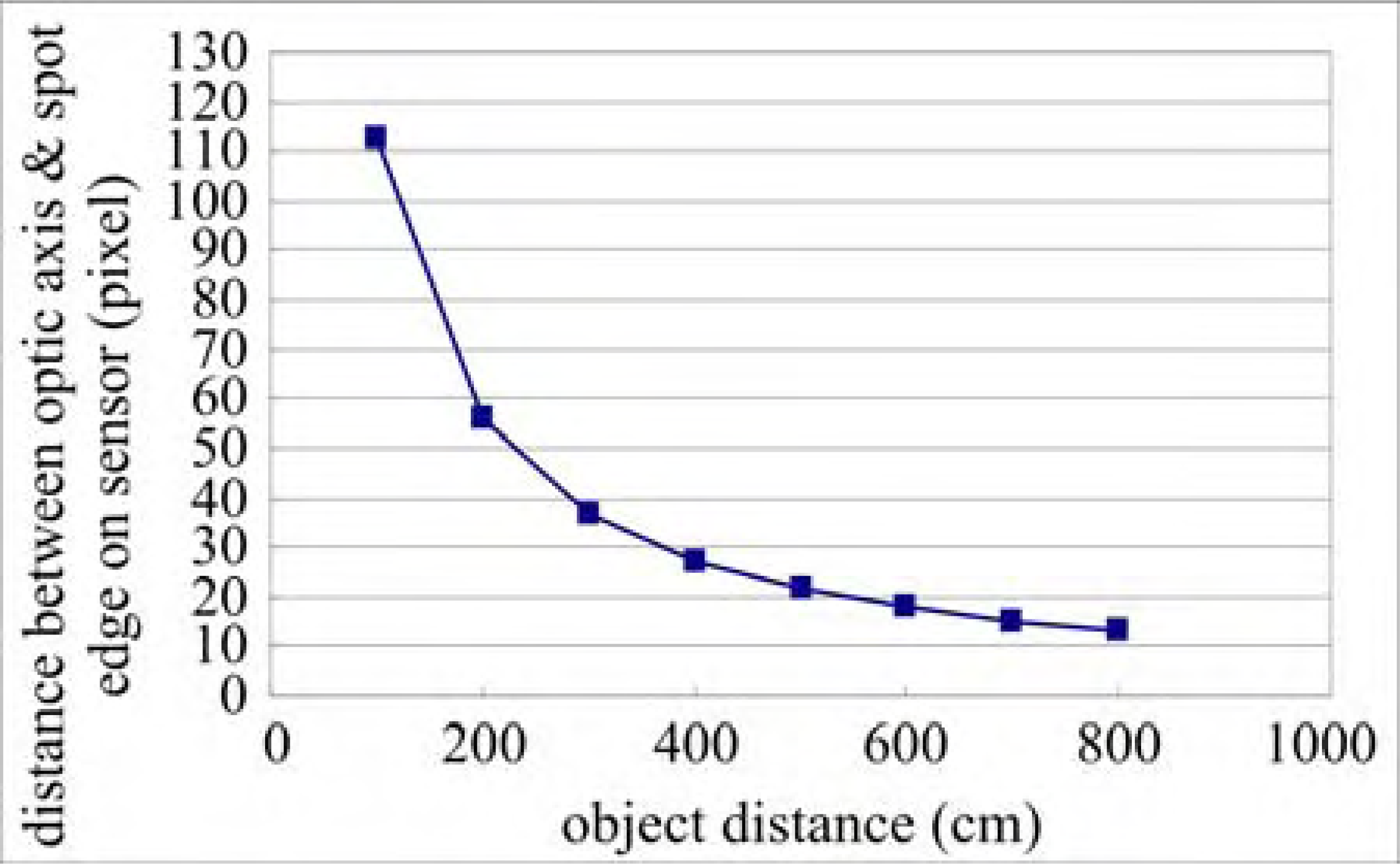
For the active range finder, the measured distance versus the distance between the optic axis and spot (
dL) is not linear. From our experiments, the relationship between distance and pixel coordinate exhibits hyperbolically, as shown in
Figure 4. For this reason, the active range finder needs to be calibrated. Point-to-point calibration was adopted for this work since it will provide the best accuracy. The accuracy of curve fitting depends on how many calibration points are adopted. The concept can also be applied to outdoor use, for example, the distance measurement for a preceding vehicle described in Section 6.
3.3. Software design
In this work, we have developed specific ET control programs for both of active and passive range finders, which are suitable for indoors outdoors applications, respectively. The software program, developed in VC++ language, was also utilized to perform a fast calculation of the centroid position so that the distance between range finder and object can be estimated. These programs were integrated and built into the designed range finder systems. To save space, only the program for the passive range finder is presented in this paper.
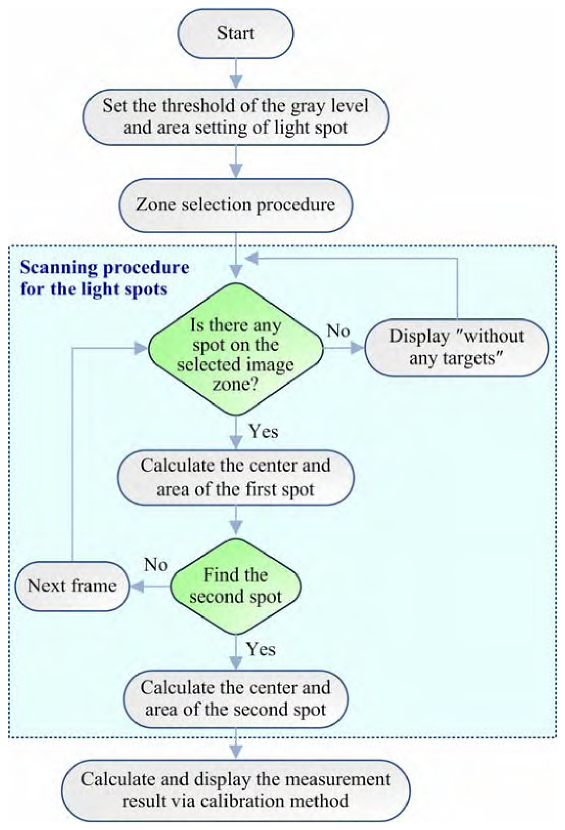
The signal processing flowchart of the passive range finder used in door is shown in
Figure 5. This program is chiefly used to estimate the distance between two similar spots in the consecutive frames. When the program is started, the gray level and area settings of the light spot to be detected are set first. Since the designed passive range finder used two IR LEDs (SFH484) driven by the same current, the intensities of both spots on the CMOS image sensor caused by the two IR LEDs should theoretically be the same. However, even now the object plane is perpendicular to optical axis (i.e., the tilt angles
α and
θ in
Fig. 2 are almost equal to zero for most of measurements), the spots' areas on the CMOS image sensor exhibit a slight difference. Therefore, the area settings for two spots should be also set to avoid capturing wrong light spots. According to the gray level setting, the captured image can be partitioned into several image zones. The light spot will be located in some specific image zones with gray level higher than the preset threshold. In Section 5.4, it will be clearly seen that when the intensity contours with gray level greater than 250 or less than 10, the contours of spots distribute randomly. Basically, the image zone with gray level less than the threshold can be regarded as background and can be neglected. So, only some portions of the entire captured image need to be processed. This procedure can reduce the computation burden significantly. After this step, the procedure for scanning spots based on zone selection method is initiated. The image zone with gray levels higher than the preset threshold needs to be examined if spot exits or not. The details for scanning the light spots are depicted in
Figure 5 (i.e., the middle portion enclosed by the dashed line). After each spot is found, the program calculates the center and area of the spot. Once the centers and areas of two spots in consecutive frames are obtained, the distance between the range finder and the object can be determined via the mentioned calibration method. With some modifications, the related programs of the active range finder are similar to the one mentioned above and are omitted here for saving space.
5. Error Analysis
It is well known that the speckle effect of lasers is the major factor of the systematic errors occurring in the active triangulation method and the uniformity of the measured surface is another factor. Possible sources of measurement deviation include shot noise, amplifier noise of the CMOS image sensor, non-uniform pixel response, and quantization error. The errors due to the noises from the CMOS image sensor are not considered here. In this work, we only consider the whole systematic error, including point spread function effect of the lens, effect of laser speckle (for active triangulation measurement), thresholding effect, degrees of blur, and sensitive area of sensor. In general, using wider sensitive area of sensor and increasing degrees of blur reduces systematical error. Taking the effects of the various systematic errors in different applications into consideration, the following evaluations were conducted.
5.1. Stability analysis of the CMOS image sensor
To evaluate the stability of the CMOS image sensor, the IR LED was chosen as the light source due to its operational stability. The test was conducted on an optical table. The distance between the LED and the CMOS image sensor is 200 cm, and the ET value of the CMOS image sensor is set to be 2 (approximately equals 0.072 s/frame). Every distance test was conducted 1000 measurements. When the LED only radiates optical power of 0.3 mW, the CMOS image sensor will not saturate, i.e., the gray level of the captured image is lower than 255 (highest grey level). However, the CMOS image sensor saturates when the LED radiates more than the optical power of 3 mW. In this case, the gray level of captured image reaches the highest level of 255.
The test results are summarized in
Table 3. It is evident from
Table 3 that the effect of light source stability becomes more significant when the LED emits larger power. This increases the one standard deviation of the distance measurements. However, the experimental results also demonstrate that the adopted CMOS image sensor still provides excellent stability and is a good choice for a position-sensing detector.
Table 3 shows that an average of the one standard deviation better than 0.0045 pixels in both measured directions can be achieved by the adopted CMOS image sensor even under LED is saturated. This fact implies that the CMOS image sensor is also a good choice for position-sensing detector. It is worthy to note that suitable power of light source will make the system more precise. Except for adjusting the power of light source itself, changing gain control, i.e., the ET value of the CMOS image sensor, can also achieves good system performance.
5.2. Comparison of the light sources
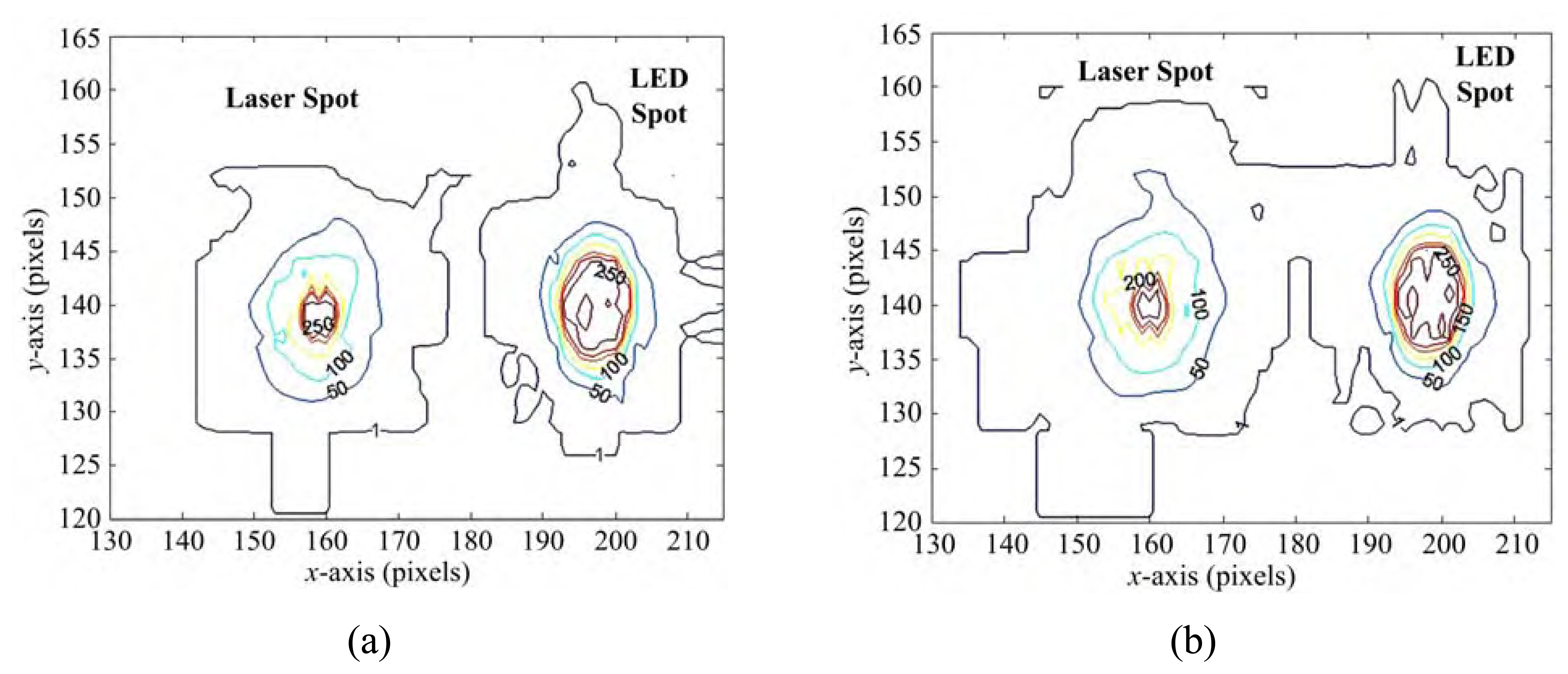
LED is an incoherent light source, but LD is a coherent light source. The latter one exhibits more severe influence on the precision of distance measurement due to its speckle effect. Basically, the resulted intensity contours on the CMOS sensor depends on the relationship between coherency time of the laser and exposure time of camera. An extensive series of tests were conducted and recorded at different time. For illustration, we measured the intensity contours of LED and LD at different time and the results are shown in
Figures 7(a) and 7(b), respectively. The left one is the intensity contour of LD, the right one is the intensity contour of LED. It is obviously from
Figure 7 that the shape of LD changed with different time more apparently. Inspecting the intensity contours of gray levels 50 and 100 in
Figures 7(a) and 7 (b), for example, the contour shapes of the laser spot vary more significant than those of LED. Due to larger intensity variation of the spot illuminated by LD, the error occurred in the measurement of the intensity contour of LD will be more significant than that of the LED.
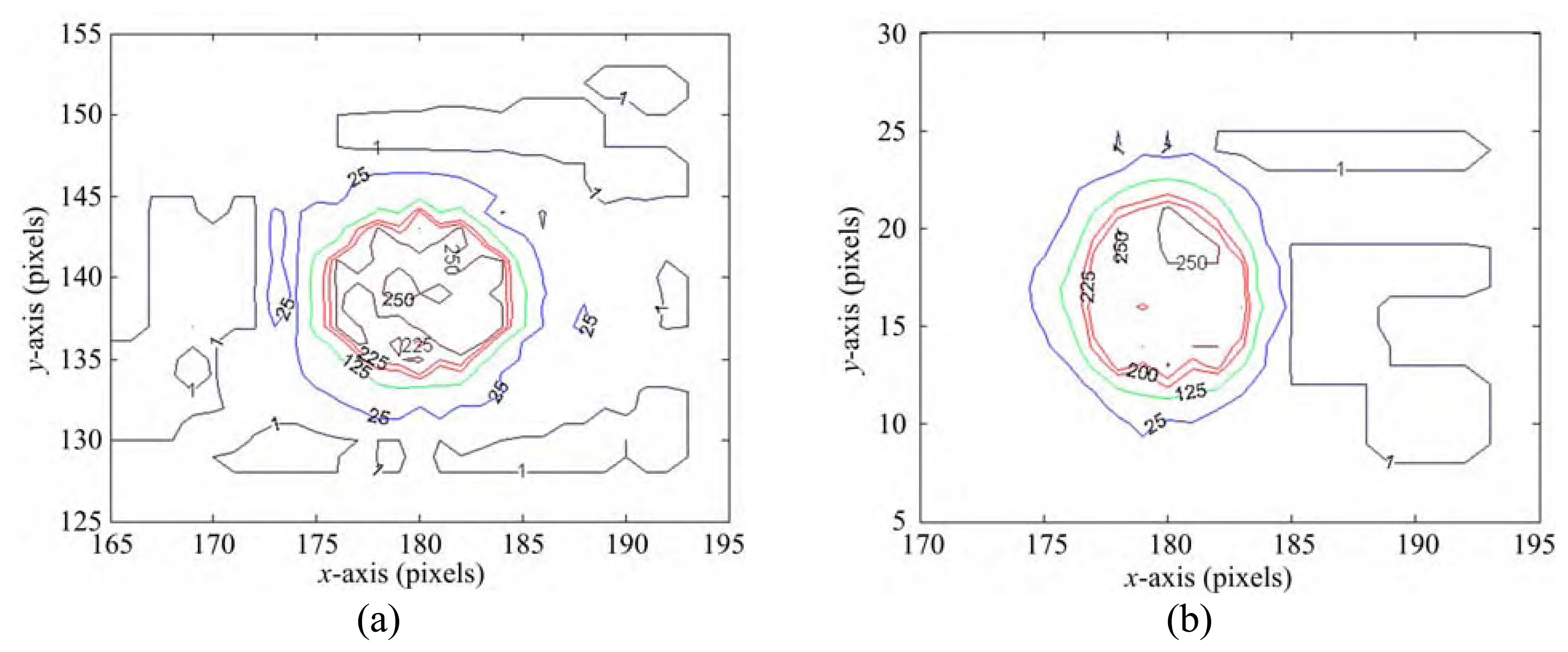
5.3. Optical aberration effect
Due to the aberration effect of the lens, the light spots on axis and off axis appeared respectively like a circle and an ellipse, as shown in
Figures 8(a) and 8(b). This effect could be eliminated by calibration. In this work, curve fitting experiments have been conducted carefully. The light spot near the optical axis will image on the CMOS image sensor with high fidelity, but the light spot far away from the optical axis exhibits more distortion caused by the aberration of the lens. In general, the calibration of the range finder systems can be conducted by curve fitting method. In this work, we calibrated the designed systems via a point by point fitting approach. The more calibration points taken, the more accurate the system will be. Besides, we also use specific gray level setting in the proposed signal processing algorithm. The right threshold can let the shape of intensity contour of spot be located in symmetrical area. The small and randomly distributed contours with asymmetrical shape will be regarded as fake spot caused by aberration effect and can be reduced via gray level threshold setting, as described in the next section. Using this approach, the error can be reduced to a pretty low value.
5.4. Effects of gray level threshold setting or gain control on CMOS image sensor
The different thresholds or gain settings apparently influence the centroid calculation, especially for unsymmetrical spot size [
10]. For increasing measurement accuracy, the light sources should be examined and tested in detail, no matter what LD or LED is used. It is worthy to point out that the laser beam should be symmetrical along the optical axis. Otherwise, a new error source may be introduced by changing the gain (or ET value) of the CMOS image sensor. The effect of different thresholds or gain settings on the centroid calculation, especially for unsymmetrical spot sizes, was investigated in detail in our previous work [
10].
In the pulse-based prototype system of our previous work [
10], the dominant wavelength of the laser diode was 905 nm, and was maintained by a thermal electrical cooler (TEC). To evaluate the effects of gray level threshold setting or gain control on CMOS image sensor, an extensive series tests were conducted on a highway at midday. To save space, only the experimental results on the effect of ET control are presented. During experiments, the signal of IR laser was stronger than the background noise. When the ET value of the CMOS image sensor was set at 20, the captured image is as shown in
Figure 9(a). The laser spot in the captured image can be easily discriminated by changing the ET value to 2, as shown in
Figure 9(b).
Figure 9 clearly demonstrates the effect of the ET control. By reducing the bandwidth of the NBPF and increasing the power of the laser, the S/N ratio achieved by the designed range finder can be pretty high. In order to decrease the time of calculation of the data (i.e., the whole pixels in a frame), it is worthy of note that only one linear array of pixels in the captured image was extracted via a VC++ based computer program.
5.5. Vibration effect
If there is relative vibration between laser and the CMOS image sensor, the uncertainty of the active range finder system would increase. Our previous work [
10] has shown that the relative vibration effect between the laser and the CMOS image sensor couldn't be ignored in a larger triangulation measurement layout. For most applications of the distance measurements in the automotive field, however, this effect can be omitted without losing system performance. For the details, the readers should consult our previous work [
10].
5.6. Angle effect
In the DTT system, the tilted angle of two light sources will affect the uncertainty of the range finder system, especially for in door use. For the application on highway, however, the effect of curved highway could be omitted. This issue will be described in detail in Section 6.
6. Applications
In the following sections, two applications of the designed active/passive range finders to distance measurement in automotive field are presented.
6.1. Active range finder in the automotive field
It is important to maintain a suitable distance from the preceding vehicle on the freeway. However, it is very difficult for a driver to judge the real distance by eyesight alone. In addition, adaptive cruise control (ACC) systems [
13-
14] for controlling or measuring the headway distance from the host vehicle to the preceding vehicle are too expensive for most drivers. Thus, a low cost prototype of active range finder using the CMOS image sensor in the automotive field was developed in this work.
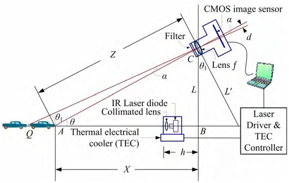
The designed active range finder system adopts a simple structure based on triangulation method. The geometrical layout of the system is shown in
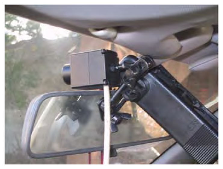
Figure 10, which consists of an IR laser diode (LD), a collimated lens, a filter, a collective lens with focal length of 16 mm, and a CMOS image sensor. In order to increase the S/N ratio of the system, a narrow band pass filter (NBPF) with central wavelength of 905 nm and FWHM of 1-2 nm was mounted in front of the CMOS image sensor to filter out the visible light. The IR LD with operational wavelength of 905 nm was set up on the bumper of the car, and the CMOS image sensor was mounted on the brace of rear mirror. The model number of IR laser diode adopted in the system is the LD-905 (Advanced Chips and Product Corporation, USA). In this application, the layout parameters of the designed active range finder system are
L = 800 mm and
f = 16 mm. The CMOS image sensor was mounted on the rear-view mirror brace, as illustrated in
Figure 11. And the experimental data were obtained by averaging 50 measurements.
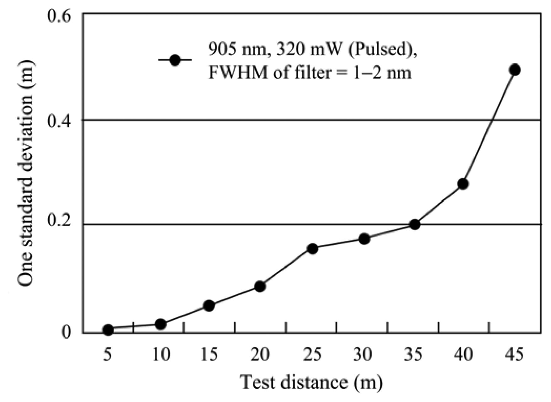
On a highway in Taiwan, the normal speed limit for a car is set around 90-110 km/h, and the distance between vehicles must be kept above 45 m. For this reason, the conducted test distances between two moving cars are chosen as 5–45 m. During experiments, the speed and distance of two tested cars were remained at suitable settings for safety. For every test distance, the measurements were conducted 50 times. The one standard deviation versus the test distance of the experiments is depicted in
Figure 12. From the experimental results shown in
Figure 12, it is found that the distance is estimated with accuracy better than 1.1% within the range of 5–45 m.
The proposed measurement scheme for active range finder can also be applied to blind guidance. The range finder can be integrated with a mobile phone. By reducing the distance between the IR laser and the CMOS image sensor to a suitable value, e.g., 10 cm, the blind user can use the combined system to automatically measure the distance to the object in front (1–3 m). Alternatively, people can use the range finder to get the scenery by adjusting the ET value and send them to the person who can guide the blind.
6.2. Tracking two taillights of a vehicle at night using a passive range finder
Usually, it is hard for drivers to estimate the distance between two moving cars, especially at night. To promote driving safety, an accurate distance measurement between two moving cars becomes an important issue in the automotive field. A two-beam laser triangulation for measuring the position of a moving object was proposed by Zeng
et al.[
15] We followed the scheme proposed by Zeng
et al. to develop our DTT system using CMOS sensor based passive range finder for vehicles.
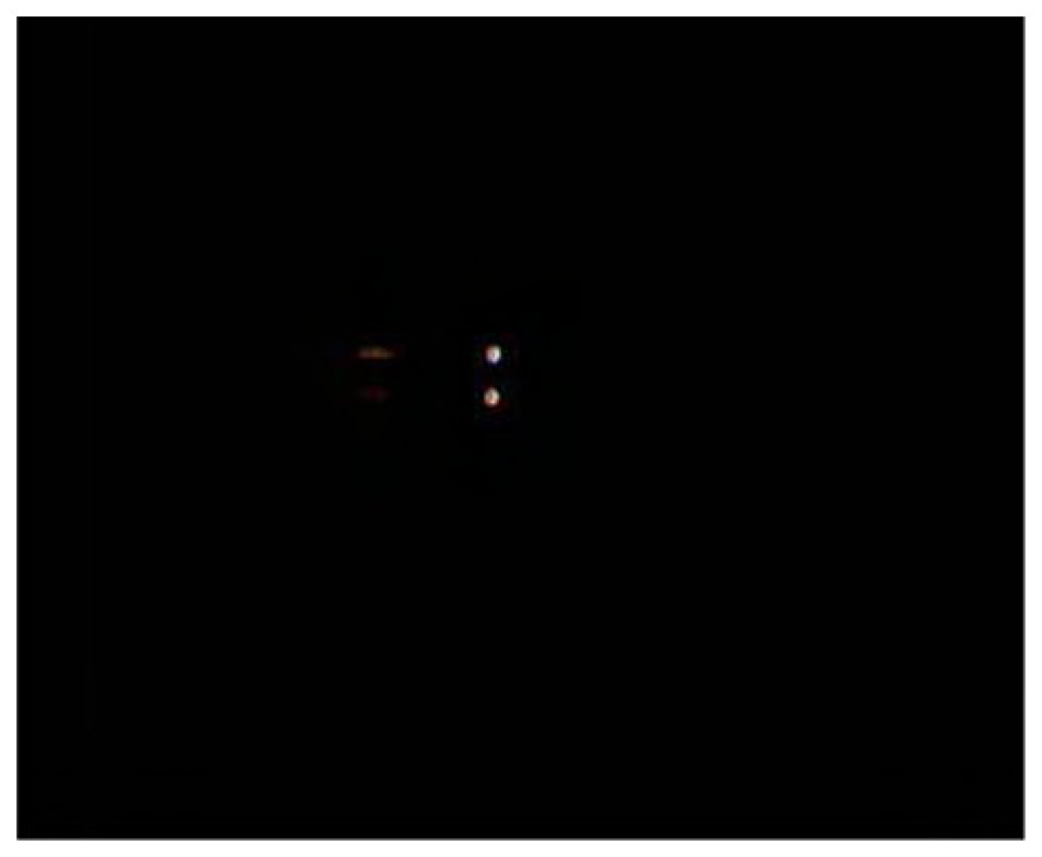
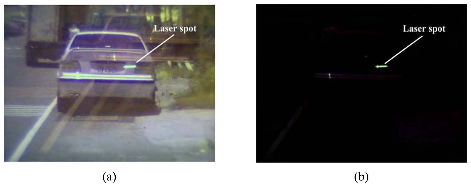
At night very often there are two taillights on the preceding vehicle. By tracking these two light signals, we can realize the real distance between two vehicles. The experimental setup for this application is similar to that of Section 6.1 and is omitted here to save space. By adjusting the gain control to the lowest level and setting the threshold level at half, the captured image can be simplified significantly. The effect of gain control on the captured image can be illustrated by
Figure 13. The captured image when gain level is set at normal level is shown in
Figure 13(a). But, when gain level is set at the lowest level (corresponding to ET = 2, i.e., approximately equal to 0.072 s/frame), the captured image become the one shown in
Figure 13(b). From the shown figures, it is clearly seen that the “background noise” can be significantly reduced by controlling the ET value. By selecting the zone area located between two white lines of a lane in the captured image, the distance of preceding vehicle in the same lane can be determined easily. The different filters used in these systems we developed should be chosen according to the real situation we met. For example, a narrow band pass filter has been adopted in the active laser range finder in the automotive field.
In this experiment, the image distance
q is approximately equal to the focal length (
f = 7.5 mm) of lens, and the distance between two backlights of vehicle under test is 120 cm. Performing measurements for every test distance between two moving cars 50 times, the one standard deviation of the experimental results is listed in
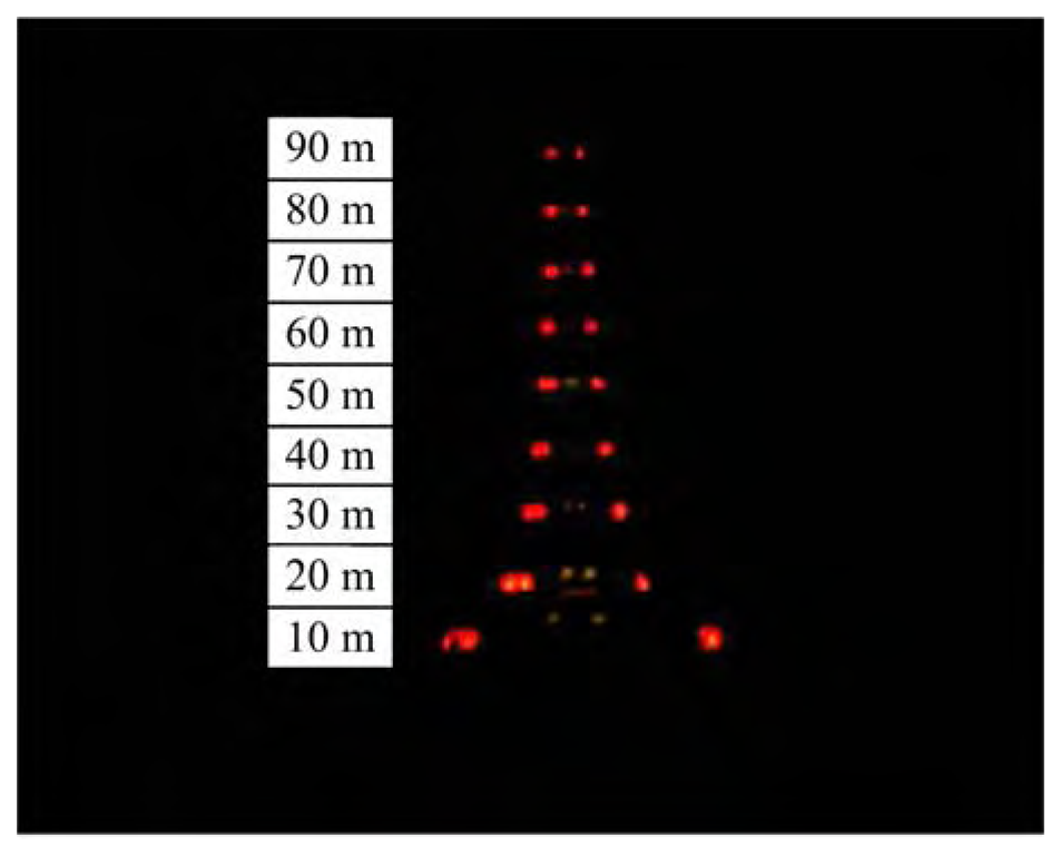
Table 4. From this table it is seen that when the test distance is set at 10 m, the designed DTT system provides one standard deviation of about 1.86 pixels. Translating this value into real distance gives the one standard deviation of 0.17 m. When the test distance is set at 20 m, the one standard deviation of the designed system is lowered to 0.11 pixels approximately. And this can be translated into a real distance of 0.04 m. Due to irregularity of one taillight of the test vehicle, as shown in
Figure 14, the one standard deviation for the test case of 10 m is larger than that of 20 m case.
Applying the proposed passive range finder to track two backlights of vehicles for automobile anti-collision at night could save the power consumption of laser radar. The designed system could also be integrated into ACC system. The distance 2
R between two taillights of preceding vehicle can be determined by using active range finder and
Eq. (9). The size of the taillights of the preceding target is variable depending on the measurement distances and different kinds of vehicles. From the DTT experimental results, it clearly demonstrates that the more accurate measurements provided by the range finder system will be achieved for a longer distance between two vehicles. In the near distance situation, on the other hand, if the shape of the preceding target is not uniform, the effects of measurement errors will be more severe.
The curvature radius of curved highway would be larger than 1200 m at the velocity limitation for cars which is set to be less than 90 km/hour in Taiwan. When the distance between the preceding and host vehicle is 90 m, the tilt angle
θ shown in
Figure 2 will approximately equal 4.29°. After careful evaluation, the induced error due to the tilt angle
θ will be far less than 0.1 m. Thus, the curvature effect of highway can be omitted here for our design.
In this application, two light sources are tracked in the red light region (without using any filter). This system can also be combined with the scheme of the previous application of active range finder such that the two light sources can be tracked in infrared region via using a NBPF with central wavelength of 808 (or 905) nm. Thus, these two applications can be integrated into a system and its feasibility in other applications would be promoted.
7. Conclusions
Two prototypes of range finders (active and passive) used for distance measurement were developed in this work. Both of the designed range finders adopt a simple structure based on triangulation method. Low cost and integrated high-performance CMOS image sensors are used in the designed range finders. The CMOS image sensors feature viable ET control and addressing local zone of captured image so that high accuracy and stability of the designed range finders applied to distance measurement can be achieved. From the experimental results, the resolutions of distance measurement achieved by active range finder and passive range finder can be better than 0.6% and 0.25% under within the measurement ranges of 1 to 8 m and 5 to 45 m, respectively.
Applications of these range finders in the automotive field using a CMOS image sensor are also demonstrated. The experimental setup of the proposed CMOS sensor based active/passive range finders in automotive applications was developed and an extensive series of tests were conducted. The proposed active range finder could assist the driver to determine the real distance from the preceding vehicle so that automobile collisions on the highway can be avoided effectively. The adopted CMOS image sensor features two key functions of zone selection and gain control. Hence, the CMOS image sensor can be used as one-dimensional array position sensing detector and a two-dimensional array imager, simultaneously.
Both of the designed active/passive range finders can be combined together in the future. But in this work, we conducted their performance experiments individually. The feasibility of this system applied to the range measurement in the automotive field has been demonstrated. Our range finder system can record the traffic situation and execute range measurements, simultaneously. Most importantly, this new designed range finder system can be built with very low cost, and it can also be integrated with other image processing techniques into a compact sensing device. Especially, the image data can be selected by addressing the CMOS image sensor so that the processed data can be reduced significantly. With the feature of the low quantity of the processed data, these range measurement systems integrated into mobile phone, or any portable instrument are feasible. In the other words, a key benefit of this integration is high speed imaging, which can be achieved with random pixel-addressability.
Due to the cost of CMOS sensor getting lower, the whole system is viable to be developed into a valuable commercial product in future. We believe that the application potential of the designed CMOS sensor based active/passive range finders in many other measurement fields can be expected.


