Novel Absolute Displacement Sensor with Wide Range Based on Malus Law

Abstract
:1. Introduction
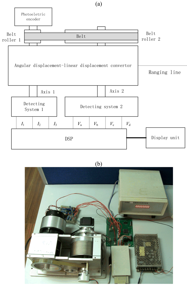
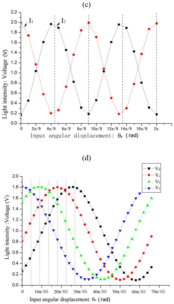
2. Principle and Configuration
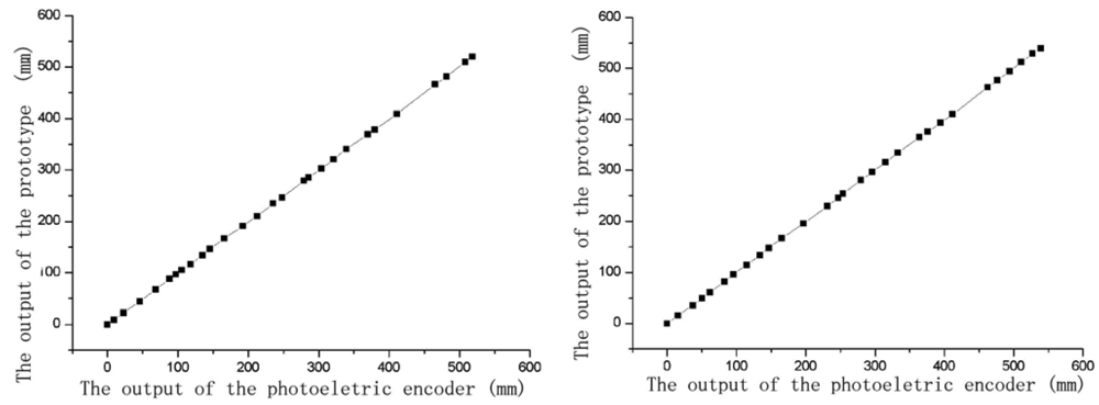
3. Prototype and Experiment
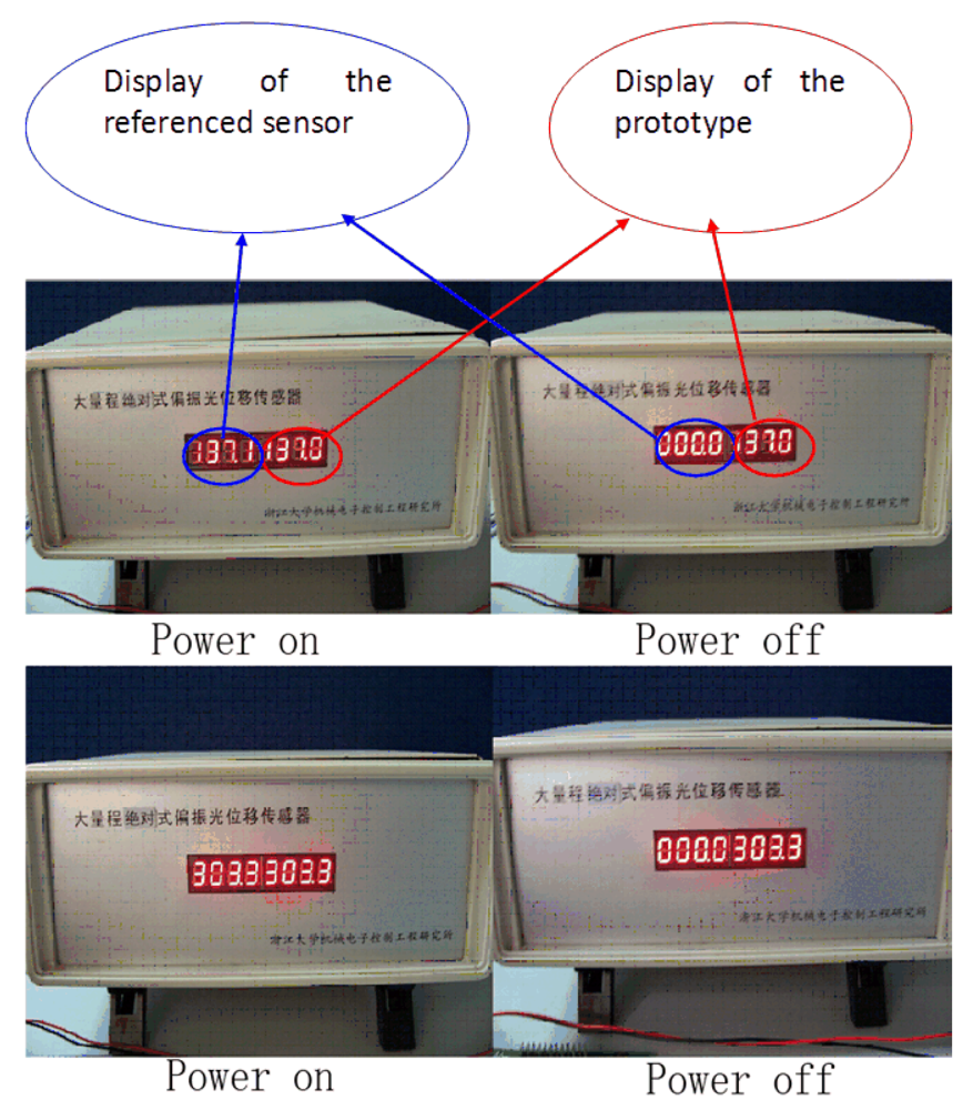
- No extra displacement is generated when power supply is off. First, draw the ranging line to a set point, record the output of the sensor, after that cut off the current supply, then turn on the supply after a few minutes, and record the new output. While the power is off, the ranging line is kept at the set point. The results are shown in Figure 7.
- Extra displacement is generated when power supply is off. First, mark several position points, record their displacement values, after that cut off the power supply, and pull the ranging line to the marked points from random position, and then turn on the supply, record the new display of the sensor. The results are shown in Table 4.
4. Conclusions
Acknowledgments
References and Notes
- Liu, C. Practical Sensors., 3rd ed.; National defense industry Press: Beijing, China, 2004. [Google Scholar]
- Girão, P.M.B.S.; Postolache, O.A.; Faria, J.A.B.; Pereira, J.M.C.D. An overview and a contribution to the optical measurement of linear displacement. IEEE SENS. J. 2001, 1, 322–331. [Google Scholar]
- Kanoun, O.; Tränkler, H.-R. Sensor technology advances and future trends. IEEE Trans. Instrum. Meas. 2004, 53, 1497–1501. [Google Scholar]
- Lu, G. Latest Development of displacement measuring technology and its sensor. World Man. Eng. Market 2005, 4, 72–73. [Google Scholar]
- Goldstein, D. H.; Collett, E. Polarized Light; CRC Press: Boca Raton, FL, USA, 2003. [Google Scholar]
- Busurin, V.I.; Semenov, A.S.; Udalov, N.P. Optical and fiber-optic sensors (Review). Quantum Electr. 1985, 15, 595–621. [Google Scholar]
- Takahashi, G.; Sato, T.; Higaki, M.; Mori, E.; Okumura, K.; Kanoi, M. Optical voltage and current measuring system for electric power systems. IEEE Trans. Power Delivery 1986, 1, 91–97. [Google Scholar]
- Rudd, Robert, E., III. Polarizerless magneto-optic speed and torque sensor. US Patent 5,192,862, 1993. [Google Scholar]
- Deng, X.Y.; Li, Z.; Peng, Q.; Liu, J.; Tian, J. Research on the magneto-optic current sensor for high-current pulses. Rev. Sci. Instr. 2008, 79, 0831061–0831064. [Google Scholar]
- Duncan, W.M.; Celii, F.G.; Henck, S.A.; Paranjpe, A.P. Temperature sensor and method. US Patent 5,501,637, 1996. [Google Scholar]
- Mori, H.; Asahara, Y. Linearity of the Faraday-rotation-type ac magnetic-field sensor with a ferrimagnetic or ferromagnetic rotator film. Appl. Optics 1996, 35, 1083–1087. [Google Scholar]
- Sawa, T.; Kurosawa, K.; Yokota, T.; Kaminishi, T. Development of optical instrument transformers. IEEE Trans. Power Delivery 1990, 5, 884–891. [Google Scholar]
- Villaverde, A.B.; Munin, E.; Pedroso, C.B. Linear displacement sensor based on the magneto-optical Faraday effect. Sensor. Actuator. 1998, 139, 211–215. [Google Scholar]
- Li, W. Research on the principle and method of polarized light displacement sensor. Chin. J. Sci. Instrum. 1999, 20, 221–224. [Google Scholar]
- Li, S.; Yang, C.; Zhang, E.; Jin, G. Compact optical roll-angle sensor with large measurement range and high sensitivity. Optic. Lett. 2005, 30, 242–244. [Google Scholar]
- Li, W.; Lu, Y. A polarized light rectilinear displacement sensor with nonlinear precorrection. Chin. J. Sci. Instrum. 2000, 21, 58–60. [Google Scholar]
- Li, W.; Lu, S. An optical displacement sensor with wide measuring range. IEEE Sensors 2004 Conference, Vienna, Austria, October 24-27, 2004.
- Li, W.; Wang, Y.; Ma, J. Research on displacement-current comparator. J. Zhejiang Univerisity 2004, 38, 860–863. [Google Scholar]
- Hao, S.; Liu, Y.; Hao, M. Study on a novel absolute magnetic grating. Elec. Mach. Contr. 2008, 12, 451–454. [Google Scholar]
- Bi, H.; Li, G.; Li, Y. Measuring displacement using absolute rotary encoder. J. Transducer Technol. 1998, 17, 48–53. [Google Scholar]
- Liao, Y.; Luo, W. A way of validating Malus law. Phys. Exp. 2001, 21, 24–26. [Google Scholar]


| Periodical order number i | Discriminant |
|---|---|
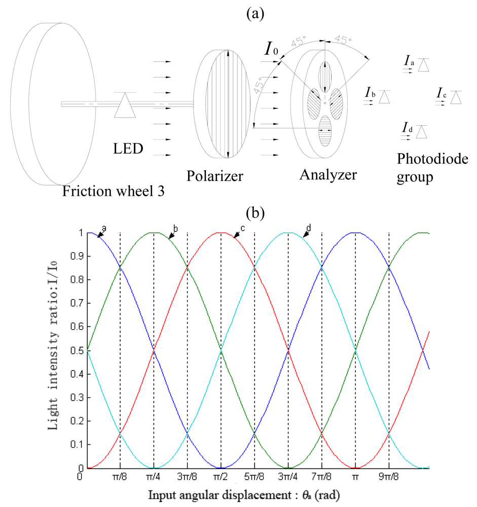
| 1 | Ia > Ib ≥ Id > Ic |
| 2 | Ib ≥ Ia > Ic ≥ Id |
| 3 | Ib > Ic ≥ Ia > Id |
| 4 | Ic ≥ Ib > Id ≥ Ia |
| 5 | Ic > Id ≥ Ib > Ia |
| 6 | Id ≥ Ic > Ia ≥ Ib |
| 7 | Id > Ia ≥ Ic > Ib |
| 8 | Ia ≥ Id > Ib ≥ Ic |
| Periodical order number i | Discriminant |
|---|---|
| 1 | Va > Vb > Vc > Vd |
| 2 | Vb ≥ Va > Vc > Vd |
| 3 | Vb > Vc ≥ Va > Vd |
| 4 | Vc ≥ Vb > Vd ≥ Va |
| 5 | Vc > Vd ≥ Vb > Va |
| 6 | Vd ≥ Vc > Vb > Va |
| Point 1 (mm) | No. | Output (mm) | Point 2 (mm) | No. | Output (mm) | Point 3 (mm) | No. | Output (mm) |
|---|---|---|---|---|---|---|---|---|
| 110.0 | 1 | 110.5 | 240.0 | 1 | 240.4 | 480.0 | 1 | 480.2 |
| 2 | 110.5 | 2 | 240.4 | 2 | 480.2 | |||
| 3 | 110.6 | 3 | 240.4 | 3 | 480.2 | |||
| 4 | 110.5 | 4 | 240.5 | 4 | 480.2 | |||
| 5 | 110.5 | 5 | 240.4 | 5 | 480.2 | |||
| 6 | 110.5 | 6 | 240.5 | 6 | 480.2 | |||
| Repeatability error (mm) | 0.1 | Repeatability error (mm) | 0.1 | Repeatability error (mm) | 0.0 | |||
| No. | Calibration displacement value (mm) | Output (mm) |
|---|---|---|
| 1 | 59.8 | 59.8 |
| 2 | 124.6 | 124.6 |
| 3 | 191.6 | 191.6 |
| 4 | 302.7 | 302.7 |
| 5 | 379.7 | 379.7 |
| 6 | 509.2 | 509.2 |
© 2009 by the authors; licensee Molecular Diversity Preservation International, Basel, Switzerland. This article is an open access article distributed under the terms and conditions of the Creative Commons Attribution license (http://creativecommons.org/licenses/by/3.0/).
Share and Cite
Li, W.; Lu, X.; Lin, Y. Novel Absolute Displacement Sensor with Wide Range Based on Malus Law. Sensors 2009, 9, 10411-10422. https://doi.org/10.3390/s91210411
Li W, Lu X, Lin Y. Novel Absolute Displacement Sensor with Wide Range Based on Malus Law. Sensors. 2009; 9(12):10411-10422. https://doi.org/10.3390/s91210411
Chicago/Turabian StyleLi, Wei, Xiaoping Lu, and Yonggang Lin. 2009. "Novel Absolute Displacement Sensor with Wide Range Based on Malus Law" Sensors 9, no. 12: 10411-10422. https://doi.org/10.3390/s91210411