A Flexible Flow Sensor System and Its Characteristics for Fluid Mechanics Measurements

Abstract
:1. Introduction
2. Sensor Design and Fabrication
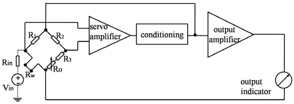
2.1. Sensing Principle
2.2. Substrate and Sensing Elements
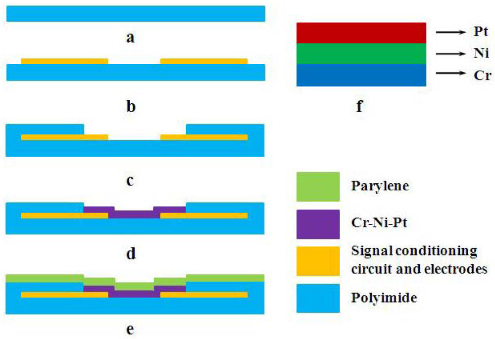
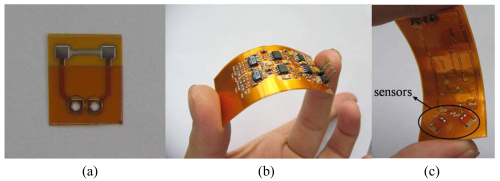
2.3. Fabrication
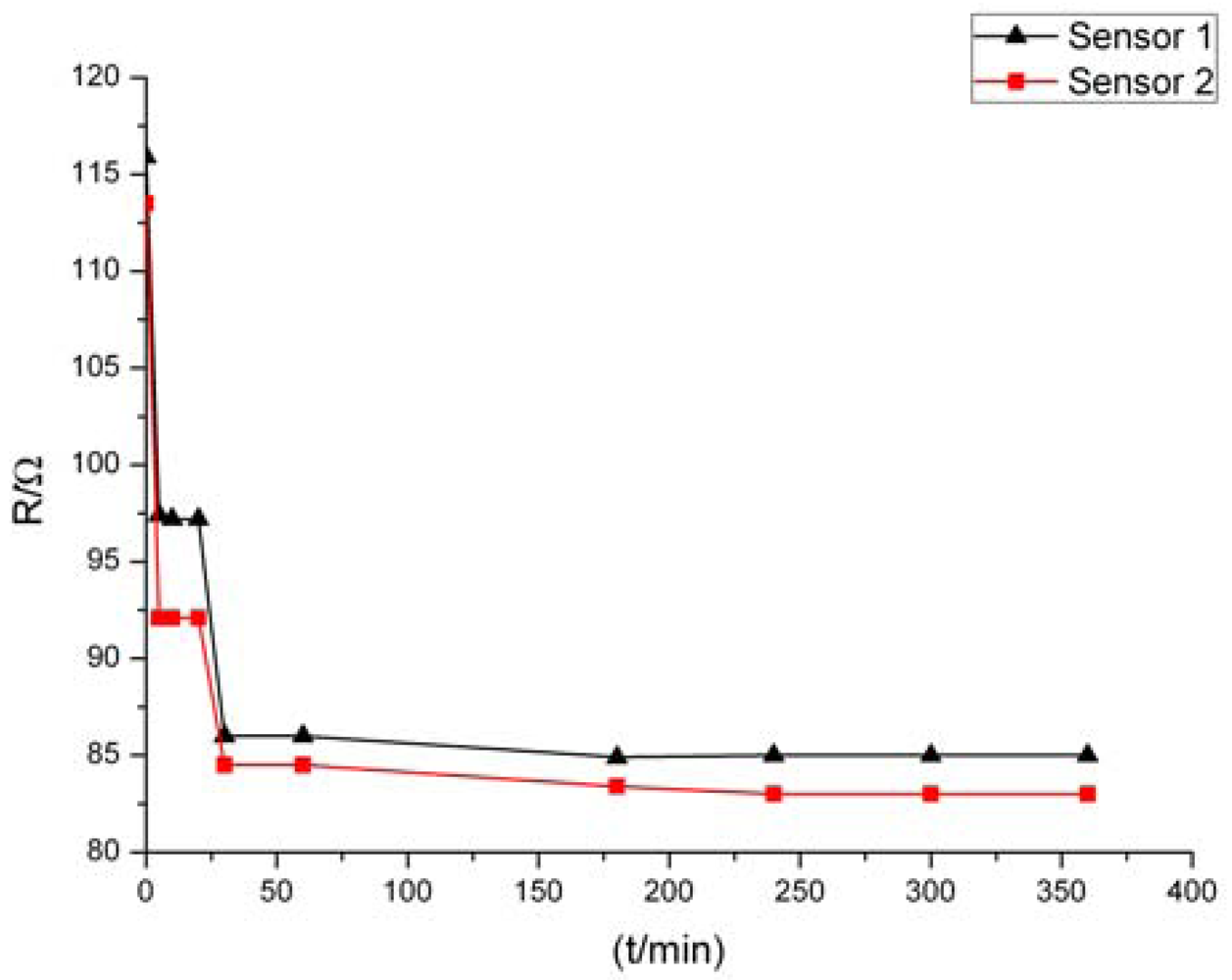
2.4. Post Treatment
3. Sensor Characteristics
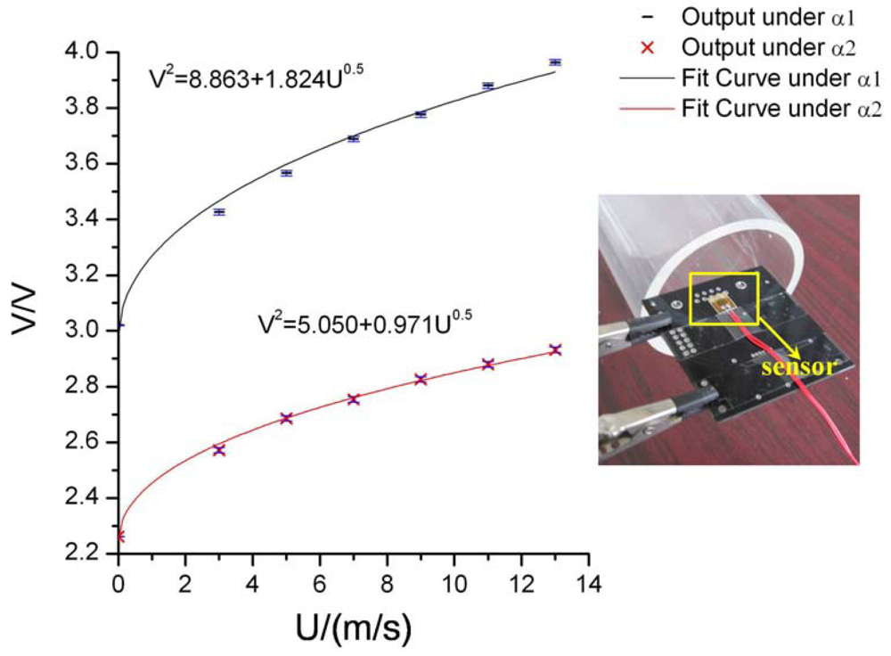
3.1. Sensor Calibration
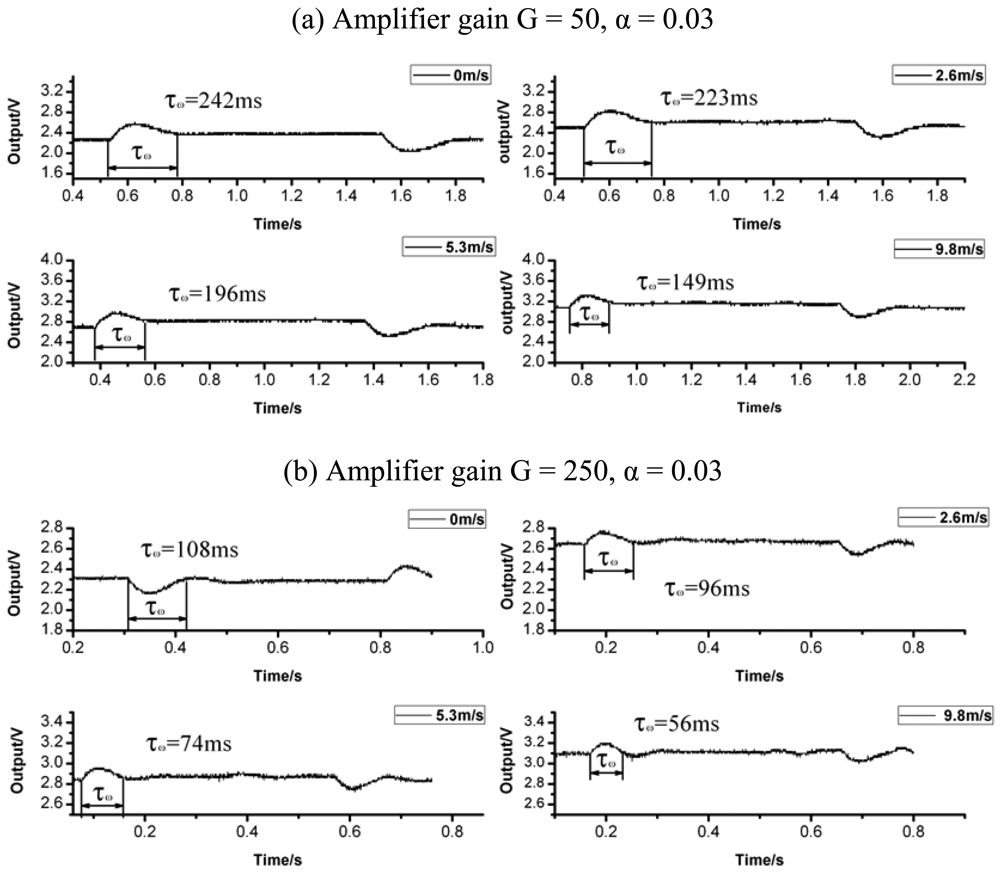
3.2. Dynamic Response
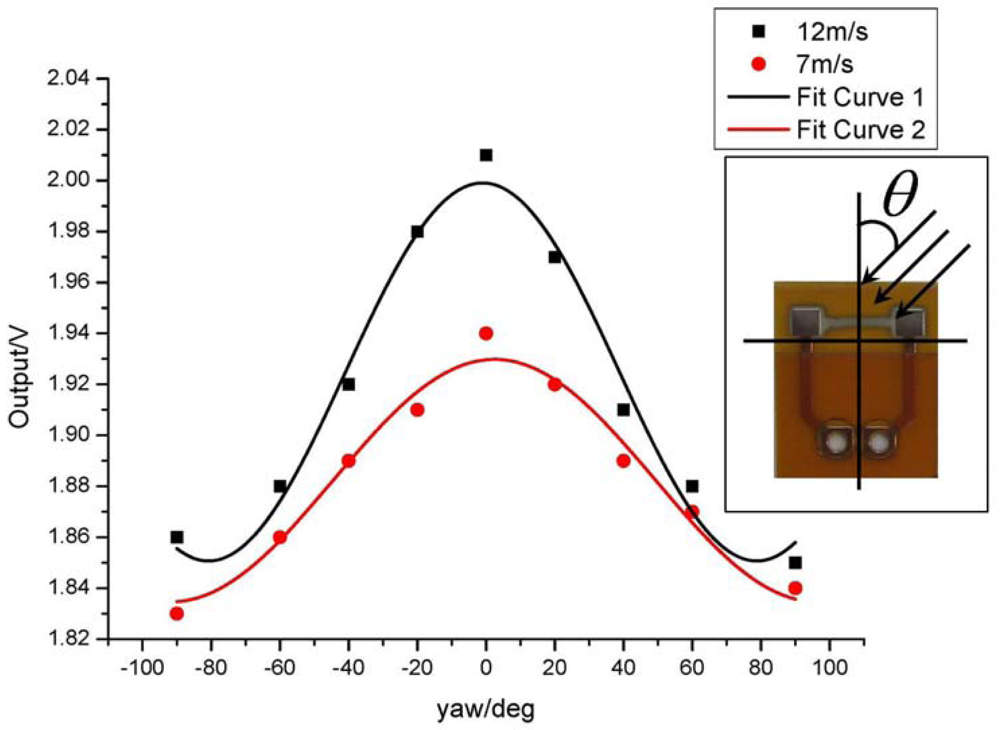
3.3. Directional Sensitivity
3.4. Characteristic Analysis and Applications
4. Conclusions
Acknowledgments
References and Notes
- van Putten, A.F.P.; Middelhoek, S. An integrated silicon anemometer. Electron. Lett. 1974, 10, 425–426. [Google Scholar]
- Chen, J.; Fan, Z.F.; Zhu, J. Two-dimensional micromachined flow sensor array for fluid mechanics studies. J. Aerospace Eng. 2003, 16, 85–97. [Google Scholar]
- van Baar, J.J.; Wiegerink, R.J.; Lammerink, T.S.J. Micromachined structures for the thermal measurements of fluid and flow parameters. J. Micromech. Microeng 2001, 11, 311–318. [Google Scholar]
- Chen, J.; Liu, C. Development and characterization of surface micromachined, out-of-plane hot-wire anemometer. J. Microelectromech. Syst. 2003, 12, 979–988. [Google Scholar]
- Huang, A.; Lew, J.; Xu, Y.; Tai, Y.C.; Ho, C.M. Microsensors and actuators for microfluidic control. IEEE Sens. J. 2004, 4, 494–502. [Google Scholar]
- Henning, A.K. Microfluidic MEMS for semiconductor processing. IEEE Transducer 98 1998, B21, 329–337. [Google Scholar]
- Lofdahl, L.; Kalvesten, E.; Hadzianagnostakis, T.; Stemme, G. An integrated silicon based wall pressure-shear stress sensor for measurements in turbulent flows. Proceedings of 1996 International Mechanical Engineering Congress and Exposition, Atlanta, GA, USA, November 17–22, 1996; pp. 245–251.
- Olsson, A.; Enoksson, P.; Stemme, G.; Stemme, E. A valve-less planar pump isotropically etched in silicon. J. Micromechanic. Microengineer 1996, 6, 87–91. [Google Scholar]
- Boillat, M.A.; van der Wiel, A.J.; Hoogerwerf, A.C. A differential pressure liquid flow sensor for flow regulation and dosing systems. Proceedings of IEEE Micro Electro Mechanical Systems, Amsterdam, The Netherlands, January 29–February 2, 1995; pp. 350–352.
- Padmanabhan, A.; Goldberg, H.; Breuer, K.D.; Schmidt, M. A wafer bonded floating element shear stress microsensor with optical position sensing by photodiodes. IEEE J. Microelectromech. Syst. 1996, 5, 307–315. [Google Scholar]
- Xu, Y.; Jiang, F.; Lin, Q.; Clendenen, J.; Tung, S.; Tai, Y.C. Under water shear stress sensor. Proceedings of 15th IEEE International Conference on Micro Electro Mechanical System, Las Vegas, NV, USA, January 20–24, 2002; pp. 340–343.
- Budera, U.; Petzb, R; Kittelb, M.; Nitscheb, M.; Obermeier, E. AeroMEMS polyimide based wall double hot-wire sensors for flow separation detection. Sensor. Actuat. A–Phys. 2008, 142, 130–137. [Google Scholar]
- Li, C.; Wu, P.M.; Han, J.; Ahn, C.H. A flexible polymer tube lab-chip integrated with microsensors for smart microcatheter. Biomed. Microdevices 2008, 10, 671–679. [Google Scholar]
- Callegari, S.; Zagnoni, M.; Golfarelli, A.; Tartagni, M.; Talamelli, A.; Proli, P.; Rossetti, A. Experiments on aircraft flight parameter detection by on-skin sensors. Sensor. Actuat. A–Phys 2006, 130–131, 155–165. [Google Scholar]
- Xu, Y.; Tai, Y.C.; Huang, A.; Ho, C.M. IC-integrated flexible shear-stress sensor skin. J. Microelectromech. Syst. 2003, 12, 740–747. [Google Scholar]
- Bruun, H.H. Hot-wire anemometry; Oxford University Press: Oxford, UK, 1995. [Google Scholar]
- Perry, A.E. Hot-Wire Anemometry; Clarendon Press: Oxford, UK, 1982. [Google Scholar]
- Freymuth, P. Frequency response and electronic testing for constant-temperature hot-wire anemometers. J. Phys-E-Sci. Instrum. 1977, 10, 705–710. [Google Scholar]
- Nguyen, N.T. A novel thermal sensor concept for flow direction and flow velocity. IEEE Sens. J. 2005, 5, 1224–1234. [Google Scholar]
- Liu, P.; Zhu, R.; Liu, X.D.; Zhang, F.X.; Zhou, Z.Y. A low-cost integrated micro system for flow velocity and direction measurement. Proceedings of the 15th International Conference on Solid-State Sensors, Actuators and Microsystems, Denver, USA, June 21–25, 2009; pp. 276–279.
- Fei, H.P.; Zhu, R.; Zhou, Z.Y.; Wang, J.D. Aircraft flight parameter detection based on a neural network using multiple hot-film flow speed sensors. Smart Mater. Struct. 2007, 16, 1239–1245. [Google Scholar]


| Flow velocity / (m/s) | 0 | 2.6 | 5.3 | 9.8 |
| Time constant τc of (a) / ms | 314.6 | 289.9 | 254.8 | 193.7 |
| Time constant τc of (b) / ms | 140.4 | 124.8 | 96.2 | 72.8 |
| Flow rate range | 0–15 m/s (α = 0.03) |
| Angular sensitivity range | 0–60° |
| TCR | 2,000 ppm/°C |
| Inaccuracy | ±3% F.S. |
| Repeatability | ±0.3% F.S. |
| Response time | τc = 72.8 ms (G = 250, α = 0.03, 9.8 m/s) |
| Zero adjustment | Overheat ratio dependent |
| Supply voltage | 8VDC ± 10% |
| Output signal | 1.5 V–4.5 V |
| Resolution | 0.1 m/s |
| Power consumption | 30 mW(G = 50, α = 0.03, 5 m/s) |
© 2009 by the authors; licensee Molecular Diversity Preservation International, Basel, Switzerland. This article is an open access article distributed under the terms and conditions of the Creative Commons Attribution license (http://creativecommons.org/licenses/by/3.0/).
Share and Cite
Liu, P.; Zhu, R.; Que, R. A Flexible Flow Sensor System and Its Characteristics for Fluid Mechanics Measurements. Sensors 2009, 9, 9533-9543. https://doi.org/10.3390/s91209533
Liu P, Zhu R, Que R. A Flexible Flow Sensor System and Its Characteristics for Fluid Mechanics Measurements. Sensors. 2009; 9(12):9533-9543. https://doi.org/10.3390/s91209533
Chicago/Turabian StyleLiu, Peng, Rong Zhu, and Ruiyi Que. 2009. "A Flexible Flow Sensor System and Its Characteristics for Fluid Mechanics Measurements" Sensors 9, no. 12: 9533-9543. https://doi.org/10.3390/s91209533