1. Introduction
The mobile
ad-hoc network, MANET [
1], is a developing wireless technology that has been discussed in many academic research projects in the last decade. An
ad-hoc network is inherently a self-organized network system without any infrastructure. Typically, the nodes act as both host and router at the same time, i.e., each node in the network can be independent and based on different hardware, but when communication is needed it serves as a data transmitting router after a route discovery procedure.
So far, many routing protocols have been proposed for MANET, such as DSDV (Destination Sequence Distance Vector) [
2], DSR (Dynamic Source Routing) [
3] and AODV (Ad-hoc On-Demand Vector) [
4] and so on. To the best of our knowledge, most previous research has focused on protocol establishment and its efficiency in MANET, but secure routing is very important, and some secure routing protocols based on DSR and AODV [
5-
7] have been proposed in these years.
Recently, a novel exploit called
wormhole attack was introduced [
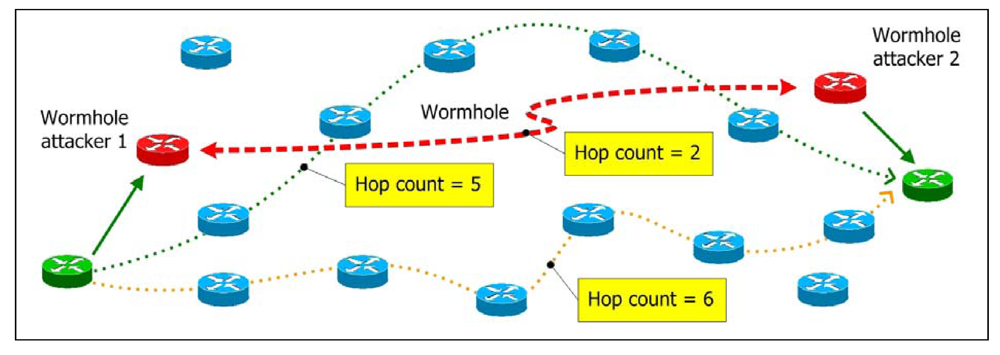
8]. In a wormhole attack, attackers “tunnel” packets to another area of the network bypassing normal routes as shown in
Figure 1. In practice, attackers can use high power antennas or a wired link, or other methods. The resulting route through the wormhole may have a better metric, i.e., a lower hop-count than normal routes. With this leverage, attackers using wormholes can easily manipulate the routing priority in MANET to perform eavesdropping, packet modification or perform a DoS (Denial of Service) attack, and so on. The entire routing system in MANET can even be brought down using the wormhole attack. Its severity and influence has been analyzed in [
9].
Most previous works protecting against wormhole attack use methodologies assuming the viewpoint of administrator, trying to identify the wormhole, and then defend against it. They can further be classified as centralized systems like MDS-VOW (
Multi-Dimensional Scaling -Visualization of Wormhole) [
10], and distributed systems such as LBK (
Local Broadcast Key) [
11]. Some require substantial calculation and some others employ special nodes in the network. These methods consume effort and bandwidth as overhead. There are other similar schemes such as TIK protocol, SAM, DelPHI and LITEWORP which will be summarized in Section 2.
Instead of the viewpoint of administrator, we adopt the viewpoint of users and utilize routing information already available in standards like RFC3561. The concept is that we don't have to spend a lot of effort to catch thieves like the police (administrators), but rather lock the doors and windows as citizens (users), which is much easier and can avoid most of the threats with minimum effort. Our method selects routes and “avoids” rather than “identify” the wormhole resulting in low cost and overhead. We propose a multipath routing protocol called Multipath Hop-count Analysis (MHA, for short) to avoid wormhole attacks based on a hop-count analysis scheme. It is a highly efficient protocol which does not require any special supporting hardware. Furthermore, MHA is designed to use split multipath routes, so the transmitted data is naturally split into separate route. An attacker on a particular route can not completely intercept (and subvert) our content.
The rest of the paper is organized as follows: We review related works regarding wormhole attack in Section 2. In Section 3, the MHA protocol is proposed. The simulations are given in Section 4, and then comparison and discussion are provided in Section 5. Finally, we present our conclusions and future work in Section 6.
3. A Proposed Robust Scheme Based on Hop-Count Analysis (MHA)
3.1. The Concept of MHA
We illustrate the concept of MHA in
Figure 2. The normal routes for a particular communication pair contain 5∼6 hops; the route under a wormhole attack has a hop-count of 2. We see the route under the wormhole attack has a smaller hop-count than normal. As a result, users who avoid routes with relatively small hop-counts can avoid most wormhole attacks.
In MHA, we first examine the hop-count values of all routes. Then we choose a safe set of routes for data transmission. Finally, we randomly transmit packets through safe routes. Even if the wormhole is not avoided in some severe cases, we can still minimize the rate of using the route path through the wormhole. The simulation results are shown in Section IV.
In our work, we refer to RFC3561 [
4], i.e., the AODV routing protocol, to set up MHA. We use the control packets as in RFC3561 and modify them to satisfy our requirements. Their modified functions are defined in the following section. For example, the RREQ packet is used for route discovery and the RREP packet is used for route reply, and so on.
Figure 3 shows the RREQ packet format in MHA. While most fields stay as they were in RFC 3561, in addition, we define a field called
check flag (CF), which is used with RREQ ID to distinguish new RREQ packets from old ones in MHA. The CF is also included in the RREP packet. A RREQ packet with CF = 0 is served as a normal route discovery, while CF ≠ 0 represents the
graylist broadcast, which is introduced in section 3.3. The source node triggers the graylist broadcast based on the result of hop-count analysis.
The MHA contains four parts. The route establishment is introduced in Section 3.2, and graylist broadcast is illustrated in 3.3. The hop-count analysis scheme is proposed in 3.4. Finally, the route maintenance method is given in 3.5. The notations used are listed in
Table 1.
3.2. Route Establishment in MHA
The source node launches a route discovery procedure if there is a communication requirement. It first adds IP
S, IP
D and RREQ ID in the RREQ packet, then sets the hop-count = 0 and attaches an expiration time to the RREQ packet. Later, the RREQ packet is broadcasted into the network and received by surrounding nodes. In
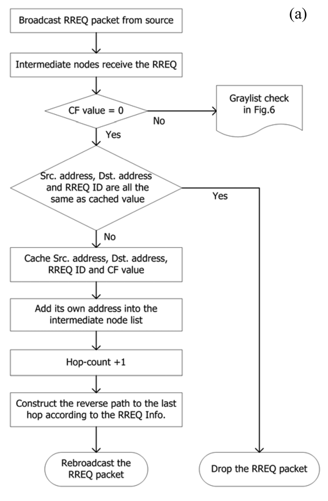
Figure 4(a), the nodes which receive the RREQ packet process it as follows:
Check CF to confirm the broadcast type. When CF = 0, examine IPS, IPD and RREQ ID with cached values;
If all values are the same, drop the packet;
If not, cache IPS, IPD, RREQ ID and CF;
Add its own IP address into the intermediate list;
Hop-count + 1;
Construct a route back to where the RREQ packet came from;
Rebroadcast the RREQ packet and switch to waiting mode. The nodes in this mode can only used for transferring control packets.
With the flooding of RREQ packets, the destination node finally receives them. The destination node then generates the RREP packets with following steps:
Copies IPS, IPD, RREQ ID and CF from the RREQ packet and writes in the corresponding field of the RREP packet, then sets the hop-count = 0;
Unicasts the RREP packet to the source node through each route.
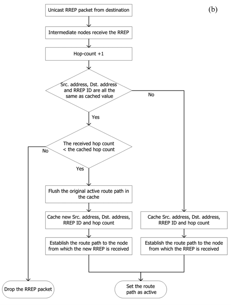
In
Figure 4(b), when intermediate nodes receive the RREP packet, they process it as follows:
The destination node then establishes a route back to where the RREP packet came from and sets the route as active thus it can be used for transferring data packets.
3.3. RREP number limit and Graylist Broadcast
The RREP packets are finally sent back to the source node. In our MHA protocol, we set a
RREP number limit (RREP
lim) to consider the reasonable amount of routes that are found in a route discovery procedure. This is designed for a special circumstance in attacking RFC 3561. In
Figure 5, there is a wormhole between a communication pair. Due to the better metric of the wormhole, the RREQ packet rebroadcast by the wormhole is accepted by the nodes around the destination node at first. Consequently, the RREQ packets which are flooded from the normal nodes later will be dropped. As a result, only the route through the wormhole can be established.
The RREPlim can prevent this situation. This value can be adjusted according to the network circumstances. For example, in a highly trusted environment, where most nodes consist of familiar people, we can safely decrease the RREPlim value in the route discovery procedure. First, we set the default RREPlim, such as RREPlim = 2. After the source node receives all RREP packets, it compares the number of received RREP packets γ with RREPlim. If γ < RREPlim, it probably means that there is a wormhole, or too few nodes in the network. The source node then launches the graylist broadcast in this situation.
The graylist broadcast contains the following steps:
CF + 1 in the RREQ packet;
Adds all intermediate nodes which are found in the last route discovery procedure into the graylist;
Broadcasts the RREQ packet with the graylist.
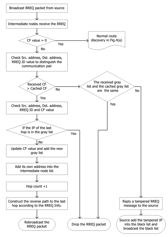
In the graylist broadcast illustrated by
Figure 6, the nodes handle the received RREQ packet in following steps:
Check CF to confirm the broadcast type. When CF ≠ 0, check IPS, IPD and RREQ ID to determine the communication pair;
Compare CF with the cached value;
If it is the same as the cached one, check the received graylist with the cached one;
If they are the same, drop the packet;
If some values in the graylist are suspected to be modified by the malicious nodes, alert the source node of the modified value. The source node then marks the suspect IP address in the blacklist The blacklisted nodes will not be used for a period;
If CF is larger than the cached one, update the CF and graylist in the memory and check if the last hop in the RREQ packet is in the graylist;
If the last hop has been recorded in the graylist, drop the packet; if not, add its own IP address into the intermediate list;
Hop-count+1;
Construct a route back to the RREQ packet came from;
Rebroadcast the RREQ packet and enter the waiting mode of this route.
The destination node receives the RREQ packet and replies RREP packets as usual. Finally, the source node receives the new RREP packets with a larger CF. The source node compares γ with RREP
lim again and triggers another graylist broadcast until at least one of the following conditions is true:
γ ≥ RREPlim;
CF = 7. Considering efficiency, CF value in MHA reserves 3 bits, i.e., CFmax = 7;
No RREP packet reply, perhaps due to a too small quantity of nodes in the network.
After the source node completes the route discovery and graylist broadcast, it continues to the hop-count analysis and route path selection mechanism.
3.4. Hop-Count Analysis Scheme and Route Selection
In MHA, a route with too low or too high hop-count is considered unhealthy. A too low hop-count may imply a wormhole attack; while a too high hop-count may decelerate the transmission. Furthermore, a route with a high hop-count has a higher chance to break.
In MHA, we define random variable
X which represents the hop-count values in the received RREP packets, and
U = {
x1, …,
xi, …,
xj, … } is the sample space of random variable
X. So we have its cumulative distribution function
FX(x). We further define variables
α and
β which represent the lower bound and upper bound of the selected range on
FX(x), then
m and
n will be the corresponding hop-count boundaries. They are defined in
Equation (1) as follows:
Finally, we select the route paths from received RREP packets with hop-count x
r which satisfies
Equation (2):
as legal route paths in MHA protocol. The legal route paths are cached in the source node and given a TTL. Data packets are then transmitted randomly through these routes. If any of these legal route paths are broken, the source node deletes it from the cache. If all legal route paths are broken or vanished, and there is still a requirement for communication, the source node will carry out another route request procedure.
In addition, the source node unicasts route acknowledgement (RACK) packets along all legal routes to the destination node before the first data packet is sent. The RACK packet contains the intermediate nodes of all legal routes and the expiration time. The destination node then caches them for further transmission. Once this step is completed, the bidirectional routes of a communication pair are established.
3.5. Route Maintenance in MHA Routing Protocol
3.5.1. Dealing with Broken Routes and RERR Packets
As time passes, routes may break. When a node receives a data packet but can not reach the next hop in the routing table, it generates a RERR packet including IPS and IPD to notify the source/destination node.
The source/destination node receives the RERR packet, deletes the broken route in memory and uses the RACK packet to notify the destination/source node to use other remaining routes. The destination/source node also deletes the route. Until the next route discovery procedure, the remaining routes are used for transmission.
3.5.2. Cross-check the Route Paths
In the MHA protocol, we give an expiration time for every route. All intermediate nodes delete the cached route after expiration to conserve memory. However, in certain environments, the nodes in the network may be static. These routes may persist over time. In order to have better efficiency, when routes of a communication pair are expired but are still in use, the source node unicasts a RACK packet with a new expiration time to the destination node through the valid routes. The intermediate nodes and the destination node then refresh the expiration time in their routing table.
Consequently, we limit resource usage and recover some overhead that would originally be wasted by launching unneeded route discovery procedures. We also save memory of intermediate nodes that would otherwise be used for keeping idle routes.
4. Simulations
To test our method, we develop an event driven simulator by using C and Matlab. The C program is used to set up the simulation environment and compute the actions of all nodes between route discovery processes. Then, we visualize the simulation results by using Matlab.
We assumed each node is distributed randomly by the simulator, and each node will send and receive packets with different delays in an allocated range. The source establishes a route discovery and graylist broadcast by sending the RREQ packet. In response, the destination node replies with RREP packets. The source node then selects the legal routes.
Furthermore, the simulator allows users to input the RREPlim value for each simulation. We can input different RREPlim for each simulation, and the simulator completes the graylist broadcast as required.
In this section, we give four experiments to show the performance of the proposed protocol. In
Table 2, we give the parameters used in the experiments.
4.1. Experiment 1 - Maximum Wormhole Effect
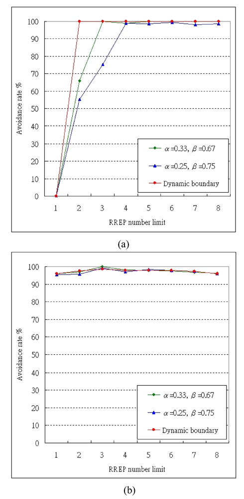
In Exp. 1, we verify the avoidance rate of the maximum wormhole effect. That is, the wormhole is placed in the middle of the communication pair and other normal nodes are placed at random.
Figure 7(a) shows the avoidance rate with different legal boundaries (α, β).
We apply three kinds of boundaries in this experiment. With loose boundaries of (0.25, 0.75), only the routes with hop-counts in the middle 1/2 distribution are selected as legal. As a result, the avoidance rate is higher than 98% when RREPlim ≥ 4. With stricter boundaries of (0.33, 0.67), the avoidance rate is higher than 99% when RREPlim ≥ 3.
Nevertheless, we design a dynamic boundary. We apply different boundaries (α, β) according to the received RREP numbers, e.g., we choose (0.5, 1) for received RREP number = 2, and (0.35, 1) for received RREP number = 3∼4, and (0.25, 0.75) for received RREP number = 5∼6, and so on. The dynamic boundary gives a better percentage in avoiding wormhole attacks and also enhances the performance by decreasing transmission distance in hops. Refer to
Figure 5(a), as long as RREP
lim ≥ 2, the avoidance rate can reach 100%.
However, the wormhole attack is unavoidable when RREPlim = 1 for any boundaries, because the only established route goes through the wormhole. As the RREPlim increases, the avoidance rates of all boundaries raise. The effect on a strict boundary is more obvious than it is on a loose boundary.
4.2. Experiment 2 - Random Wormhole Effect
In Exp. 2, we verify the avoidance rate of the random wormhole effect, that is, all nodes including the wormhole and the communication pair are distributed at random. Then, we compare the effects of different boundaries and show its result in
Figure 7(b).
In this experiment, the effect from adjusting boundaries is not as clear as it is in Exp. 1. This is because the random wormhole does not have the best metric to some particular transmission pairs in routing. In this case, the inherent multipath transmission nature of MHA exhibits protection against wormholes by splitting data into different routes, so the attacker cannot launch further attacks.
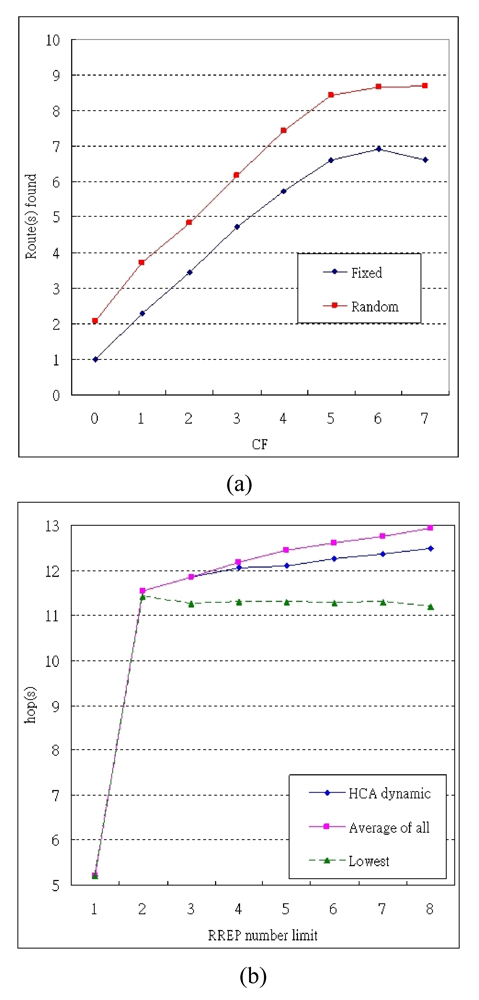
4.3. Experiment 3 & 4 - Overhead of MHA
In Exp. 3, we examine the number of routes that have been found in each graylist broadcast under both maximum and random wormhole effect. The number of routes found for CF from 0 to 7 is shown in
Figure 8(a).
In Exp. 4, we examine the transmission distance in MHA with dynamic boundary under the maximum wormhole effect. The lowest hops, i.e. the route found with AODV without wormhole, and average hops, i.e. the average of all available routes, are also shown together in
Figure 8(b).
5. Discussion and Comparison
5.1. Discussion
In Exp. 1, the avoidance rate of maximum wormhole effect is verified. We find when MHA applied with constant boundaries, the strict boundaries performs better than the loose ones in avoiding wormhole attack and the simulation result is shown in the
Figure 5(a). The curve of the strict boundary rises faster than the loose one with the growth of RREP
lim value. Furthermore, we present the dynamic boundary, which changes with the received RREP number, in order to improve accuracy and efficiency. As a result, it can avoid 100% of wormhole attacks when RREPlim ≥ 2. In Exp. 2, the avoidance rates for all RREP
lim are over 96%.
In Exp. 3, at CF = 1, i.e., only one graylist broadcast is needed, 2.3 and 3.74 routes are found on average under the maximum and random wormhole effects, respectively. Compared with Exp. 1 and Exp. 2, it performs with 100% and 96% avoidance rates, respectively. As a result, we can conclude that only one graylist broadcast is required for avoiding wormhole attacks, and further minimize overhead. In addition, multi-wormhole cases that have not been discussed in other previous works can be avoided by increasing the RREPlim value in MHA. On the other hand, if there is no wormhole within a closed environment, the graylist broadcast can be cancelled by setting RREPlim = 1 to save energy and bandwidth.
In Exp. 3, we also find in our assumed environment, most independent routes can be found when CF < 6. In Exp. 4, the transmission distance of MHA is longer than the shortest route by about one hop, but below the average of all routes. This is because with MHA, the routes with higher hops are also filtered out. In addition, the shortest route can represent the route discovered by AODV in safe environments. It shows our judicious use of an extra hop (on average) to grant us a great amount of protection against wormhole attacks in comparison to AODV.
Our method provides good performance for avoiding wormhole attacks, but there could be some attacks anticipating MHA. For example, attackers may add fake nodes to an intermediate list so the route has a longer distance. However, it is quite hard for attackers to correctly estimate the expected hops of a particular communication pair since they do not know their relative position. In addition, since we only select part of the searched routes for multi-path transmission, the probability that attacks can occupy the route are further reduced. In another scenario, attackers may maliciously modify other nodes instead of itself in the graylist. Thus the nodes that have been modified would be reported as modifiers and be blocked by the source node. To counter this, some ID-based cryptographic methods [
19] such as digital signatures can be adopted to prevent this.
5.2. Comparison
Most of the protocols proposed in literature can reach high avoidance rates in their experiments. However, they all need some impractical assumptions or special hardware as listed in
Table 3. The MHA routing protocol does not need impractical assumptions, such as precise synchronized time, zero delay time, or the awareness of all node locations, and so on, which are usually assumed in the schemes adopting the viewpoint of administrator. In addition, MHA does not need any special hardware either. Due to its simple concept, the hop-count analysis scheme can improve most routing protocols in MANET as well. The nodes only need to sort the received hop-counts, and select the legal ones according to the preset boundaries. Thus the computation overhead is very low for this process.
We compare MHA with previous works in
Table 3. In [
9], a large amount of hash tree computation is required. In their discussion, the optimized condition performs 10 million hash function evaluations in 7.544 seconds on a Pentium III running at 1 GHz; and 45 seconds on a Compaq iPAQ 3870 PocketPC running Linux. A long waiting time for system setup shows their high overhead. In [
11], all transmissions between node pairs have to be encrypted by the local broadcast key of the sending end and decrypted at the receiving end. As a result, the time delay accumulates per node traveled. The MDS-VOW mechanism in [
10] uses a control center to accomplish the
O(n3) operations if there are n nodes. This is a fairly heavy load for the control center.
6. Conclusion and Future Works
In this paper, a novel scheme based on an intuitive method to avoid wormhole attacks in MANET is proposed. The defining characteristic of this method is avoiding wormhole attacks from the viewpoint of users instead of the administrator's viewpoint as in previous works. We provide four simulations to show the proposed scheme has high efficiency and very good performance with low overhead. In addition, this scheme does not require additional hardware or impractical assumptions of the networks. Hence, it can be directly used in MANET.
Although we have proposed a solution for the wormhole attack problem in MANET, the dynamic information of the packets could still be modified. This issue can be solved by some cryptographic method, such as a homomorphic one-way hash function. The static data, i.e. payload, can be secured by ID-based signature. These methods can also be adopted for MHA to give a more robust protection in some special scenarios like battlefields, which need a highly secured environment.


