Article

Designing and Testing Composite Energy Storage Systems for Regulating the Outputs of Linear Wave Energy Converters

1
Department of Electrical Engineering, Tsinghua University, Beijing 100084, China
2
Zinergy Shenzhen Ltd., Taohuayuan Science and Technology Innovation Park, Baoan, Shenzhen 518101, China
3
Zinergy UK Ltd., Future Businesss Centre, Cambridge CB4 2HY, UK
4
The Warwick Manufacturing Group, University of Warwick, Coventry CV4 7AL, UK
5
Department of Electronic and Electrical Engineering, Bath University, Bath BA2 7AY, UK
*
Authors to whom correspondence should be addressed.
Energies 2017, 10(1), 114; https://doi.org/10.3390/en10010114
Submission received: 7 August 2016 / Revised: 29 December 2016 / Accepted: 6 January 2017 / Published: 18 January 2017
(This article belongs to the Special Issue Numerical Modelling of Wave and Tidal Energy)

Abstract

:
Linear wave energy converters generate intrinsically intermittent power with variable frequency and amplitude. A composite energy storage system consisting of batteries and super capacitors has been developed and controlled by buck-boost converters. The purpose of the composite energy storage system is to handle the fluctuations and intermittent characteristics of the renewable source, and hence provide a steady output power. Linear wave energy converters working in conjunction with a system composed of various energy storage devices, is considered as a microsystem, which can function in a stand-alone or a grid connected mode. Simulation results have shown that by applying a boost H-bridge and a composite energy storage system more power could be extracted from linear wave energy converters. Simulation results have shown that the super capacitors charge and discharge often to handle the frequent power fluctuations, and the batteries charge and discharge slowly for handling the intermittent power of wave energy converters. Hardware systems have been constructed to control the linear wave energy converter and the composite energy storage system. The performance of the composite energy storage system has been verified in experiments by using electronics-based wave energy emulators.

1. Introduction

As a large untapped renewable source, electricity can be harnessed from ocean waves [1,2,3,4], and this could contribute a significant portion of the electricity needed to meet world-wide consumption. Most current research into harnessing energy from ocean waves has focused on developing the mechanical system for the capture of energy from the ocean sources, rather than the conversion methods of the irregular electrical power from wave energy converters. Conventional wave energy converters, such as the oscillating-water-column system and the pendulum-type, usually need intermediate mechanical systems for kinetic energy conversion from the low frequency of ocean waves to the high frequency of conventional generators. This reduces the overall system efficiency. Linear wave energy converters (LWECs) directly use the kinetic energy of the floating body driven by ocean waves. As the energy conversion from low frequency to high frequency is not needed, it is an attractive technology with advantages of reduced complexity, reduced maintenance and system cost [5,6,7,8,9,10,11,12,13]. At the same time, appropriate control and power conversion methods need to be developed for linear wave energy converters, to increase the efficiency of electrical power extraction and conversion.
Traditional point absorbing wave energy converters employ either a linear electric generator or a linear-to-rotary mechanism. Rack-pinion, slider-crank or ball-screw mechanisms are usually employed in linear-to-rotary systems [8]. Among the linear-to-rotary mechanisms, the ball-screw mechanism is useful in transforming a slow linear motion into a fast rotary motion with a high efficiency (more than 90%), and this is suitable for use in point absorbing wave energy converters [14,15]. It is well-known that linear generators outweigh rotational ones because of the simplicity and effectiveness of the total structure [16]. In a LWEC, a linear electrical machine is directly coupled to the driving source, for example a floating buoy. When the linear machine is coupled to the motion of a floating buoy, a characteristic electromotive force (EMF) is induced in the machine’s coils. Varying ocean waves with slow and cyclic motions generate corresponding EMF waveforms. An example of the usual electrical output is shown in Figure 1 and is similar to that presented in [6,7].
When the translator of a LWEC reaches the ends of its stroke with a frequency of twice that of ocean waves, the linear machine is being reset and the power output is zero at these two instants. Hence, a large fluctuation occurs in the output power of linear wave energy converters, and with a varying time period of seconds. In addition, like wind power and all other renewable sources, ocean power may vary significantly according to sea states, resulting in a long term variation of the output power of wave energy converters, varying from minutes to hours.
A wave energy converter ideally should provide steady power to the local load or grid, and its output power should be regulated to maintain a desired value over a time of hours or more. This paper describes the methods for extracting powers from a LWEC and conditioning the fluctuating output power. A composite energy storage system composing of super capacitors and batteries is presented to operate in conjunction with the wave energy converter. The composite energy storage system overcomes the variations of powers outputted from wave energy converters, by providing temporary storage ability over a few wave cycles and long term storage ability up to hours, thereby meeting the goal of providing a steady output power. Moreover, the batteries are prevented to handle the frequent fluctuations of LWECs, and are like have longer life and less maintenance. The control systems of linear wave energy converters and the composite energy storage system are simulated by MATLAB software and the experimental results will be given to verify the performance of the composite energy storage system by using an electrical wave energy emulator.

2. Proposed System

Linear wave energy converters can be considered a variable frequency generator, and the output is conventionally conditioned by controlled rectification. Therefore, a stable DC link voltage could be provided for supplying an inverter bridge to feed the grid. The DC link bus is a suitable location for the connection of energy storage to be used as a buffer for leveling the power output. A composite energy storage system is presented for handling the output power fluctuations of linear wave energy converters and achieving the constant power-flow requirement. The proposed system includes a high power density device (super capacitor) and a high energy density device (battery), as shown in Figure 2.
The operation of a linear wave energy converter is expected to last for many years in the offshore marine environment, as performing maintenance in the offshore marine environment is expensive, hazardous and time consuming. The power generated from wave power can be transmitted to the shore either by underwater AC or high voltage DC transmission cables, depending on the distance, as planned in the UK for the connection of offshore wind farms. Hence, it is a feasible option to place the super capacitor system offshore with the LWEC while the battery system resides onshore, as super capacitors have much longer lifetimes than batteries [4].

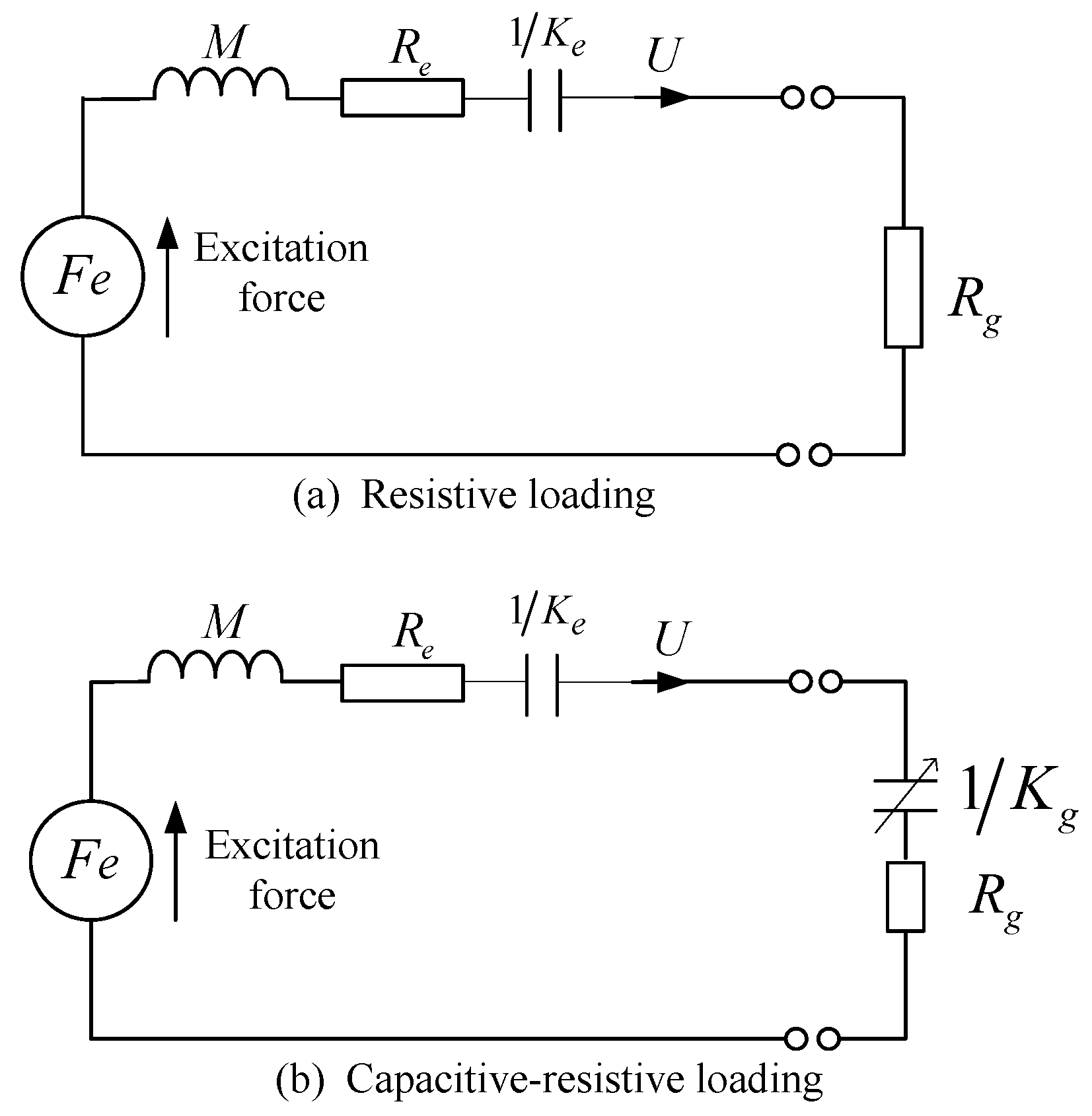
3. Controls of Linear Wave Energy Converters (LWECs)

A number of linear electrical machines have been designed for direct drive methods of harnessing wave power [5,6,10,11,12,17]. The comparatively large internal inductance of the generator coils of some linear machines results in a low power factor, as noted by Ran and Hodgins [11,17]. Hence, these machines require substantial reactive power compensation in order to increase their output power factors. An alternative linear machine design, the tubular linear machine [10], can achieve power factors above 0.95 in wave application. However, there is a tradeoff between improved power factor and power density, as tubular linear machines has large internal resistance
The energy harvesting system of a LWEC can be modelled as a mass-spring-damper system, as described in [18], and as shown in Figure 3, where F e is the excitation force; U is the device translational velocity; M is the device mass; 1 / K e is the inverse of the spring stiffness force constant; and R e is the total resistance of the mechanical damping.
The load impedance seen by a LWEC depends upon the control strategy of the generator, which can be purely resistive or can present some capacitive reactance to cancel that of the energy harvesting system. The resistive and capacitive-resistive loadings are represented in Figure 3a,b, respectively. A linear system could output maximum power by damping the system in resonance [18]. In this approach, maximum power extraction takes place when the load damping equals the mechanical losses.
In other words, all impedance terms in the generator loading system are controlled to achieve maximum power transfer, as expressed by Equations (1) and (2):
R g = R e
K g = ω 2 M K e
Even taking the uncertainty and errors of parameters into consideration, a maximum power point tracking (MPPT) control strategy can be employed to achieve maximum power extraction [19]. Two AC/DC power converter topologies have been proposed to control the power extraction from LWECs: one is a unidirectional topology [11,20] based on diode rectifiers and designed especially for the high power factor machines as mentioned before; the other topology is based on an H-bridge or full bridge which allows bidirectional power flow [6,21,22,23,24]. Although the unidirectional topology offers cost savings, the bidirectional topology is necessary for cancelling the machine’s dynamic reactance, and to allow a reversible energy exchange for tuning a resonant arrangement of mechanical power take-off. Therefore, the bidirectional H-bridge topology shown in Figure 4 is adopted in this paper.
The AC power from LWECs with slowly varying amplitude and frequency, must be entirely controlled by a bidirectional H-bridge converter to improve the power extraction from LWECs, and is required to be rectified and regulated to a desired DC link voltage. Moreover, the DC link voltage value is generally higher than the induced EMF in the generator coils of LWECs so a boost function is required. The generator coil Lcoil could be exploited as boost inductor, for the purpose of achieving lower power loss and avoiding an additional component. The free boost inductor or the generator coil is connected in front of the H-bridge. IGBTs and fast recovery diodes could be adopted for the H-bridges, but the switching frequency is supposed to be carefully controlled below the generator coil’s self-resonance frequency.
The currents of generator coils are controlled to track proportionally to the open loop output EMF of LWECs by switching the pairs (Z2 and Z4) and (Z1 and Z3) diagonally, and this aims to optimize the power flow from LWECs. In the positive cycle of EMF waveform, the generator coil is charging when Z2 and Z4 are turned on as shown in Figure 4a, otherwise it is discharging as shown in Figure 4b. Figure 4c,d shows the current flows of the H-bridge converter when EMF is in the negative cycle.
The free boost inductor has a value of more than 10 times the minimum inductance required for ensuring the continuous conduction mode (CCM) operation of the mentioned boost H-bridge [25,26,27,28]. In the continuous mode, the inductor current never reaches zero during any part of the switching cycle. There is no dead time gap between cycles, as shown in Figure 5. During the period ton, the IGBT switches are on and the inductor current increases from an initial value to a peak value i p , replacing the energy given up in the last cycle, energy being drawn from the input. When the IGBT switches are off, the diode conducts for the rest of the cycle toff, and i L falls to a lower value than i p . This lower value is the initial value of the next cycle, but never becomes zero unless Vin reaches zero. The inductor’s energy is transferred to the output during toff.

4. A Composite Energy Storage System

The intermittent and fluctuating power produced by a linear wave energy converter could be considered as low quality electricity, which is supposed to be regulated to a continuous and steady form to meet the connection requirements of the local load or power grid. These power quality concerns can be allayed by appropriate energy storage devices.

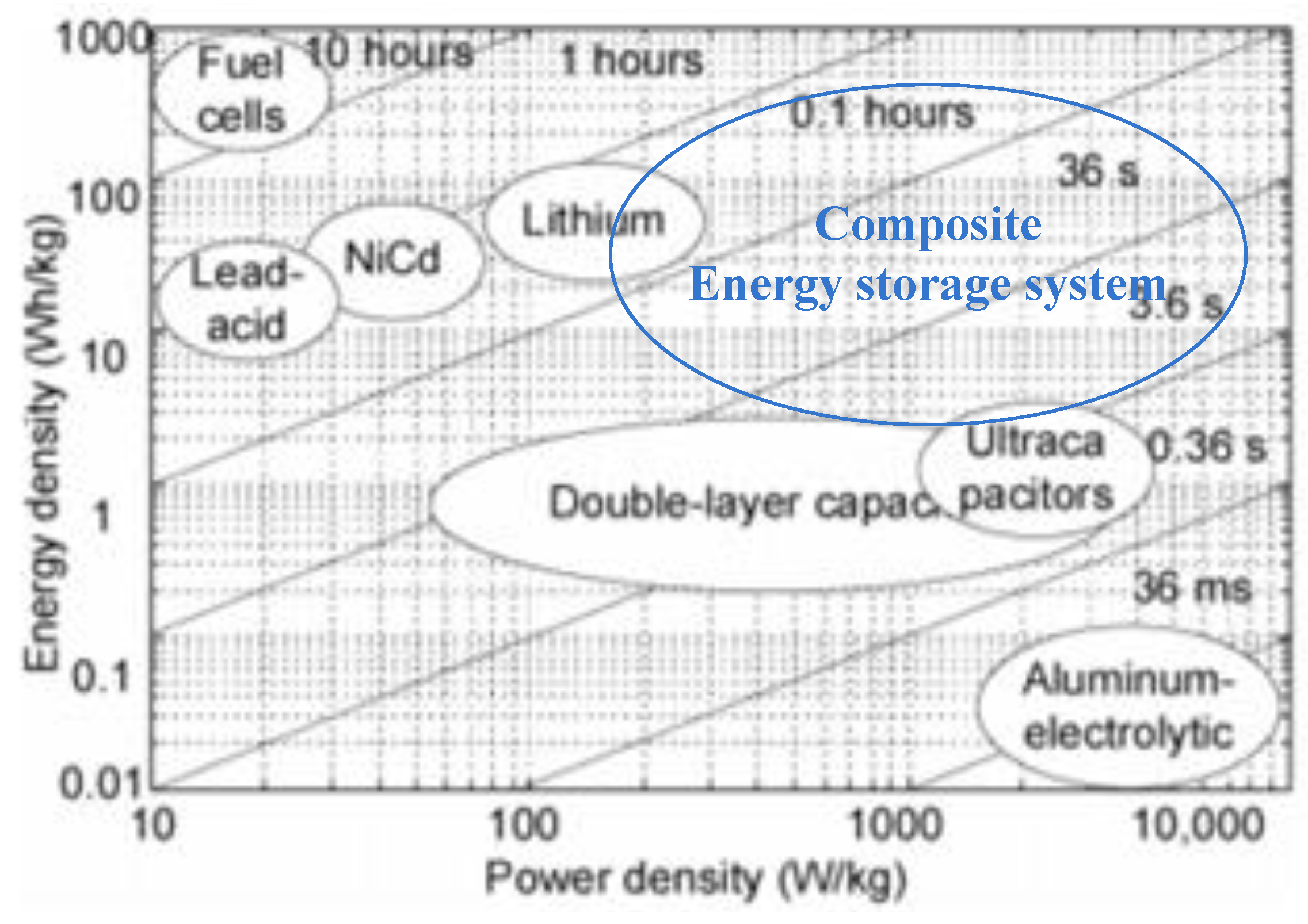
4.1. Energy Storage Components

Diverse energy storage techniques are summarized in [29,30,31,32], and they have various relative disadvantages and advantages. Referring to Figure 6 [29,30,31,32], the advantages of super capacitors are summarized as having a high power density, high efficiency and tolerance to a large number of charging cycles. Comparatively, batteries are characterised as having a large energy capacity, but the number of charging cycles is limited and the power density is relatively low. Batteries are not suited to handling frequent fluctuations in power systems and devices with a high power density are more capable of handling frequent varying fluctuations in power systems.
In the application of wave energy conversion, performing maintenance is difficult and uneconomical, especially for offshore installations. This paper proposes a composite energy storage system working with wave energy converters. The composite system not only combines the benefits of both batteries and super capacitors, but also extends the operation life of batteries, as the super capacitor is used to handle the frequent fluctuations of the system. Hence, the frequency of maintenance of the overall system can be decreased.
In consideration of device maturity and system cost, a composite energy storage system composed of Li-ion batteries and super capacitors is proposed. Super capacitors are applied to handle the frequently varying power fluctuations within a time period of less than a minute, for example the typical fluctuations of power outputs from LWECs in one wave period, referring to Figure 2. This goal is achieved to economise the consumption of the limited charging cycles of batteries. Long term power stability is provided by the Li-ion batteries over time periods of hours. The batteries absorb the excessive power when LWECs are generating more power than required by the local loads or grids. The batteries supply power to meet the load demand when the LWECs are generating insufficient power. A composite energy storage system combines the advantages of the high energy density and high power density characteristics of different devices as shown in Figure 6, and the super capacitors and batteries are complementary.

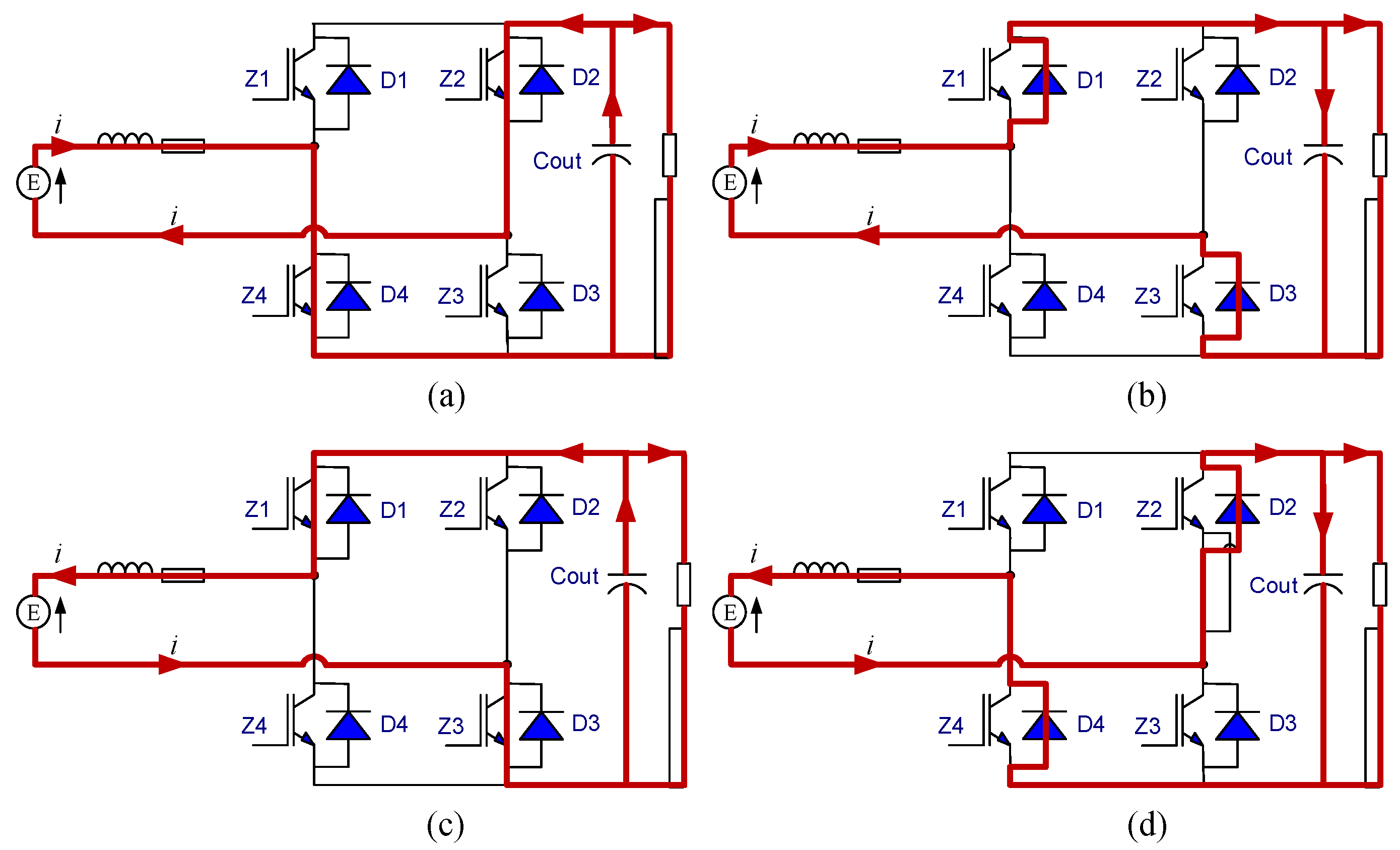
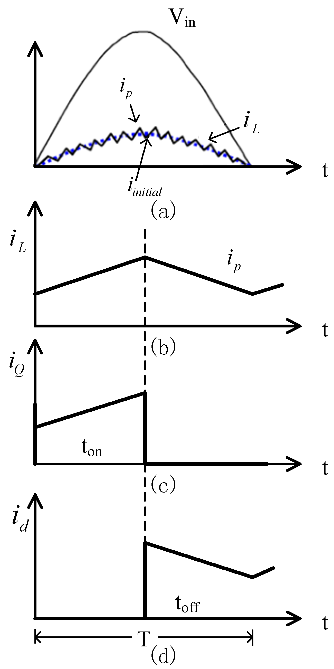
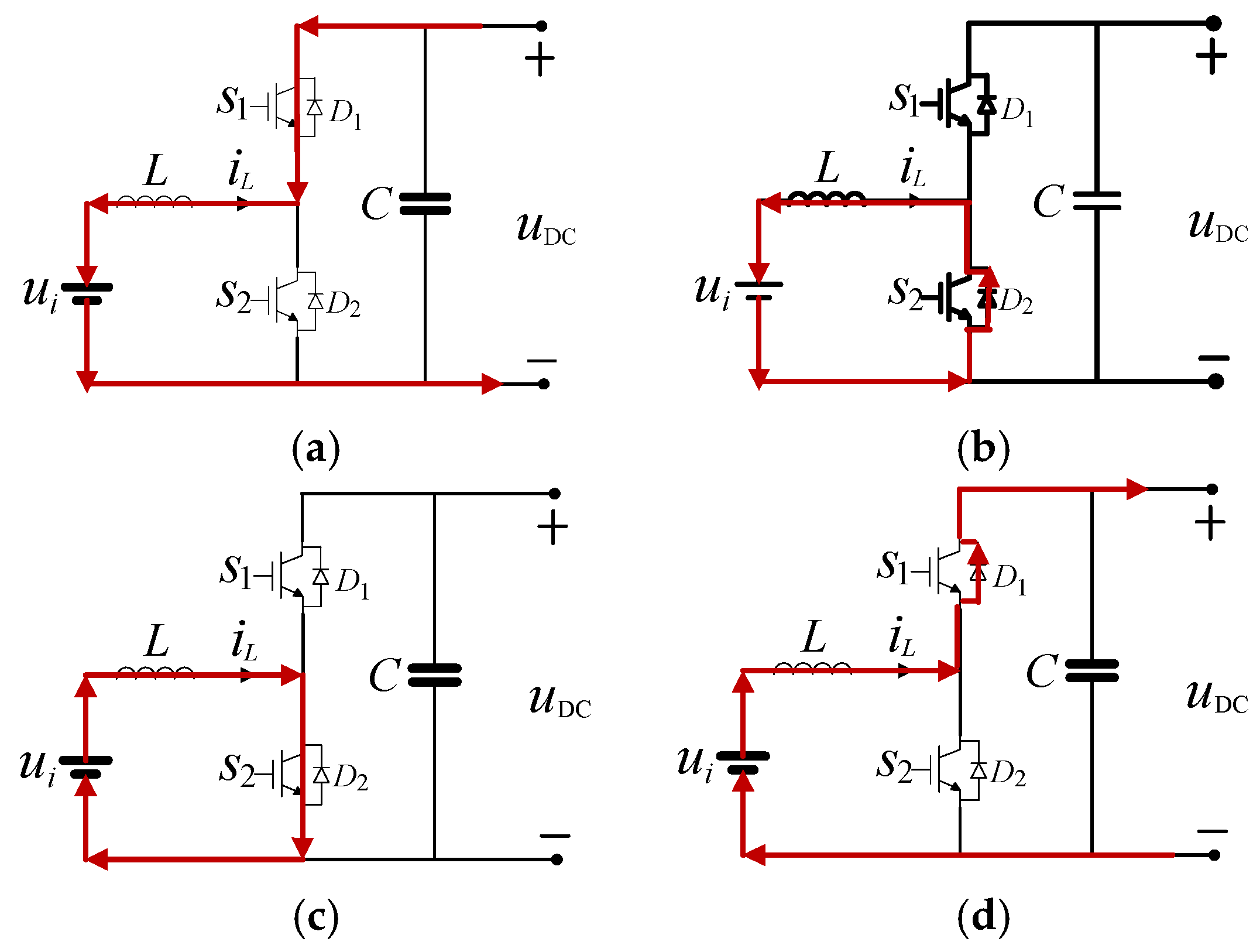
4.2. Interface Circuits

In Figure 2, the terminal voltage values of the batteries and super capacitors are generally smaller than the voltage value at DC link. A buck-boost DC/DC interface topology [33,34] is used for regulating the energy exchanges between energy storage systems and the DC link. The same converter topology is applied for both the super capacitors and batteries, as shown in Figure 7. The interface circuit operates in two different modes. In the buck mode, the energy storage device is charged by controlling S1, and extracts excessive power from the DC link. When S1 is on, current goes through S1, the inductor L and the electrical energy storage device are charged by the electrical power from the DC link. When S1 is off, the inductor L turns to discharge mode, current goes through D2, the electrical energy storage device is maintaining charge mode. In the boost mode, the terminal voltage of energy storage device is stepped up and release energy to DC link. When S2 is on, the energy storage device charges up inductor L. When S2 is off, the energy storage device and inductor L works in conjunction and both discharge energies to the DC link and maintain the DC link voltage.

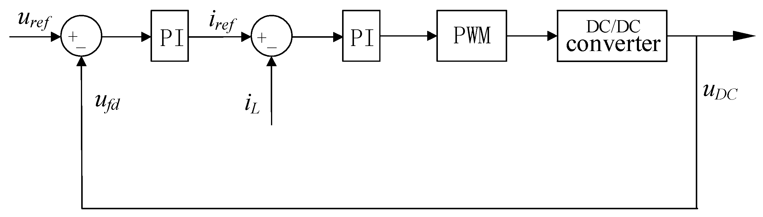
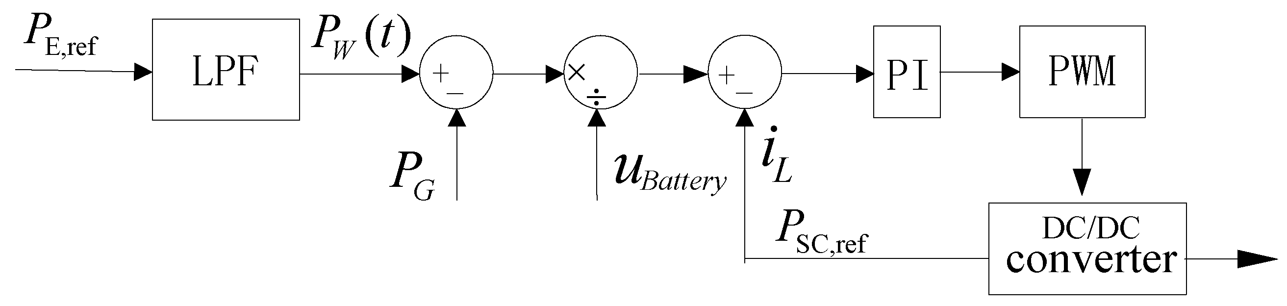
4.3. Control of Super Capacitors and Batteries

The super capacitors are connected to a DC Link by DC/DC bidirectional converters as shown in Figure 7. The voltage value of the DC link is maintained by the control method shown in Figure 8 using a proportional-integral controller. A feedback signal ufd is taken from the DC link. An error signal is obtained by subtracting ufd from a designed value of DC link voltage uref, and then fed to a proportional/integral stages (PI). A current reference iref is used to compare with iL the instant inductor currents of interface circuits shown in Figure 7, and then an error signal is generated and adjusted for generating pulse width modulation (PWM) signals to control the inductor currents.
The inductor current is fully controlled as shown in Figure 8, and the super capacitors and inductor are connected in series; this means the flows of currents or energy from the from the super capacitors are also fully regulated to maintain a steady DC link voltage. When the measured value of the DC link voltage is higher than the designed value u r e f , the super capacitors are controlled to operate in the buck mode for absorbing excess energy, thereby preventing the rise of the DC link voltage values. When the measured value of DC link voltages is smaller than u r e f , the circuit operates in the boost mode and supplies energy to maintain a steady DC link voltage.
The AC power generated from LWECs is extracted and converted to DC power. Low pass filters or moving average filters can be used to separate the DC and AC components of the power at the DC link. The AC power components (the frequent fluctuations) are suitably addressed by using super capacitors. LWECs are presumed to continuously supply a designed steady power P G to the local load or grid in a time intervals over hours, where P G is normally determined as the average power from LWECs predicted at a specific location. The different values between P G and P W ( t ) is addressed by batteries as shown in Equation (3), where P W ( t ) represents the varying DC component of power produced by LWECs.
P E ( t ) = P W ( t ) P G
When P E ( t ) is positive, the DC/DC converter is controlled to work in the buck mode as represented in Figure 7, and batteries absorb the excess power from LWECs. When P E ( t ) is negative, the DC/DC converter is controlled to function in the boost mode, and batteries release energy to DC link, aiming to retain steady values of power output P G and DC link voltage. Figure 9 describes the controls of the interface circuit of batteries.

4.4. Capacity of Energy Storage Component

In the application of harnessing ocean waves for electricity generation, the available amount of ocean power over a certain period can be forecasted. Accordingly, the power output amount P W ( t ) can be estimated for LWECs. The total energy capacity of batteries required in a composite energy storage system can therefore be determined by P E , which is the difference between the maximum power and the average power from LWECs at a particular location over a certain time. The maximum energy required to be stored by batteries can be evaluated as the integral of P E over a time interval t. Equation (4) shows the evaluation of Cbat the required capacity of batteries in A·h, where Vmax is the maximum terminal voltage and Vmin is the related minimum terminal voltage:
E bat = C bat ( V max + V min 2 )
The required capacity of super capacitors can be determined by a similar evaluation method. As described, the super capacitors generally respond faster than batteries, and hence are chosen to address frequent fluctuations of output powers from LWECs in a relatively short time period. Equation (5) shows the evaluation of Ccap the required capacitance of super capacitors:
E c a p = 1 2 C cap ( V max + V min 2 ) 2

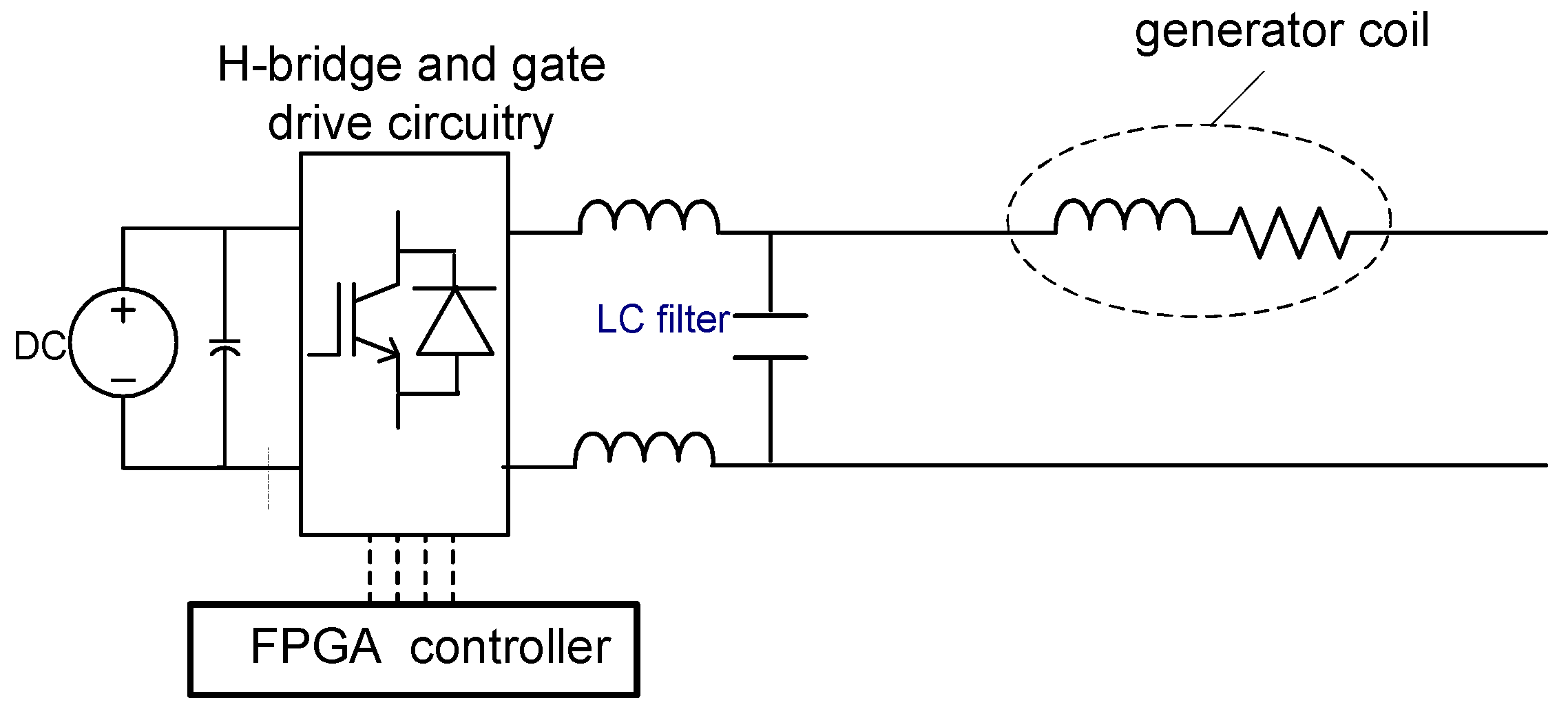
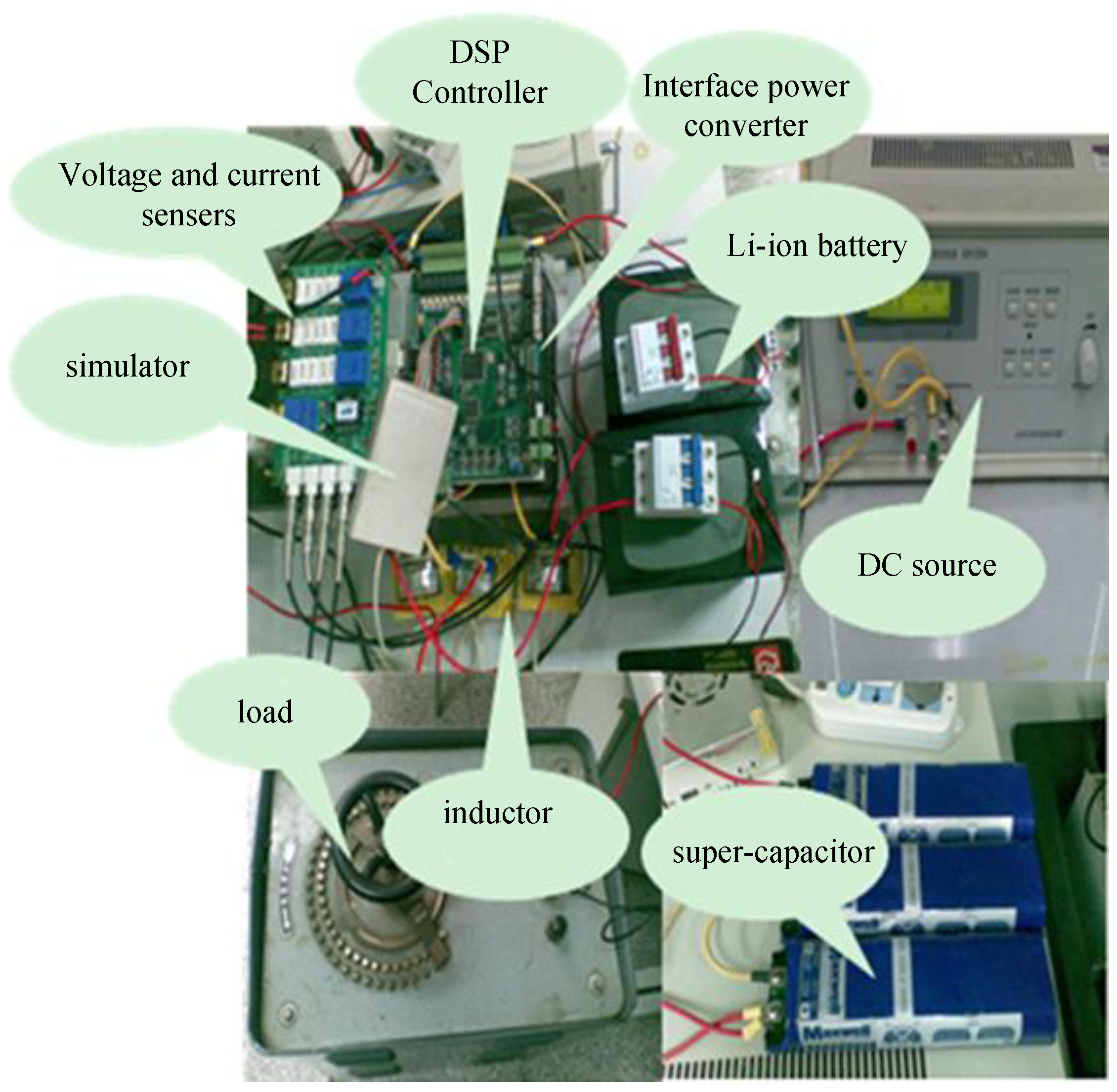
5. Hardware Implementation

A complete wave energy converter system could be tested in a wave tank facilities or at the sea, but this would be complicated, risky and costly. The investigation of control methods and power conversion strategies for LWECs requires repeatable wave conditions. Laboratory scale tests can imitate the characteristics of an individual wave energy converter, and provide cost savings and convenience.
A power electronics-based wave energy emulator is capable of emulating the impedances, power losses and voltage waveforms reflecting the expected outputs of a particular LWEC, as proposed in [35]. This emulator could be used to excite power converters and the power train of LWECs for the assessment of performances over a range of conditions. Referring to Figure 10, each phase of the wave energy emulator consists of a DC supply, a low pass filter, a section of coils from a particular linear machine, an H-bridge inverter and related control circuitries. The H-bridge is controlled by signals produced from a field programmable gate array (FPGA) based controller with PWM methods [36,37,38]. The low pass filter is used to remove the high frequency PWM components from the output of the H-bridge.
Figure 11 shows the experimental setup, which includes: two FPGA controllers, one for the AC/DC boost H-bridge and another one for the emulator; the H-bridges share the same heat sink. The AC/DC converters are built with four fast recovery diodes and four IGBTs, with ratings of 1200 V. A generator coil section from a small linear machine is used for replicating the source impedances of a particular generator. The coil has a resistance 20 Ω and an inductance 0.4 H. As the system is only emulating one coil section of a small prototype LWEC, the power level considered is low.
Figure 12 shows the experimental setup of the composite energy storage system, including Li-ion batteries with 51.2 V voltage rating and 6 A·h capacity, super capacitors with a total 52 F capacitance, and the related power converters and control circuits. The bi-directional dc-dc converters are built with IGBTs and fast recovery diodes, which are rated at 1200 V. Table 1 lists the parameter setup of the experiments.

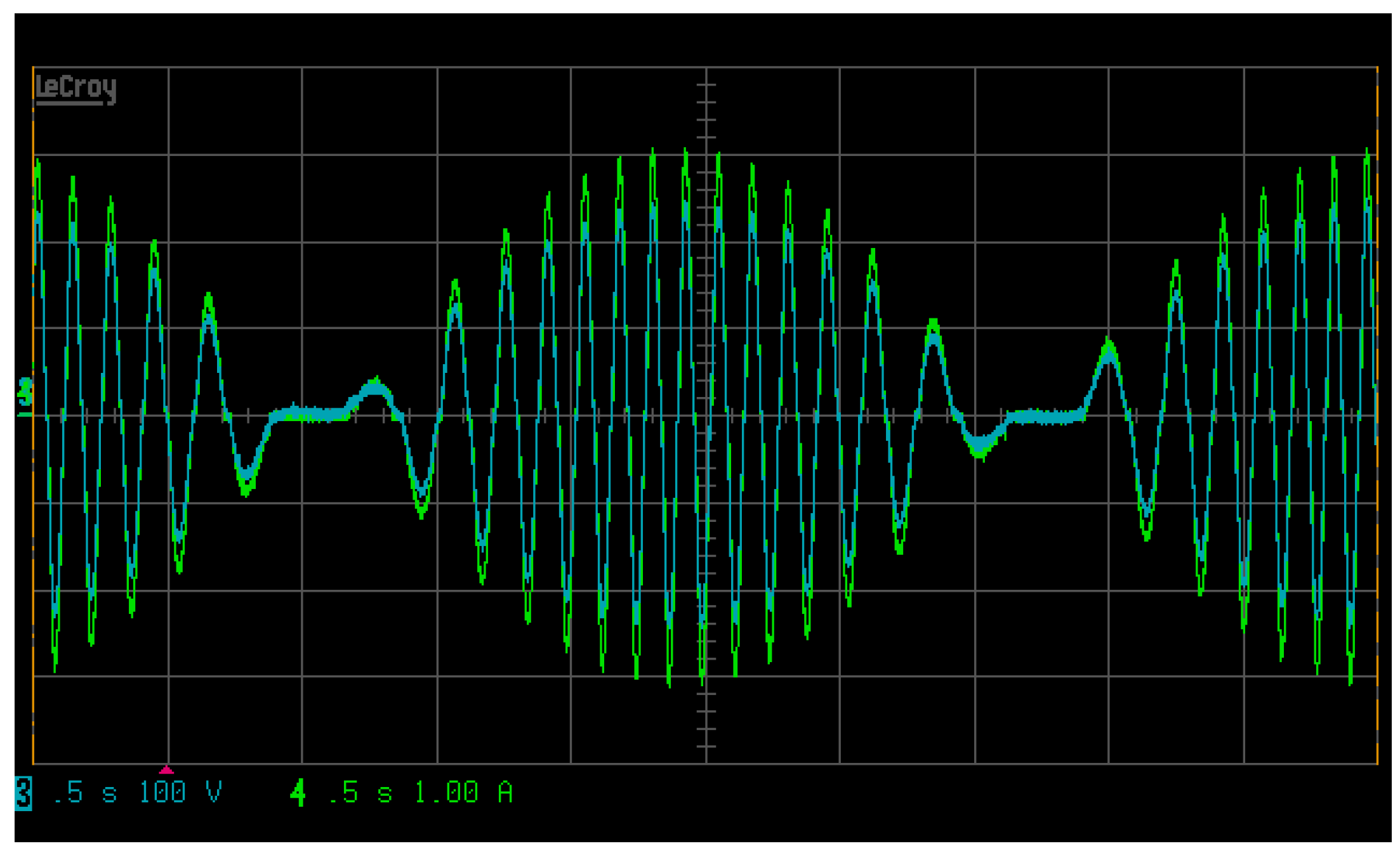
6. Results and Discussion

MATLAB is used to simulate the power converters and related control methods represented in this paper. These converters extract power from LWECs, and condition the output to a steady voltage and hence constant power for connecting to the load or grid. The open loop EMF waveforms are simulated for a LWEC, when it is driven by a particular ocean wave with 0.8 m amplitude and 5 s period, as shown in Figure 1. It can be seen that the expected voltage waveforms vary in both frequency and magnitude. The low frequency envelopes of voltage waveforms correspond to the input wave with a 5 s period. The frequency modulated EMFs are within the range 0–13 Hz. Since the translator of a LWEC will come to instantaneous rest at the ends of its stroke, it is clear that the mechanical power extracted must drop to zero at these positions, and power flow will be periodic with twice the wave frequency.
After passing through passive diode rectifiers, the currents from LWECs are discontinuous and small, and hence the extracted power and output voltage are relatively low, as shown in Table 2. In contrast, the AC/DC boost topology is capable of achieving quasi-continuous currents and higher DC link voltages. This results in the increase of output powers from 88 to 236 W. A small one-phase test rig is simulated at this stage, and 367 W is generated. However, a large amount of power is wasted due to the large intrinsic resistance of generator coils, and this result in only 236 W is extracted from the LWEC. The power level of a LWEC could be scaled up to kW or MW in real applications [10].
LWECs generate electrical power of varying frequency and amplitude, regardless of the state of the input driving ocean waves. Moreover, the power variation results a large ratio of peak to average power. As shown in Table 2, DC link voltages with large ripples are generated, which means using a capacitor even as large as 3 mF is ineffective. A large voltage ripple at the DC link is likely to cause challenges for maintaining the system’s stability and cause stresses on power electronics. The composite energy storage system of batteries and super capacitors has the ability of maintaining steady values of DC link voltage and power, but with a small voltage ripple of only 7 V.
Varying sea conditions will cause long term power variations from the LWECs. These can be handled by large energy density devices, in this case the batteries. Due to the limitations of computer resources, the simulation was performed for only four wave cycles as shown in Figure 13. The LWEC is desired to harnesses electricity from waves with amplitudes of 1.2 m and 0.8 m. As can be seen in Figure 13, the value of DC link voltage is maintained at 425 V by the composite system of various energy storage means. When the LWEC is driven by waves with 1.2 m amplitude, a 758 W average power is obtained from the generator, a steady power of 422 W is required by the local load and grid, and the excess amount of power is stored by the batteries. When the LWEC is driven by waves with 0.8 m amplitude, a 208 W average power is produced by the generator, and the batteries release energy for meeting the demand value of 422 W load.
The composite system of various energy storages is controlled to smooth the fluctuation of powers from LWECs and meet the steady power-flow requirement. As shown in Figure 14, the super capacitor is controlled according to the arrangement shown in Figure 8. When the green line or red line is positive, the super capacitors or batteries are in discharging mode, respectively. When the two lines are negative, the energy storage components are in charging mode. The charging and discharging processes of the super capacitors (indicated by green lines) are much more frequently than that of batteries (indicated by red line). This means that capacitor’s advantages are being exploited to cover the disadvantages of batteries including limited charging/discharging rates and charging/discharging cycles. On the other hand, the batteries have advantage of a large energy density, which could be applied to handle long term fluctuations of power.
The wave energy emulator produces the expected EMF envelope with similar amplitude and the same frequency, as compared to the simulation results shown in Figure 1 and the experimental results shown in Figure 15. The green line indicates the EMF to be 100 V for each division; the blue line indicates currents as 1 A per division. The time scale is 0.5 per division. The generator coil current can be fully controlled in tracking EMF waveforms from the emulator and keep the current waveforms in phase with that of the voltage as can be seen in Figure 15. This improves the low power factor despite the large intrinsic inductance. This correction of the current waveforms results in an increment of extracted power from LWECs.
Figure 16 shows the voltage outputs of the emulator imitating the electrical outputs of a particular LWEC when driven by multiple random ocean waves with continuously varying amplitude. As shown, the AC power output fluctuates with voltage envelopes varying from 50 to 175 V. The period of each driving wave is adjusted to 2.5 s for measurement convenience, but it should be noted that the real wave periods could be longer than 10 s. The DC link bus is controlled to retain at a designed voltage of 100 V. This verified the performances of composite energy storage system as that shown by simulation results, and shows that the proposed system is capable of regulating the outputs from LWECs and supply a desired output power to meet the load demand.

7. Conclusions

A microsystem composed of LWECs, a composite energy storage system, and related control and power electronics is proposed. The LWECs generate electricity from ocean waves. A proposed AC/DC converter with boost function effectively manages the resonant operation of the mechanics of LWECs, and fully controls the coil currents tracking the EMF waveforms to improve the extraction of power from the LWECs. Simulations and experiments are performed to evaluate the performance of the AC/DC boost H-bridge and its control methods. The composite energy storage system consisting of batteries and super capacitors is capable of flattening the fluctuations of power output from LWECs, and maintaining a steady value of DC link voltage, hence providing a steady power output. Both the experimental and simulation results have demonstrated that the proposed control method for the composite energy storage system is capable of making full use of the relative advantages of super capacitors and batteries, allowing them to cover the drawbacks for each other.

Acknowledgments

This work was supported by the National Natural Science Foundation of China under Grant 51577095.

Author Contributions

Zanxiang Nie is the main author, involved in all related research work and preparations of the manuscript. Xi Xiao gave guidance for the research of applying composite energy storage to wave energy conversions, and for writing the whole manuscript. Xuanrui Huang was involved in the experimentations of composite energy storage working in conjunction with wave energy conversions, and prepared some experimental results. Pritesh Hiralal and Richard McMahon gave guidance for the research of wave energy converters; they were involved in the development of the hardware system and controls to wave energy converters. Min Zhang and Weijia Yuan gave guidance for the research of super capacitor, batteries and composite energy storage system, and prepared some related simulation results.

Conflicts of Interest

The authors declare no conflict of interest.

Nomenclature

P L i Power output of Li-ion battery
P s c Power output of super-capacitor
P W Power output of LWEC
P E Total power output of energy storage
P G Steady power output
P L Load
M Mass of moving parts of LWEC
F e Wave excitation force
U Device translational velocity
K e Mechanical spring stiffness
R e Mechanical resistance
K g Generator spring stiffness
R g Generator resistance
u i Input voltage of DC-DC converter
L Inductance of DC-DC converter
i L Inductance current of DC-DC converter
i r e f Current reference of DC-DC converter
u f d Feedback voltage of DC-DC converter

References

  1. Schoen, M.P.; Hals, J.; Moan, T. Wave prediction and robust control of heaving wave energy devices for irregular waves. IEEE Trans. Energy Convers. 2011, 26, 627–638. [Google Scholar] [CrossRef]
  2. Zhang, H.; Nie, Z.; Xiao, X.; Aggarwal, R.; Kang, Q.; Ainslie, M.; Zhu, J.; Coombs, T.; Yuan, W. Design and simulation of SMES system using YBCO tapes for direct drive wave energy converters. IEEE Trans. Appl. Superconduct. 2013, 23, 5700704. [Google Scholar] [CrossRef] [Green Version]
  3. Zhang, J.; Yu, H.; Chen, Q.; Hu, M.; Huang, L.; Liu, Q. Design and experimental analysis of AC linear generator with Halbach PM arrays for direct-drive wave energy conversion. IEEE Trans. Appl. Superconduct. 2014, 24, 1–4. [Google Scholar] [CrossRef]
  4. Murray, D.B.; Hayes, J.G.; O’Sullivan, D.L.; Egan, M.G. Supercapacitor testing for power smoothing in a variable speed offshore wave energy converter. IEEE J. Ocean. Eng. 2012, 37, 301–308. [Google Scholar] [CrossRef]
  5. Cappelli, L.; Marignetti, F.; Mattiazzo, G.; Giorcelli, E.; Bracco, G.; Carbone, S.; Attaianese, C. Linear tubular permanent-magnet generators for the inertial sea wave energy converter. Ind. Appl. IEEE Trans. 2014, 50, 1817–1828. [Google Scholar] [CrossRef]
  6. Shek, J.K.H.; Macpherson, D.E.; Mueller, M.A. Experimental verification of linear generator control for direct drive wave energy conversion. IET Renew. Power Gener. 2010, 4, 395–403. [Google Scholar] [CrossRef]
  7. Boström, C.; Leijon, M. Operation analysis of a wave energy converter under different load conditions. IET Renew. Power Gener. 2011, 5, 245–250. [Google Scholar] [CrossRef]
  8. Rhinefrank, K.; Schacher, A.; Prudell, J.; Brekken, T.K.A.; Stillinger, C.; Yen, J.Z.; Ernst, S.G.; von Jouanne, A.; Amon, E.; Paasch, R.; et al. Comparison of direct-drive power takeoff systems for ocean wave energy applications. IEEE J. Ocean. Eng. 2012, 37, 35–44. [Google Scholar] [CrossRef]
  9. Du, Y.; Chau, K.T.; Cheng, M.; Fan, Y.; Zhao, W.; Li, F. A linear stator permanent magnet vernier HTS machine for wave energy conversion. IEEE Trans. Appl. Superconduct. 2012, 22, 5202505. [Google Scholar] [CrossRef]
  10. Gargov, N.P.; Zobaa, A.F. Multi-phase air-cored tubular permanent magnet linear generator for wave energy converters. IET Renew. Power Gener. 2012, 6, 171–176. [Google Scholar] [CrossRef]
  11. Ran, L.; Mueller, M.A.; Ng, C.; Tavner, P.J.; Zhao, H.; Baker, N.J.; McDonald, S.; McKeever, P. Power conversion and control for a linear direct drive permanent magnet generator for wave energy. IET Renew. Power Gener. 2011, 5, 1–9. [Google Scholar] [CrossRef]
  12. Crozier, R.; Bailey, H.; Mueller, M.; Spooner, E.; McKeever, P. Analysis, design and testing of a novel direct-drive wave energy converter system. IET Renew. Power Gener. 2013, 7, 565–573. [Google Scholar] [CrossRef]
  13. Vermaak, R.; Kamper, M.J. Design aspects of a novel topology air-cored permanent magnet linear generator for direct drive wave energy converters. IEEE Trans. Ind. Electron. 2012, 59, 2104–2115. [Google Scholar] [CrossRef]
  14. Matsuoka, T.; Omata, K.; Kanda, H.; Tachi, K. A study of wave energy conversion systems using ball screws—Comparison of output characteristics of the fixed type and the floating type. In Proceedings of the Twelfth International Offshore and Polar Engineering Conference, Kitakyushu, Japan, 26–31 May 2002.
  15. Agamloh, E.B.; Wallace, A.K.; Jouanne, A.V. A novel direct-drive ocean wave energy extraction concept with contact-less force transmission system. Renew. Energy 2008, 37, 520–529. [Google Scholar] [CrossRef]
  16. Kimoulakis, N.M.; Kakosimos, P.E.; Kladas, A.G. Power generation by using point absorber wave energy converter coupled with linear permanent magnet generator. In Proceedings of the Power Generation, Transmission, Distribution and Energy Conversion, Agia Napa, Cyprus, 7–10 November 2010.
  17. Hodgins, N.; Keysan, O.; McDonald, A.S.; Mueller, M.A. Design and testing of a linear generator for wave-energy applications. IEEE Trans. Ind. Electron. 2012, 59, 2094–2103. [Google Scholar] [CrossRef]
  18. Szarka, G.D.; Stark, B.H.; Burrow, S.G. Review of power conditioning for kinetic energy harvesting systems. IEEE Trans. Power Electron. 2012, 27, 803–815. [Google Scholar] [CrossRef]
  19. Xiao, X.; Huang, X.; Kang, Q. A hill-climbing-method-based maximum-power-point-tracking strategy for direct-drive wave energy converters. IEEE Trans. Ind. Electron. 2016, 63, 257–267. [Google Scholar] [CrossRef]
  20. Nie, Z.; Xiao, X.; Yi, H.; Kang, Q. Direct drive wave energy converters integrated with a composite energy storage system. In Proceedings of the 2011 International Conference on Electrical Machines and Systems, Beijing, China, 20–23 August 2011.
  21. Nie, Z.; Xiao, X.; Kang, Q.; Aggarwal, R.; Zhang, H.; Yuan, W. SMES-battery energy storage system for conditioning outputs from direct drive linear wave energy converters. IEEE Trans. Appl. Superconduct. 2013, 23, 5000705. [Google Scholar]
  22. Wu, F.; Ju, P.; Zhang, X.; Qin, C.; Peng, G.J.; Huang, H.; Fang, J. Modeling, control strategy, and power conditioning for direct-drive wave energy conversion to operate with power grid. Proc. IEEE 2013, 101, 925–941. [Google Scholar] [CrossRef]
  23. Su, M.; Pan, P.; Long, X.; Sun, Y.; Yang, J. An active power-decoupling method for single-phase AC–DC converters. IEEE Trans. Ind. Inform. 2014, 10, 461–468. [Google Scholar] [CrossRef]
  24. Narimani, M.; Moschopoulos, G. An AC-DC Single-stage full-bridge converter with improved output characteristics. IEEE Trans. Ind. Inform. 2015, 11, 27–32. [Google Scholar] [CrossRef]
  25. Dayal, R.; Dwari, S.; Parsa, L. Design and implementation of a direct AC–DC boost converter for low-voltage energy harvesting. IEEE Trans. Ind. Electron. 2011, 58, 2387–2396. [Google Scholar] [CrossRef]
  26. Lai, Y.; Yeh, C.; Ho, K. A family of predictive digital-controlled PFC under boundary current mode control. IEEE Trans. Ind. Inform. 2012, 8, 448–458. [Google Scholar] [CrossRef]
  27. Amin; Bambang, R.T.; Rohman, A.S.; Dronkers, C.J.; Ortega, R.; Sasongko, A. Energy management of fuel cell/battery/supercapacitor hybrid power sources using model predictive control. IEEE Trans. Ind. Inform. 2014, 10, 1992–2002. [Google Scholar] [CrossRef]
  28. Tani, A.; Camara, M.B.; Dakyo, B.; Azzouz, Y. DC/DC and DC/AC converters control for hybrid electric vehicles energy management-ultracapacitors and fuel cell. IEEE Trans. Ind. Inform. 2013, 9, 686–696. [Google Scholar] [CrossRef]
  29. Xu, Z.; Guan, X.; Jia, Q.; Wu, J.; Wang, D.; Chen, S. Performance analysis and comparison on energy storage devices for smart building energy management. IEEE Trans. Smart Grid 2012, 3, 2136–2147. [Google Scholar] [CrossRef]
  30. Wee, K.W.; Choi, S.S.; Vilathgamuwa, D.M. Design of a least-cost battery-supercapacitor energy storage system for realizing dispatchable wind power. IEEE Trans. Sustain. Energy 2013, 4, 786–796. [Google Scholar] [CrossRef]
  31. Zhou, H.; Bhattacharya, T.; Tran, D.; Siew, T.S.T.; Khambadkone, A.M. Composite energy storage system involving battery and ultracapacitor with dynamic energy management in microgrid applications. IEEE Trans. Power Electron. 2011, 26, 923–930. [Google Scholar] [CrossRef]
  32. Shim, J.W.; Cho, Y.; Kim, S.; Min, S.W.; Hur, K. Synergistic control of SMES and battery energy storage for enabling dispatchability of renewable energy sources. IEEE Trans. Appl. Superconduct. 2013, 23, 5701205. [Google Scholar] [CrossRef]
  33. Zhang, Z.; Ouyang, Z.; Thomsen, O.C.; Andersen, M.A.E. Analysis and design of a bidirectional isolated DC–DC converter for fuel cells and supercapacitors hybrid system. IEEE Trans. Power Electron. 2012, 27, 848–859. [Google Scholar] [CrossRef] [Green Version]
  34. Kabir, M.N.; Mishra, Y.; Ledwich, G.; Dong, Z.Y.; Wong, K.P. Coordinated control of grid-connected photovoltaic reactive power and battery energy storage systems to improve the voltage profile of a residential distribution feeder. IEEE Trans. Ind. Inform. 2014, 10, 967–977. [Google Scholar] [CrossRef]
  35. Nie, Z.; Xiao, X.; McMahon, R.; Clifton, P.; Wu, Y.; Shao, S. Emulation and control methods for direct drive linear wave energy converters. IEEE Trans. Ind. Inform. 2013, 9, 790–798. [Google Scholar] [CrossRef]
  36. Buccella, C.; Cecati, C.; Latafat, H. Digital control of power converters—A survey. IEEE Trans. Ind. Inform. 2012, 8, 437–447. [Google Scholar] [CrossRef]
  37. Sanchez, P.M.; Machado, O.; Peña, E.J.B.; Rodriguez, F.J.; Meca, F.J. FPGA-based implementation of a predictive current controller for power converters. IEEE Trans. Ind. Inform. 2013, 9, 1312–1321. [Google Scholar] [CrossRef]
  38. Lupon, E.; Busquets-Monge, S.; Nicolas-Apruzzese, J. FPGA implementation of a PWM for a three-phase DC–AC multilevel active-clamped converter. IEEE Trans. Ind. Inform. 2014, 10, 1296–1306. [Google Scholar] [CrossRef]
Figure 1. Electromotive force (EMF) waveform of a tubular linear wave energy converter (LWEC) (1 phase).
Energies 10 00114 g001
Figure 2. A linear wave converter and composite energy storage microsystem.
Energies 10 00114 g002
Figure 3. System model and loading of LWEC. (a) Resistive loading; (b) Capacitive-resistive loading.
Energies 10 00114 g003
Figure 4. Current paths of AC/DC boost H-bridge (1 phase): (a) Z2 and Z4 switched on; (b) Z2 and Z4 switched off; (c) Z1 and Z3 switched on; and (d) Z1 and Z3 switched off.
Energies 10 00114 g004
Figure 5. Waveforms of boost converter in continuous mode: (a) Voltage and inductor current waveforms; (b) Inductor current; (c) Switch current; and (d) Diode current.
Energies 10 00114 g005
Figure 6. Energy density versus power density of different storage technologies.
Energies 10 00114 g006
Figure 7. Current paths of the interface circuit of super capacitors and batteries. (a) Buck mode, S1 is on; (b) Buck mode, D2 is on; (c) Boost mode, S2 is on; and (d) Boost mode, D1 is on.
Energies 10 00114 g007
Figure 8. Controls of the interface circuit of super capacitor.
Energies 10 00114 g008
Figure 9. Control of the interface circuit of battery.
Energies 10 00114 g009
Figure 10. Wave Energy Emulator (1 phase).
Energies 10 00114 g010
Figure 11. Experimental setup of wave energy emulator and AC/DC power conversion.
Energies 10 00114 g011
Figure 12. Experimental setup of the composite energy storage system.
Energies 10 00114 g012
Figure 13. Output voltages of LWEC for four wave cycles.
Energies 10 00114 g013
Figure 14. Power of battery and super capacitor responding to the power variation of a LWEC.
Energies 10 00114 g014
Figure 15. Generator coil current tracks the voltage waveform (one phase).
Energies 10 00114 g015
Figure 16. Experimental results of DC link voltage and the emulated electrical outputs for LWEC driven with different wave amplitudes.
Energies 10 00114 g016
Table 1. Parameters of experimental platform.
ParametersValues
DC supply500 V/10 A
DC bus filtering capacitor2200 μF
IGBT used for H-bridgeIRG4BC20U
Recovery diode used for H-bridgeHFA08TB60
Low-pass LC filter1.4 mH/20 μF
Generator coil’s resistance/inductance20 Ω/0.4 H
Li-batteries voltage/capacity51.2 V/6 A·h
Super capacitors52 F/15 V (3 in series)
Buck/boost filtering inductor5 mH
Load33.3 Ω
Table 2. Comparing performances of various system topologies.
TopologiesAverage DC Link Voltage (V)Average Output Power (W)DC Link Voltage Ripples (V)
Rectifier diodes(without battery-super capacitor system)19288120
Boost AC/DC converter(without battery-super capacitor system)315236133
Boost AC/DC converter(with battery-super capacitor system)3152367

