Article

Torque Distribution Characteristics of a Novel Double-Stator Permanent Magnet Generator Integrated with a Magnetic Gear

by
Shehu Salihu Mustafa
1,
Norhisam Misron
1,2,*,
Norman Mariun
1,
Mohammad Lutfi Othman
1 and
Tsuyoshi Hanamoto
3
1
Department of Electrical & Electronic, Faculty of Engineering, Universiti Putra Malaysia, 43400 Serdang, Selangor, Malaysia
2
Institute of Advanced Technology, Faculty of Engineering, Universiti Putra Malaysia, 43400 Serdang, Selangor, Malaysia
3
Department of Biological Functions Engineering, Graduate School of Life Science and Systems Engineering, Kyushu Institute of Technology, Kitakyushu 808-0916, Japan
*
Author to whom correspondence should be addressed.
Energies 2017, 10(1), 2; https://doi.org/10.3390/en10010002
Submission received: 25 October 2016 / Revised: 12 December 2016 / Accepted: 12 December 2016 / Published: 22 December 2016

Abstract

:
This paper presents a novel double-stator permanent-magnet machine integrated with a triple rotor magnetic gear structure, which is proposed to address problems of mechanical geared generators for low-speed applications. Torque transmission is based on three rotors consisting of prime permanent-magnet (PM) poles in the middle rotor and field PM poles in the inner and outer rotors. The proposed machine combines the functions of magnetic gearing and electrical power generation. The operating principles of the magnetic gear and generator are discussed and the torque distribution characteristics of the integrated machine are analysed using the 2D finite-element method (2D FEM). Also the power, torque, and speed characteristics are reported. A prototype is fabricated and tested experimentally. The predicted and measured results validate the proposed machine design.

1. Introduction

Electrical power generation from renewable energy is the focus of current research in the academia and industry. In a conventional power generation system, input mechanical power is converted to electrical power energy by the rotation of a prime mover in a generator. Wind turbine generators and hydro turbines are some examples of renewable energy sources that provide clean sources of energy. In the wind industry a high-speed power generator is usually coupled to a mechanical gearbox for converting the shaft’s low-speed to high-speed in low-wind regions. However, this mechanical geared configuration has problems of reduced efficiency due to maintenance, lubrication, and noise, which constrain the operation of mechanical geared generator machines. For low-speed operation, a direct drive generator operates without a mechanical gearbox. Although it eliminates the use of a gearbox, it still has issues with size and cost due to a greater number of poles, including heavier weight and lower power density. With the introduction of magnetic gears, research and development have progressed rapidly [1]. A study [2] on magnetic gearing was conducted and the authors reported that magnetic gears could be more efficient than mechanical gears because of the advantages of inherent overload protection, greater transmission torque, and oil-free maintenance. Researchers have proposed various types of magnetic gear topologies, including radial flux magnetic gears, linear magnetic gears, and axial magnetic gears [3,4,5,6,7] with a reported calculated torque density greater than 100 kNm/m3. The concentric radial flux topology appears to be the most favourable concept because of its efficient use of PMs and greater torque density, but this topology results in mechanical difficulties in fabrication. Various designs of magnetic gears have been proposed [8,9,10,11,12,13,14,15] and their torque characteristics demonstrated with measured data. Chen [16] compared different topologies of magnetic gears and concluded that the radial-flux configuration produces the greatest torque density, although measured data were not reported in the study. The operating principle of a magnetic gear is similar to a mechanical gear as torque is transferred from a low-speed shaft to a high-speed shaft with permanent magnets. Studies [17,18,19] have shown that integrating a magnetic gear with a permanent magnet machine could realise a compact and cost-effective electromechanical machine.
The purpose of this paper is to present the torque distribution characteristics of a novel magnetic geared double-stator permanent magnet generator. The aim is to integrate a magnetic gear designed with two modulating iron rings and three permanent magnet rotors with a double-stator permanent magnet machine to address problems with mechanical gears. In Section 2, the proposed structure and machine design will be introduced. Section 3 will present the machine operating principle. Section 4 discusses the results. Finally, the conclusion is presented in Section 5.

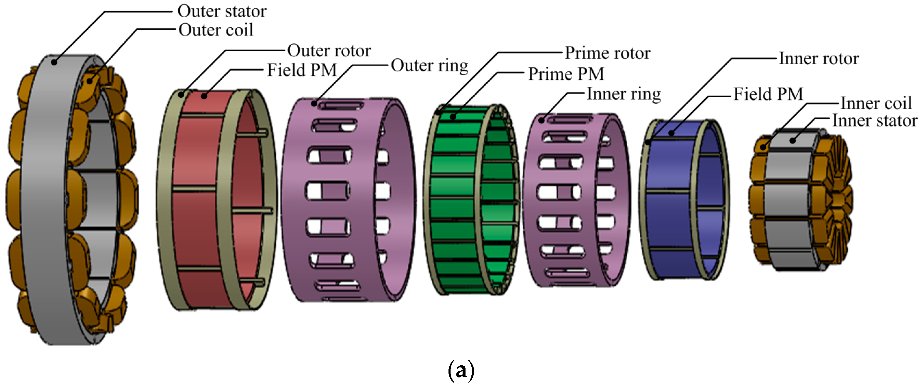
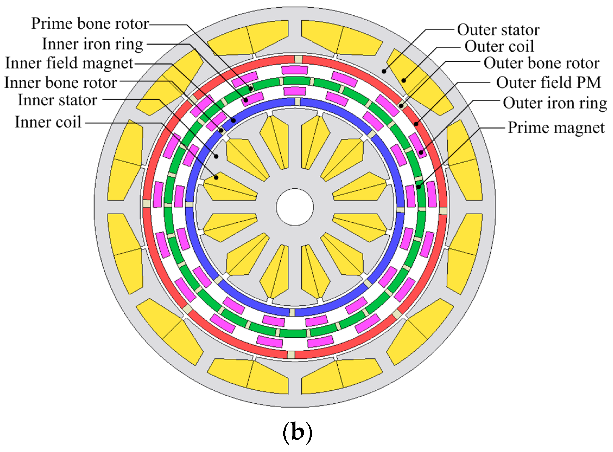
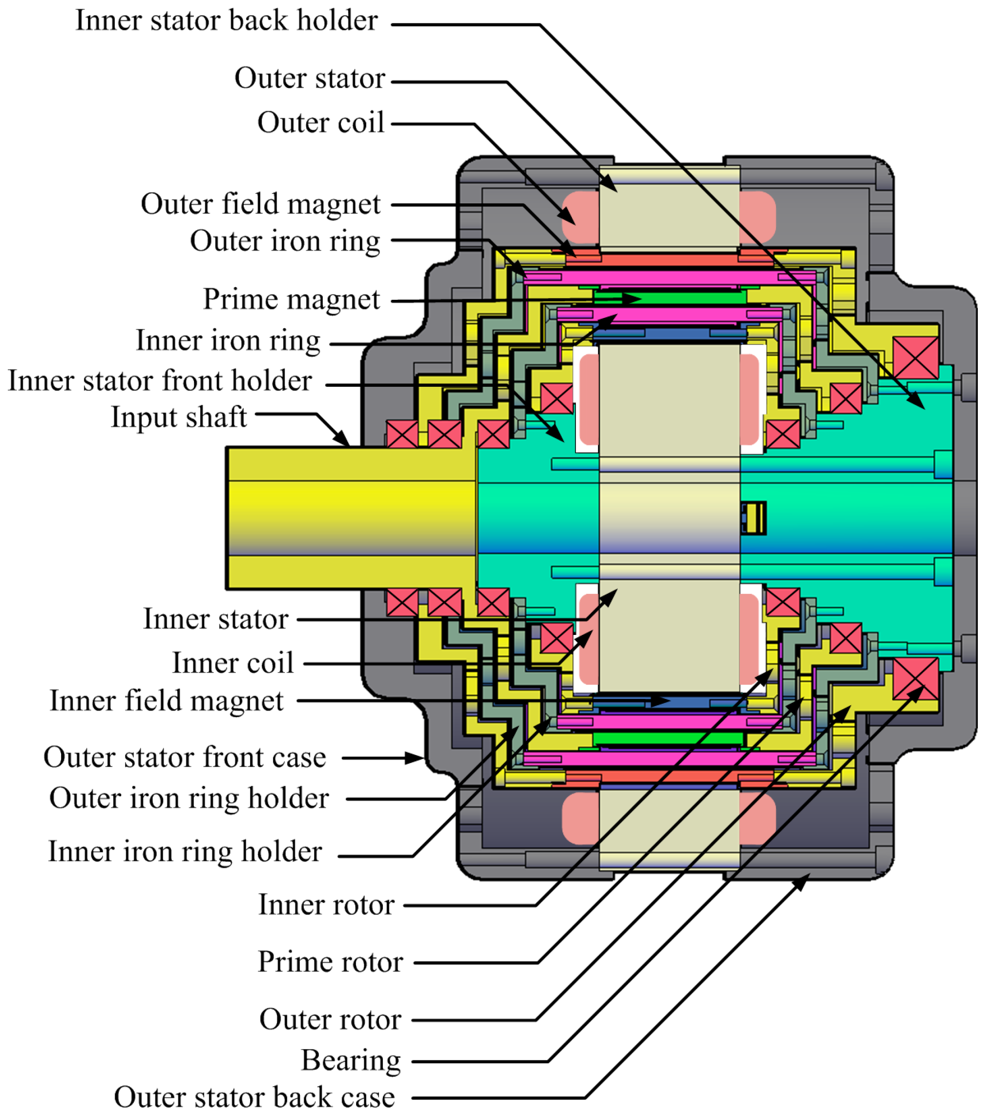
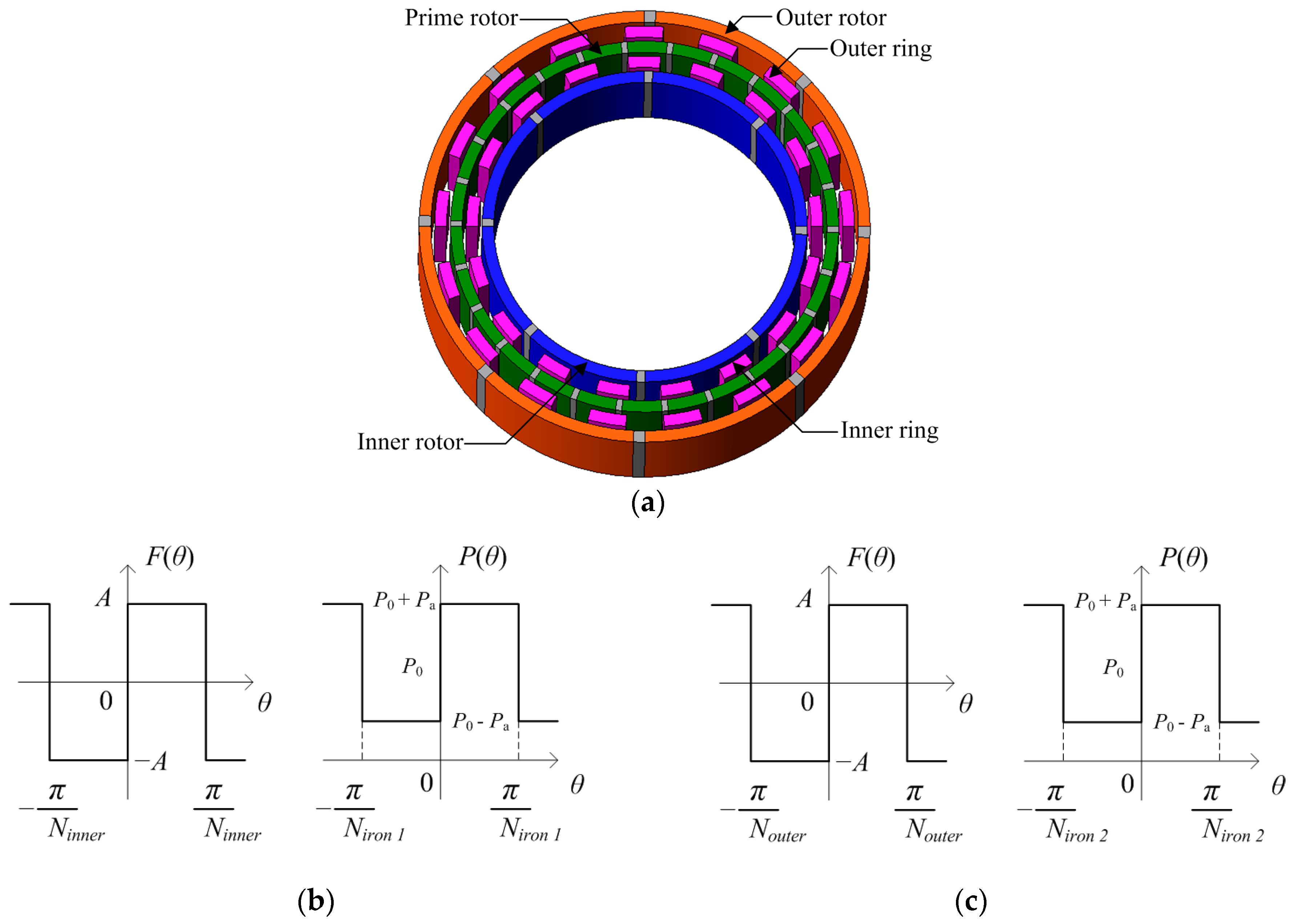
2. Proposed Structure and Machine Operating Principle

Figure 1 shows the structure of the proposed double-stator magnetic geared machine while the parameters are listed in Table 1. It is comprised of twelve parts. The outer field PMs, the outer modulating iron ring, the prime PMs, the inner modulating iron ring, and the inner field PMs are the active components that function as a magnetic gear. In the double-stator topology the two airgaps in the centre of the electrical machine are replaced with a magnetic gear. The proposed machine is designed in a magnetically coupled configuration with three bone rotors and three layers of mutual PMs. The advantage of the coupled configuration is the combined effect of the three PM rotors to the total flux-linkage in both outer and inner stators.
As illustrated in Figure 2, the prime PM rotor, which is the prime mover shaft for the magnetic gear, rotates at low-speed and is magnetically coupled simultaneously to both inner and outer field PM rotors. The high-speed field PM rotors and stators are interconnected through magnetic field excitation and this combination is equivalent to a conventional PM electrical machine. The output torque that is produced from the high-speed field PM rotor by the magnetic gear is due to the torque applied on the low-speed prime PM rotor. The material properties of the components used for the prototype machine are listed in Table 2, while the coil winding properties are listed in Table 3. A coaxial magnetic gear with three rotors is integrated with a double-stator PM machine to form a compact double-stator magnetic geared PM machine.

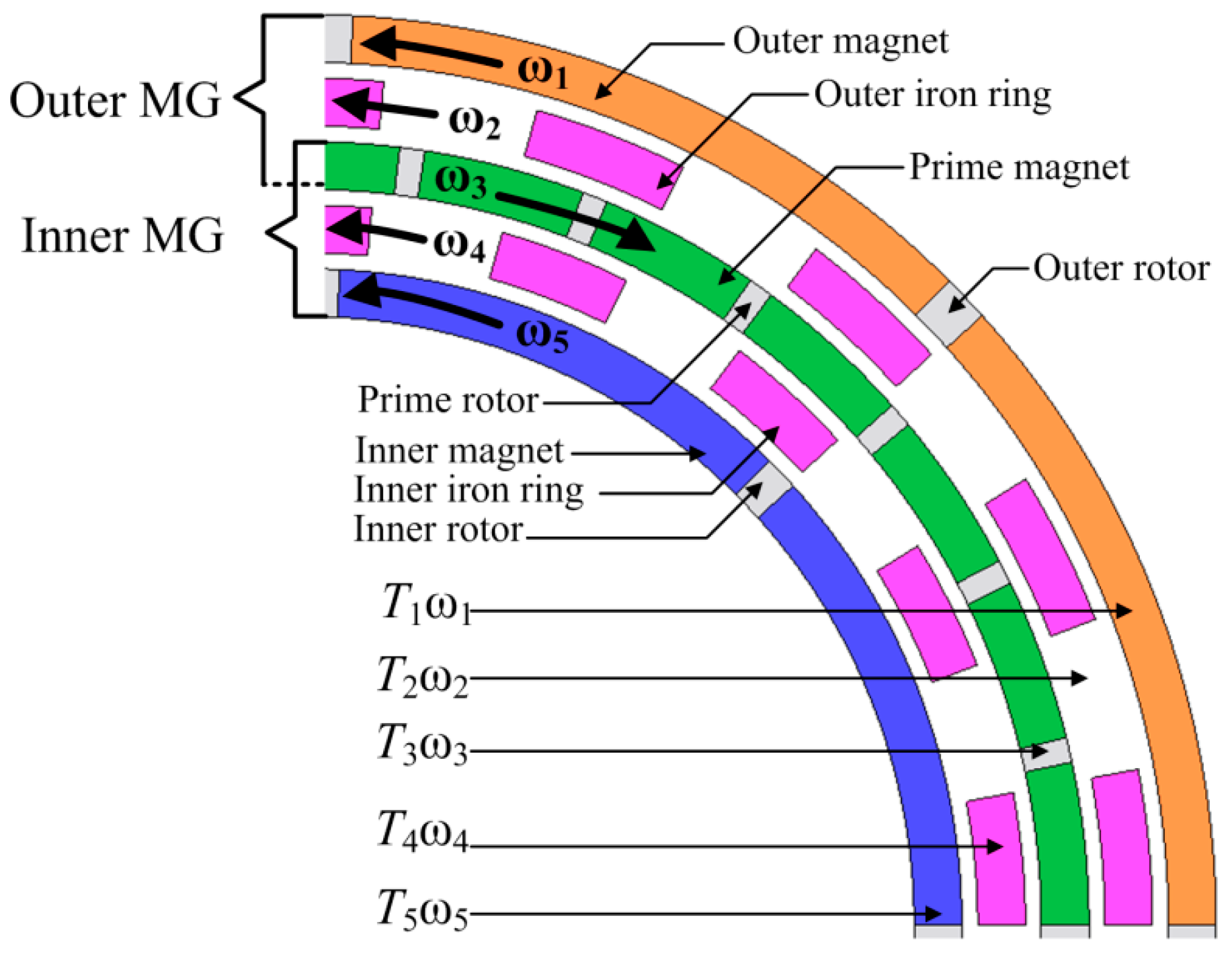
2.1. Triple Rotor Magnetic Gear Operating Principle

The operating principle of the triple rotor magnetic gear is based on the permeance difference between the air in the slots and the two iron rings [20]. The structure shown in Figure 3a consists of two magnetic gears with one low-speed rotor rotating two high-speed rotors simultaneously. The inner permanent magnet of the inner gear generates a magnetomotive force distribution, as shown in Figure 3b, while the inner iron ring generates a permeance distribution to vary the permeance, shown in Figure 3c.
The Fourier series expansions of F(θ) and P(θ) can be expressed by Equations (1) and (2):
F ( θ ) = m = 1 a m   s i n { ( 2 m 1 ) N i n n e r θ }
P ( θ ) = P 0 + n = 1 a n s i n { ( 2 n 1 ) N i r o n θ }
where Ninner is the inner rotor pole-pair number, Niron is the number of stationary iron ring pieces, am and an are the amplitude of the magnetomotive force and permeance, respectively, while P0 is the permeance of the iron ring pole pieces.
The magnetic flux distribution ϕ (θ) can be derived as follows [20]:
ϕ ( θ ) = F ( θ ) · P ( θ ) = m = 1 P o   a m s i n { ( 2 m 1 ) N i n n e r θ } + m = 1 n = 1 a m a n 2 [ c o s { ( 2 n 1 ) N i r o n ( 2 m 1 ) N i n n e r } θ c o s { ( 2 n 1 ) N i r o n + ( 2 m 1 ) N i n n e r } θ ]
The magnetic flux density distribution ϕ (θ) contains the H1(m), H2(n), H3(m,n), and H4(m,n) order constituents, which are shown in:
{ H 1 ( m ) = ( 2 m 1 ) N i n n e r H 2 ( m ) = ( 2 n 1 ) N i r o n H 3 ( m , n ) = ( 2 n 1 ) N i r o n ( 2 m 1 ) N i n n e r H 4 ( m , n ) = ( 2 n 1 ) N i r o n + ( 2 m 1 ) N i n n e r }
ϕ Δ t ( θ ) = F Δ t ( θ ) · P Δ t ( θ ) = F ( θ ω i n n e r Δ t ) · P ( θ ω i r o n Δ t ) = m = 1 P o a m s i n { H 1 ( m ) ( θ ω i n n e r Δ t ) } + m = 1 n = 1 a m a n 2 [ c o s { H 3 ( m , n ) ( θ H 1 ( m ) ω i r o n H 2 ( m ) ω i n n e r H 3 ( m , n ) Δ t }   c o s { H 4 ( m , n ) ( θ H 1 ( m ) ω i r o n + H 2 ( m ) ω i n n e r H 4 ( m , n ) Δ t } ]
The magnetic flux constituents H1(m), H3(m,n), and H4(m,n) each rotate ωinner, (H1(m)ωironH2(m)ωinner)/H3(m,n) and (H1(m)ωiron + H2(m)ωinner)/H4(m,n), respectively. The number of pole-pairs in H3(m,n) and H4(m,n) should be equal to Nouter or Ninner. The relationship between Ninner, Niron, and Nouter can be expressed as follows:
( 2 n 1 ) N i r o n = N o u t e r ± ( 2 m 1 ) N i n n e r
( 2 n 1 ) N i r o n   ω i r o n = N o u t e r ω o u t e r ± ( 2 m 1 ) N i n n e r ω i n n e r
{ ω i n p u t = ω i n n e r   [ N i n n e r ] ω o u t p u t = ω o u t e r 1 = ω o u t e r 2   [ N o u t e r 1 = N o u t e r 2 ] ω f i x e d = ω i r o n   1 = ω i r o n   2 = 0   [ N i r o n   1 = N i r o n   2 ] }
N i r o n = N o u t e r + N i n n e r  
G r = ω i n p u t ω o u t p u t   1 = N i n n e r N o u t e r 1
G r = ω i n p u t ω o u t p u t   2 = N i n n e r N o u t e r 2

2.2. Transmission Torque

The structure of the triple rotor magnetic gear shown in Figure 4 comprises an outer rotor with p1 pole-pair permanent magnets (PMs) with an angular speed of ω1; an outer iron ring consisting of n2 ferromagnetic pole-pieces with an angular speed of ω2; a middle rotor containing p3 pole-pair prime PMs with an angular speed of ω3; an inner iron ring comprising n4 ferromagnetic pole pieces with an angular speed of ω4; and an inner rotor comprising p5 pole-pair PMs with an angular speed of ω5. Both outer and inner rotors rotate in the opposite direction to the prime rotor.
The transmission torque of the magnetic gear is governed by:
N i r o n   1 = P o u t e r + P p r i m e   [ Outer   magnetic   gear ]
N i r o n   2 = P i n n e r + P p r i m e   [ Inner   magnetic   gear ]
By using the Maxwell stress tensor to calculate the average magnetic torque developed in the outer airgap between the outer rotor and prime rotor, the average magnetic torque can be expressed as [3]:
T m _ o u t e r = L e f R o u t e r 2 μ 0 0 2 π B r _ o u t e r B θ _ o u t e r d θ
Similarly, the average magnetic torque developed in the inner airgap between the inner rotor and prime rotor can be expressed as [3]:
T m _ i n n e r = L e f R i n n e r 2 μ 0 0 2 π B r _ i n n e r B θ _ i n n e r d θ
where Lef is the active axial length of the magnetic gear, Br_outer and Bθ_outer are the radial and tangential flux densities in the outer airgap, Br_inner and Bθ_inner are the radial and tangential flux densities in the inner airgap, and Router and Rinner are the radii of the outer and inner airgaps, respectively. Applying the law of conservation of energy and neglecting power losses in the magnetic gear shown in Figure 4, this yields:
T 1 ω 1 +   T 2 ω 2 +   T 3 ω 3 +   T 4 ω 4 +   T 5 ω 5 = 0
where T1, T2, T3, T4, and T5 are the torques for the outer rotor, outer iron ring, prime rotor, inner iron ring, and inner rotor, respectively. If the two iron rings are stationary (ω2 = ω4 = 0), this yields:
T 1 ω 1 + T 3 ω 3 + T 5 ω 5 = 0  
If the outer and inner PM rotors rotate at a similar angular speed due to their equal gear ratio, i.e., ω1 = ω5, then substituting into Equation (17) gives:
T 1 ω 5 + T 3 ω 3 + T 5 ω 5 = 0
T 3 =   ω 5 ω 3   ( T 1 + T 5 )
The gear ratio Gr obtained from the ratio of the inner rotor speed and prime rotor speed is expressed as:
G r = ω 5 ω 3
The gear ratio is equal to the torque ratio, and the equation that relates the magnetic torques on the three PM rotors for the magnetic gear is expressed as:
T r = T 3 T 1 + T 5
where Tr is the transmission torque ratio for the three PM rotors, which is equal to Gr neglecting power losses.
If both outer and inner rotors are stationary, i.e., ω1 = ω5 = 0, applying the law of conservation of energy it yields:
T 2 ω 2 + T 3 ω 3 + T 4 ω 4 = 0
T 3 = ω 1 ω 3 ( n 2 p 3 n 2 ) ( T 2 + T 4 )
The magnetic torque relationship between the prime PM rotor, outer iron ring, and inner iron ring can be expressed as:
T 3 = ( p 3 n 2 ) ( T 2 + T 4 )
where p3 is the pole number of prime PMs, n2 is the outer iron ring, T2, T3 and T4 are the torques for the outer iron ring, prime rotor and inner iron ring respectively.

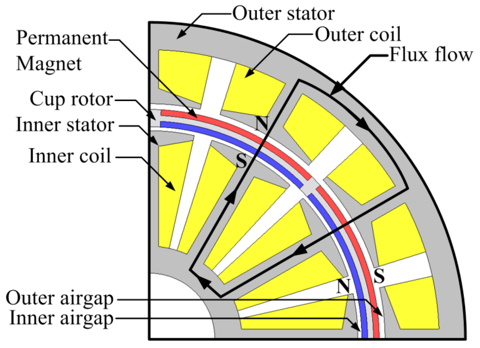
2.3. Double-Stator Permanent Magnet Machine Operating Principle

The output power of a double-stator permanent magnet machine (DS-PM machine) [21] produced by the inner stator can be expressed as:
P 1 = π 2 η K w A 1 B g 1 D g 1 2 L a ω r
while the output power produced by the outer stator can be expressed as:
P 2 = π 2 η K w A 2 B g 2 D g 2 2 L a ω r
The output torque produced from both the inner and outer airgap of a DS-PM machine [21] shown in Figure 5 can be calculated for the inner and outer stators. The torque produced by the inner stator in the inner airgap is derived as:
T 1 = π 2 η K w A 1 B g 1 D g 1 2 L a
Similarly the torque produced by the outer stator in the outer airgap is also derived as:
T 2 = π 2 η K w A 2 B g 2 D g 2 2 L a
The total output torque TTotal generated by the DS-PM machine is obtained by combining Equations (27) and (28) and can be expressed as:
T T o t a l = π 2 η K w B g ( A 1 D g 1 2 + A 2 D g 2 2 ) L a
where η is the efficiency, Kw is the winding factor, Bg is the magnetic loading, A1 and A2 are the electric loading of both outer and inner airgaps, respectively, Dg1 is the inner stator outer diameter, Dg2 is the outer stator inner diameter, La is the active axial length, and ωr is the rotor speed. In Figure 5 the flux flows radially from the magnet across the airgap, then circumferentially through the outer stator back yoke and returns across the airgap to the magnet to form a closed loop through the inner stator back yoke.

2.4. Cogging Torque Characteristics

The torque ripple results from the interaction of both field and prime PMs with the iron ring pole-pieces because there is variation in the reluctance of the air-gap between the iron rings and magnets. The torque ripple on the inner rotor varies with time and can be expressed as [3]:
T r i p p l e _ i n n e r =   n = 1 s n _ i n n e r s i n ( n A ( ω 1 t θ 1 ) )
where Sn_inner is the Fourier coefficient, A is the least common multiple of Ns and 2p1, Ns is the number of stationary pole-pieces, and p1 is the PM pole number. Also, the torque ripple on the outer rotor can be expressed as:
T r i p p l e _ o u t e r =   n = 1 s n _ o u t e r s i n ( n B ( ω 2 t θ 2 ) )
where Sn_outer is the Fourier coefficient, B is the least common multiple of Ns and 2p2, and p2 is the number of PM poles. Cogging torque in brushless PM machines is produced from the relationship between the magnets and stator tooth [22], which is expressed as:
T c o g = 1 2 ϕ g 2 d R d θ
where ϕ g is the air-gap flux, R is the reluctance of the air-gap, and θ is the mechanical angle of the rotor. The reluctance of the air-gap changes with periodicity; hence, it can be expressed in Fourier series as:
T c o g =   k = 1 T m k s i n ( m k θ )
where m is the least common multiple of stator slots number Ns and the pole number Np, Tmk is a Fourier coefficient, and k is an integer. For a magnetic gear [23], the smallest common multiple Nc between the number of PMs on the high-speed rotor and the number of iron pole pieces is expressed as:
C T = 2 p n s N c
where CT is the cogging torque factor and p is the pole number of PMs on the high-speed rotor. For PM brushless machines [24], the period of the cogging torque is expressed as:
N p = 2 p H C F ( Q , 2 p )
where Np is the number of periods of the cogging torque, Q is the number of stator slots, 2p is the number of poles, and HCF is the highest common factor between Q and 2p. The cogging torque factor for permanent magnet brushless machines [25], in general form, is given by:
C T = 2 p Q s N c
where Qs is the number of slots, 2p is the number of poles, and Nc is the smallest common multiple between Qs and 2p.

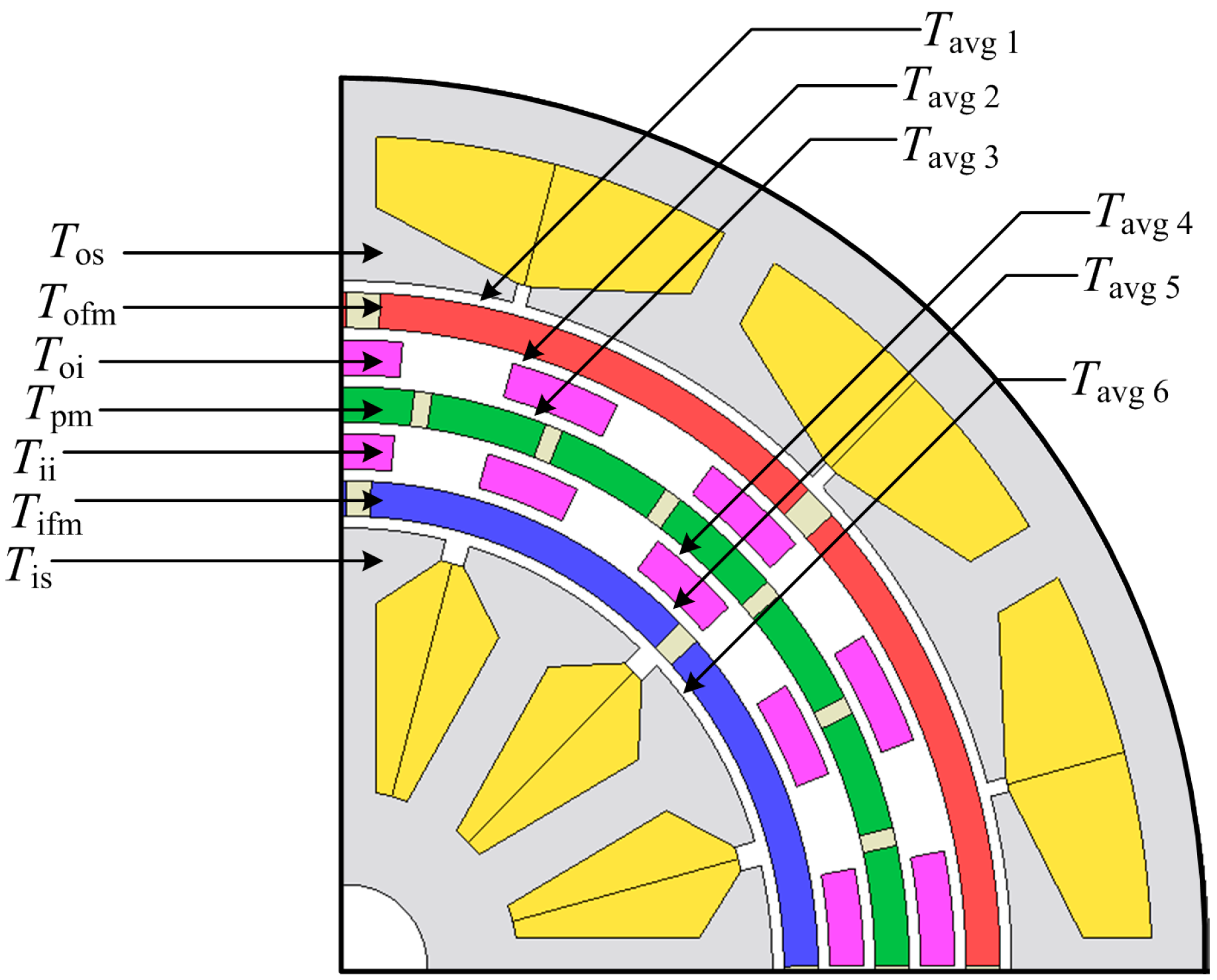
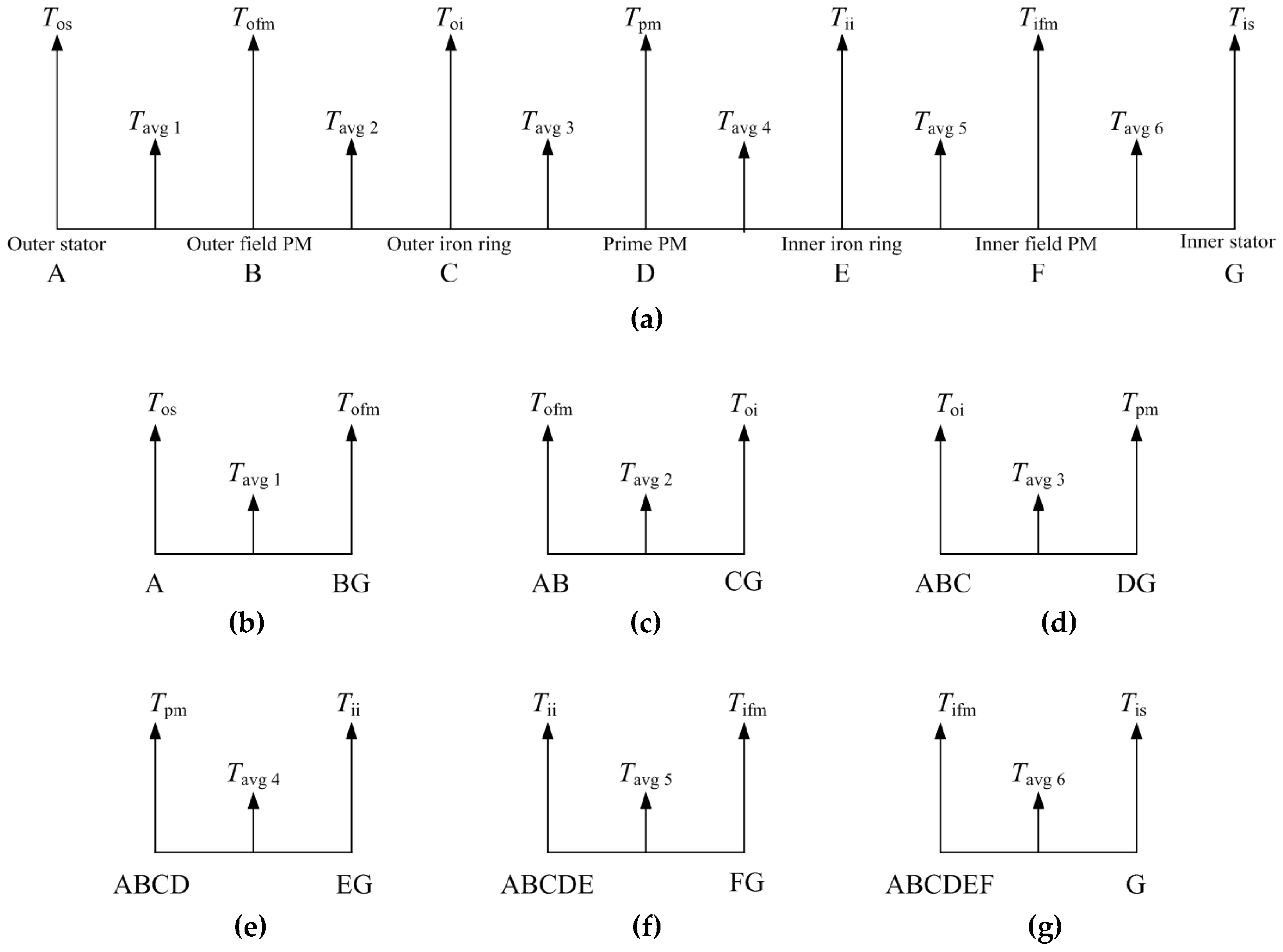
2.5. Torque Distribution Map and Analysis

The distribution of electromagnetic torque in the double-stator magnetic geared permanent magnet machine is difficult to investigate using analytical methods because of the machine’s complex structure. There are six airgaps with seven independent components; also, the stator iron yokes and bone rotors have nonlinear properties. The stationary iron ring pole pieces produce modulation effects, while the stator slots produce slot effects. In conventional magnetic gears, both outer and inner rotors consist of ferromagnetic iron yokes, while in the double-stator magnetic geared permanent magnet machine a stator replaces both outer and inner field PM rotors. We can assume the iron ring pole pieces to be equivalent to imaginary stator slots and the transmission torque on both outer and inner field PM rotors are affected simultaneously by the stators and stationary iron rings. The DS-MGM machine is analysed as a five-port machine consisting of three mechanical ports and two electrical ports. This section discusses the electromagnetic torque distribution on the whole machine. The electromagnetic torques generated by the outer stator, outer field PM rotor, outer iron ring, prime PM rotor, inner iron ring, inner field PM rotor, and inner stator are labelled Tos, Tofm, Toi, Tpm, Tii, Tifm, and Tis, respectively. When the machine operates in generator mode, both outer and inner stators output electrical power and can be expressed as:
P o s =   T o s ω o s
P i s =   T i s ω i s
where Pos and ωos are the mechanical power and angular speed of the outer stator, while Pis and ωis are the mechanical power and angular speed of the inner stator. The mechanical power generated by the inner field PM, outer field PM, and prime PM rotors, respectively, can be expressed as:
P o f m =   T o f m ω o f m
P p m =   T p m ω p m
P i f m =   T i f m ω i f m
where Pofm, Ppm, and Pifm are the mechanical power of the outer field PM, prime PM, and inner field PM rotors, respectively, while ωofm, ωpm, and ωifm are the angular speeds of the outer field PM, prime PM, and inner field PM rotors, respectively. The mechanical power generated by the inner and outer modulating iron rings can be expressed as:
P i i =   T i i ω i i
P o i =   T o i ω o i
where Pii and ωii are the mechanical power and angular speed of the inner iron ring, while Poi and ωoi are the mechanical power and angular speed of the outer iron ring. Neglecting all power losses and applying the law of conservation of energy, the torque sum of all five ports should be zero:
T o s ω o s + T o f m ω o f m +   T i i ω i i +   T p m ω p m +   T i f m ω i f m +   T o i ω o i + T i s ω i s = 0
T o s + T o f m +   T i i +   T p m +   T i f m +   T o i + T i s = 0
To illustrate the torque relations of Tos, Tofm, Toi, Tpm, Tii, Tifm, and Tis, a torque distribution map method is proposed and illustrated in Figure 6. Points A, B, C, D, E, F, and G, as shown in Figure 7, symbolize the outer stator, outer field PM rotor, outer iron ring, prime PM rotor, inner iron ring, inner field PM rotor, and inner stator, respectively. The distance line AB represents the torque relation between the outer stator and the outer field PM rotor, while the distance line BC indicates the torque relation between the outer field PM rotor and outer iron ring. According to the torque equilibrium principle, the relation between Tos and Tofm can be expressed as:
T o s =     T o f m
Based on Newton’s third Law, Tofm acts as counter-torque equal in value but in the opposite direction to Tos. This implies that for rotation of the outer field PM to occur the condition line BC > AB should be satisfied and the midpoints Tavg 1, Tavg 2 are assumed as pivot points representing the average electromagnetic torques for lines AB and BC, respectively. Line ABCDEFG acts as a lever balancing torque and the product sum of the electromagnetic torques is equal to zero, as stated in Equation (45). If midpoints Tavg 1, Tavg 2, Tavg 3, Tavg 4, Tavg 5, and Tavg 6 are selected as pivot points, a set of equations can be realized for each point to obtain:
T a v g   1 = A + B G 2
T a v g   2 = A B + C G 2
T a v g   3 = A B C + D G 2
T a v g   4 = A B C D + E G 2
T a v g   5 = A B C D E + F G 2
T a v g   6 = A B C D E F + G 2
where point A is the outer stator torque and point BG is the sum torques of the outer field PM rotor, outer iron ring, prime PM rotor, inner iron ring, inner field PM rotor, and inner stator, respectively. Similarly, the electromagnetic torque on the other points B, C, D, E, and F are the sum torques on each side of the pivot points. However, for the three PM rotors to rotate the following conditions should be satisfied:
{ T a v g   2 > T a v g   1   [ Torque   between   line   BC   greater   than   line   A B ] T a v g   3 > T a v g   2   [ Torque   between   line   C D   greater   than   line   B C ] T a v g   4 > T a v g   5   [ Torque   between   line   D E   greater   than   line   E F ] T a v g   5 > T a v g   6   [ Torque   between   line   E F   greater   than   line   F G ] }

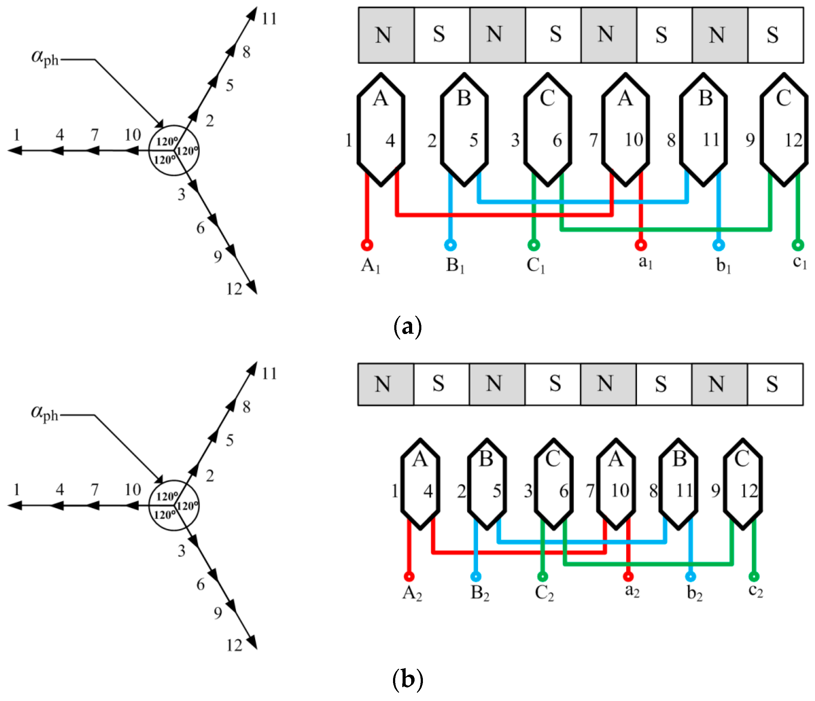
2.6. Stator Slots and Winding Design

The outer and inner stators are both designed with fractional slots and concentrated windings. Fractional slot windings have advantages over distributed windings because they reduce the end-winding lengths, torque ripple [26], coil volume and copper losses, machine axial length, and increased slot fill factor [27,28]. The calculated slot-per-phase-per-pole q = 1/2 and q < 1. Therefore, a double-layer concentrated winding scheme is adopted for both inner and outer stators, which have two coil sides per slot and separate phases. The slot-vector star method is used to determine the correct coil winding connections shown in Figure 8a,b. The key is to achieve the largest amplitude of the main harmonics in the induced EMF and achieve equal EMF waveform in the three phases. The machine periodicity t can be expressed as:
t = G C D { Q , p }
where GCD is the greatest common divisor, Q is the number of slots, and p is the number of poles. The number of spokes is Q/t, with t number of phasors in each spoke and the angle between two spokes is given as:
α p h = 2 π ( Q / t )
where αph is the electrical angle between two slots, which results in Q = 12, p = 4, t = 4, number of spokes = 3, and αph = 120°. There are four phasors per spoke, as shown in Figure 8a,b.

3. Finite Element Method

A two-dimensional finite element method is used to evaluate the electromagnetic characteristics of the double-stator magnetic geared PM machine. The two-dimensional electromagnetic field equation [29] of the proposed machine governed by Maxwell’s equation is given as:
Ω :   x ( v y x ) + y ( v y y ) = J v ( B r y x   B r x y ) + σ A t
where is the field solution region of calculation, A is the magnetic vector potential, J is the current density, v the is reluctivity, σ is the electrical conductivity, and Brx and Bry are the remanent flux density components. The back-electromagnetic force (Back-EMF) of the stator coils can be expressed as:
e =   L S ( Ω + A t d Ω Ω + A t d Ω )
where e is the Back-EMF generated by one coil, L the axial length of the machine, S is the area of conductor of each phase winding, and Ω+ and − are the cross-sectional areas of the input and output conductor coil, respectively. The circuit equation of the machine in motoring mode is given by:
R i + L e d i d t + l S Ω A t d Ω = u
where R is the resistance per phase winding, Le is the inductance of the coil end windings, i is the phase current, l is the axial length, S is the area of each phase winding conductor, and is the total cross-sectional area of conductors of each phase winding. The circuit equation in generating mode is given by:
( R 0 + R ) i + ( L 0 + L ) d i d t l S Ω A t d Ω = 0
where R0 is the resistance per phase winding, R’ is the resistance of the load, L0 is the inductance of the coil end windings, and L’ is the inductance of the load. The general motion equation is given by:
J m d ω d t + B ω = T e m T L
where Jm is the moment of inertia, B is the coefficient of friction, ω is the mechanical speed, TL is the load torque, and Tem is the electromagnetic torque. The rotational motions of the prime PM rotor, inner PM rotor, and outer PM rotor are governed by:
J 1 d ω 1 d t + B 1 ω 1 = T 1 T L
J 2 d ω 2 d t + B 2 ω 2 = T e m T 2
J 3 d ω 3 d t + B 3 ω 3 = T 3 T L
where J1, J2, and J3 are the moments of inertia of the inner rotor, prime rotor, and outer rotor, respectively; T1, T2, and T3 are the torque of the inner rotor, prime rotor, and outer rotor, respectively; and ω1, ω2, and ω3 are the mechanical speeds of the inner PM rotor, prime PM rotor, and outer PM rotor, respectively.

4. Results and Discussion

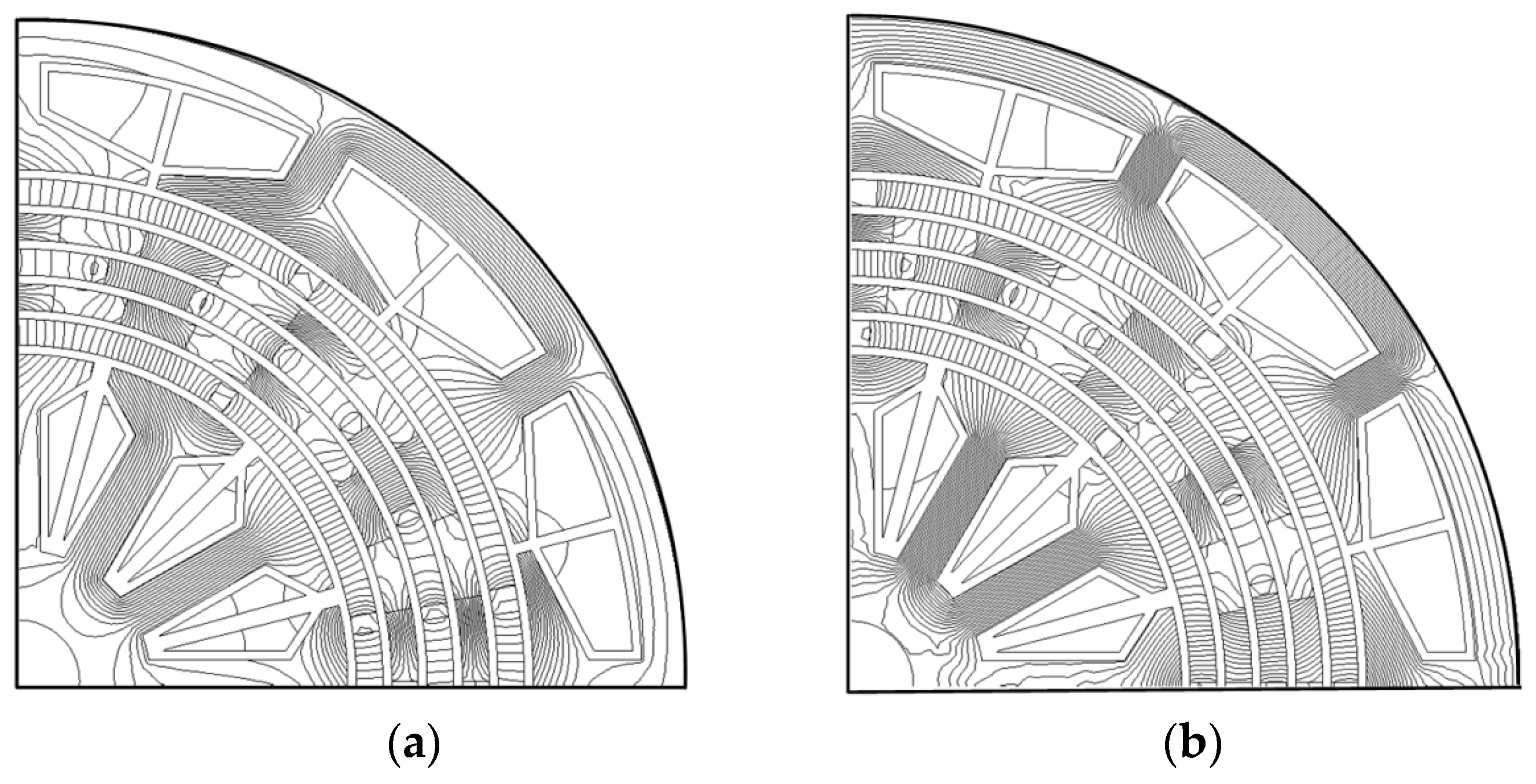
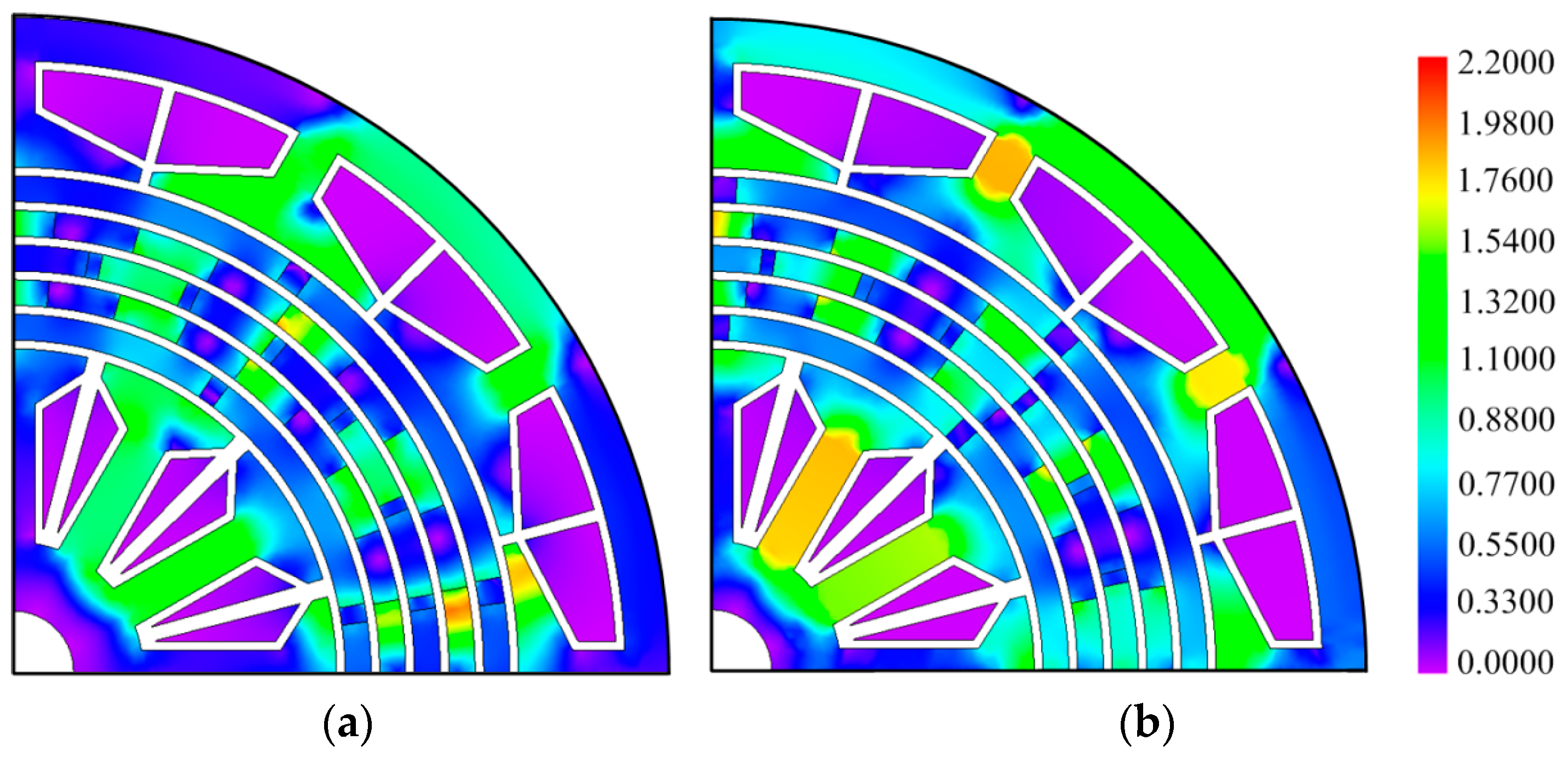
4.1. Flux Density Distribution

In Figure 9a there is reduced magnetic flux at no load and the flux flows across the air-gap with minimal flux fringing, while in Figure 9b the magnetic flux increases with load. Also, both the inner and outer field PMs have a pole-arc angle of 42° because in practice the full magnet pole-arc is rarely used due to manufacturing considerations and its effect on the cogging torque. In Figure 10b it is observed that the magnetic flux density is more saturated at the outer stator back iron and inner stator pole shoe compared to Figure 10a since the magnetic flux flows through the shortest back iron path of the magnetic circuit.

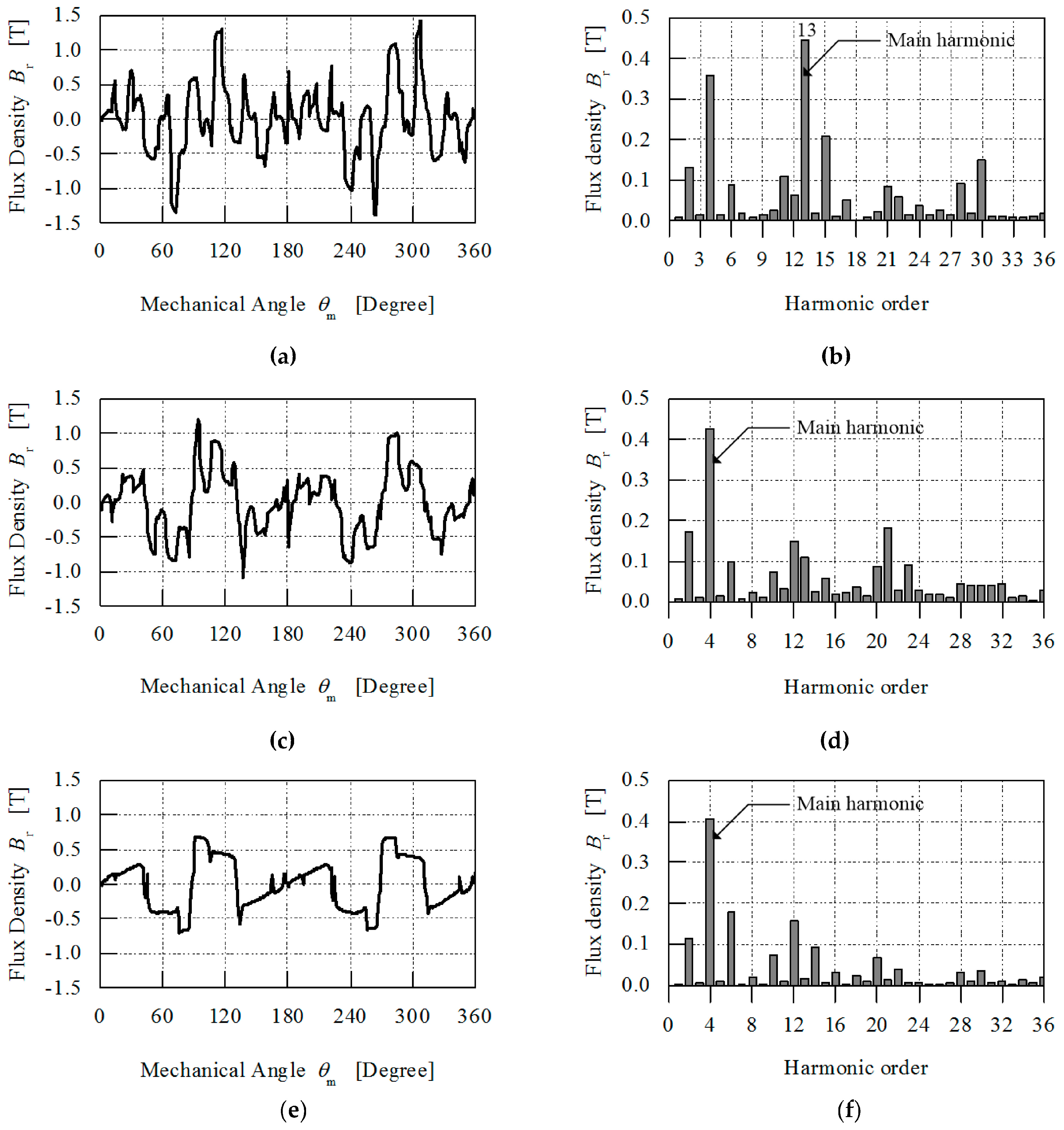
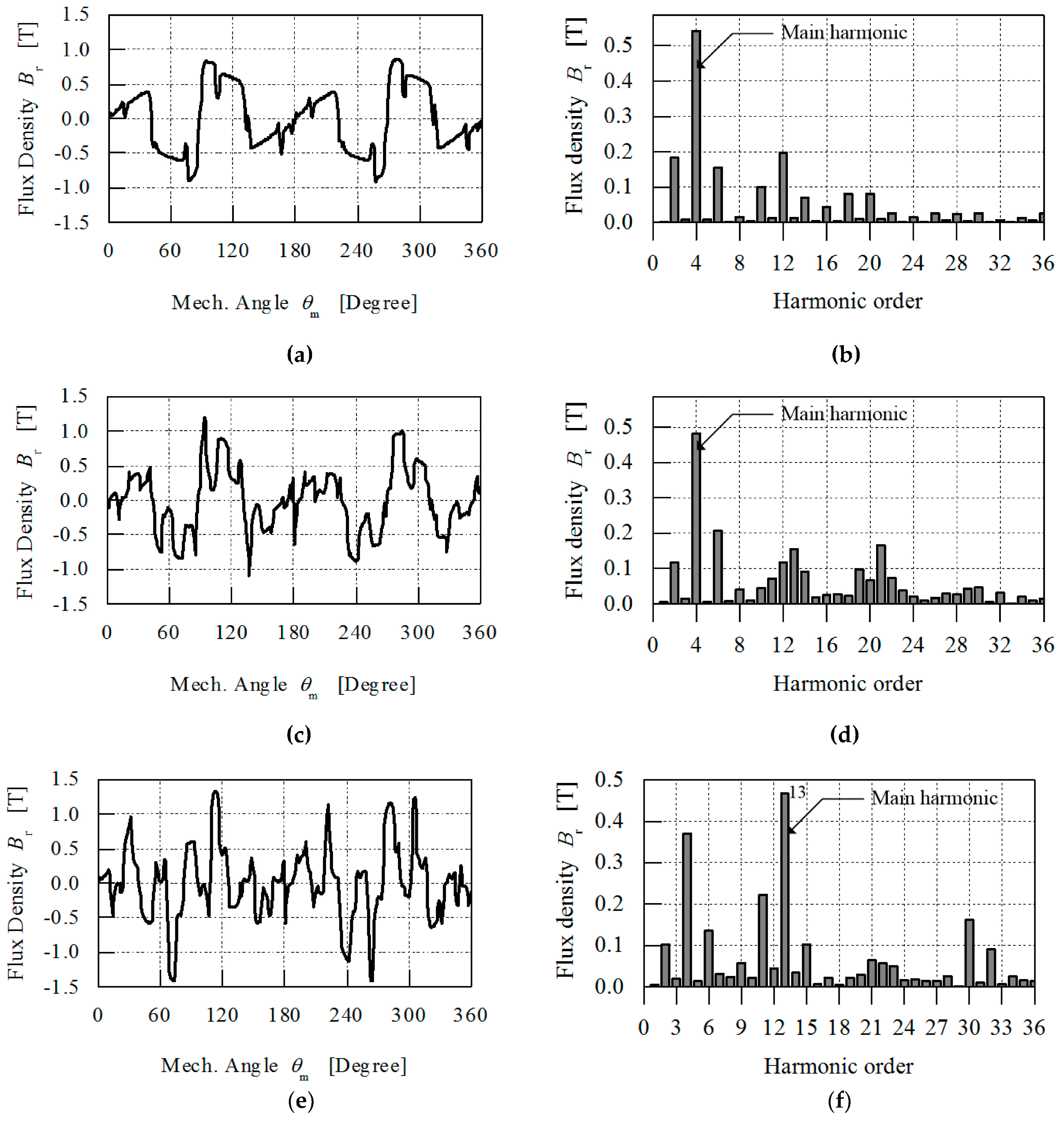
4.2. Flux Density Characteristics and Harmonic Analysis

The Fast Fourier Transform (FFT) was used for the harmonic spectrum analysis of the magnetic flux density at the centre of the magnetic gear’s three inner air-gaps. Figure 11a illustrates the radial component of the magnetic flux density between the inner field PMs and inner stator, while Figure 11b shows its harmonic order. The number of flux density pulsations is eight, which corresponds to the number of poles of field PMs. Also, the main harmonic number is four, equal to the field PMs pole-pair number. Figure 11c shows the radial component of the flux density at the centre of the air-gap between the prime PMs and inner iron ring, while Figure 11f shows the harmonic order.
The magnetic flux density at the centre of the three outer air-gaps is illustrated in Figure 12a,c,e, while their main harmonics are illustrated in Figure 12b,d,f. The effect of flux concentration between the prime PMs and outer iron ring shown in Figure 12c is dominant at 116°, 281°, and 306°, with 26 pulsations equal to 26 prime PMs (26 poles). In Figure 12c the flux density waveform between the outer field PMs and outer iron ring is concentrated at 94° and 279°, respectively. The ratio of main harmonics 4 and 13 is equal to 3.25, which confirms the calculated magnetic gear ratio of 3.25:1.

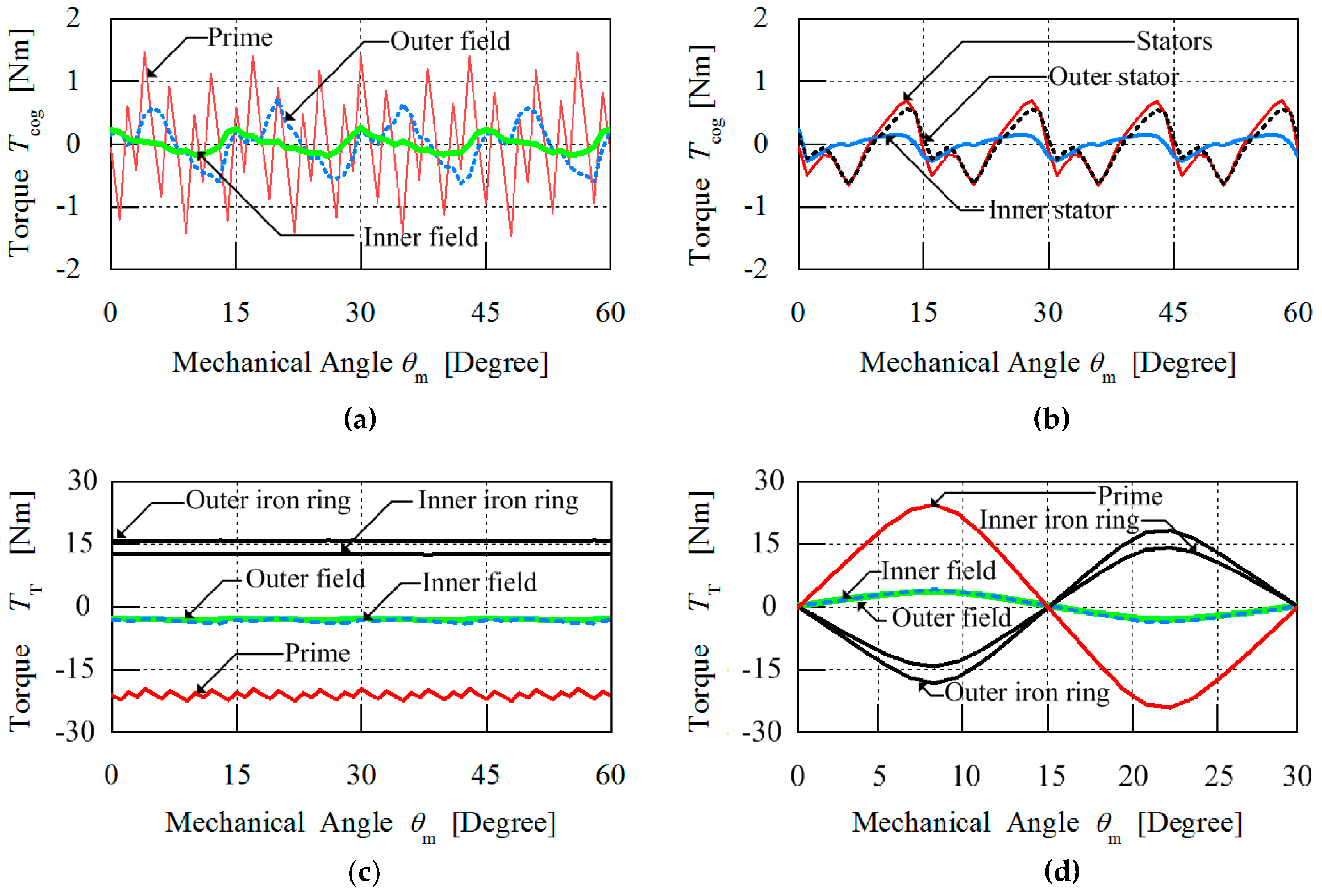
4.3. Cogging Torque and Transmission Torque Characteristics

Figure 13a illustrates the cogging torque of the inner field, outer field, and prime PM rotors in the magnetic gear; their calculated results are shown in Table 4. Also, Figure 13b shows the cogging torque from the stators. In Table 4 it is observed that the peak-to-peak cogging torque on the inner stator is 64% less than that on the outer stator. Figure 13c illustrates the average transmission torque of the outer field, inner field, and prime PM rotors in the magnetic gear; their computed results are shown in Table 5. The simulated transmission torque ratio is 3.25: 1, which is equal to the magnetic gear ratio. The maximum torque-angle curves of the three PM rotors shown in Figure 13d are calculated by holding the prime rotor static while both inner and outer rotors are rotated step by step. It can be observed that the torque-angle curve is sinusoidal and the maximum torque value indicates the pull-out torques. The maximum torque value is shown in Table 5 and the torque ratio calculated as 3.16 is 97% accurate with the calculated gear ratio of 3.25.
For the 3.25 : 1 magnetic geared machine, the lowest common multiple between the number of field PM poles 2p1 = 8, and the number of iron ring pole-pieces ns = 17, is 136 which is the value of the fundamental order of the ripple torque waveform. By substituting into Equation (34), a cogging torque factor of 1 is obtained. This means that if the lowest common multiple is greater than 1, a transmission torque with high torque ripple will be realised. As evident in Figure 14a,c,e, the prime rotor, inner rotor, and outer rotor exhibit low torque ripple in their transmission torque. Figure 14b,d,f shows the harmonic analysis of the ripple torque and it can be seen that the sixth-order ripple torque harmonic is prominent, which is caused by the flux-linkage of the coil winding flux with the magnetic flux generated by both outer and inner field PMs. The flux-linkage has harmonic components but the prime PMs are in a magnetically coupled configuration with both outer and inner field PMs and therefore the sixth-order ripple torque harmonic also appears in the prime rotor ripple torque. The sixth-order ripple torque harmonic can be reduced by optimisation of the stator teeth geometry. Also the 12th and 34th order ripple torque harmonics are clearly visible in Figure 14d, this demonstrates that both orders are multiples of 12 stator slots and 17 iron ring pole pieces containing harmonic components.

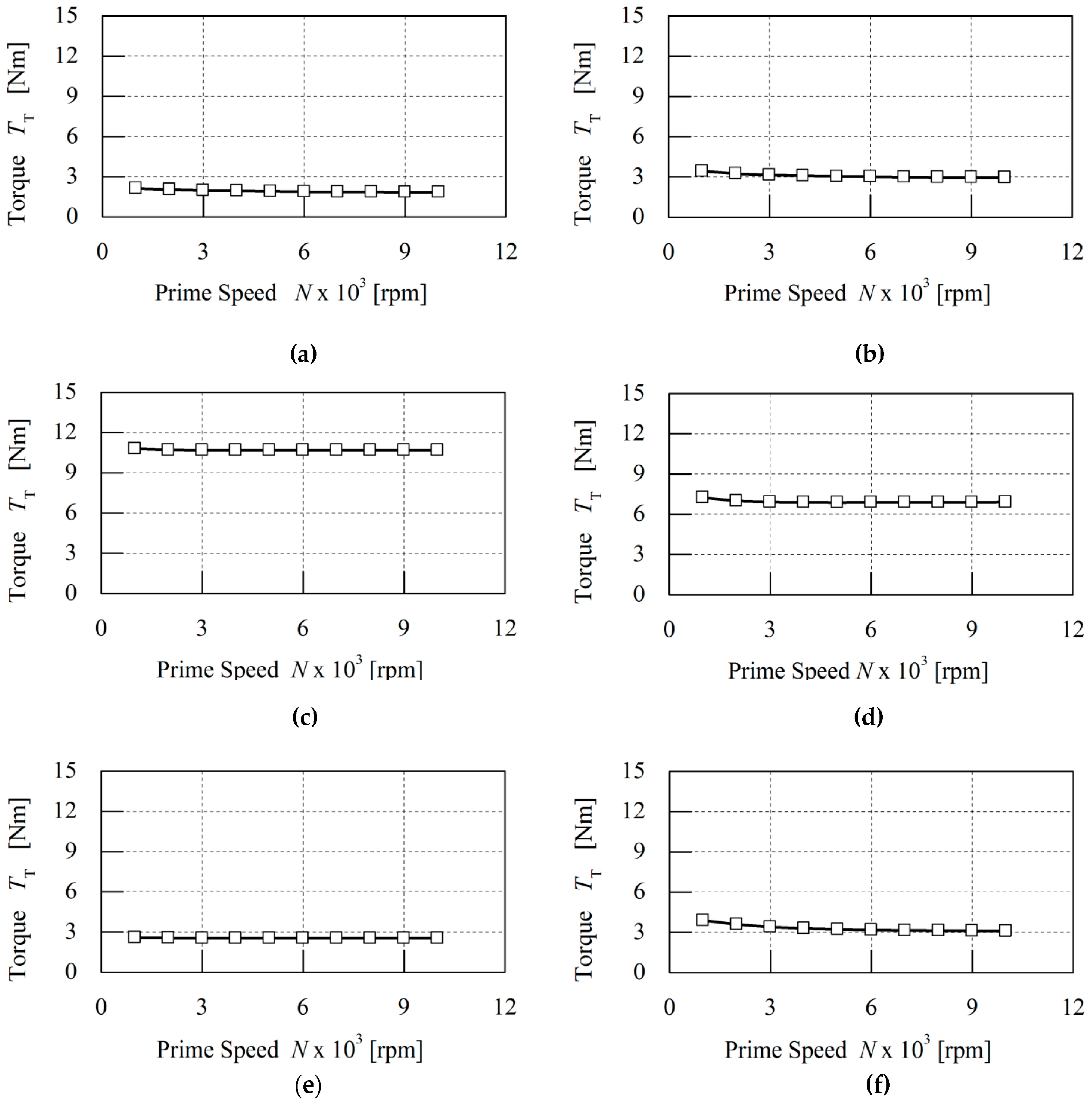
4.4. Torque Distribution Characteristics

The torque characteristics shown in Figure 15 without load and Figure 16 with load indicate that there is a linear relationship between the machine’s torque and the rotational speed of the prime mover. For the analysis of the torque distribution, the slope of the line known as the torque–speed constant, kslope, is chosen as the evaluating parameter, which is similar to the power–speed constant [30]. The torque-speed constant is calculated by finding the slope of the average torque distribution between two parts when operating at different speeds. The kslope is calculated by Equation (64):
k s l o p e = T a v g   2 T a v g   1 ω 2 ω 1   ( Nm / rpm ) .
Table 6 and Table 7 shows the distribution torque speed constants at no load and with load between the seven parts of the machine.
The torque distribution characteristics without load between the outer stator and outer field PM shown in Figure 15a are similar to the torque distribution between the inner stator and inner field PM. At a prime rotor speed of 300 rpm maximum torque is achieved and the line curve dips slightly at speeds greater than 1000 rpm. The torque distribution between the prime PM and outer iron ring illustrated in Figure 15c,d is greater than the torque between the inner field PM and inner iron ring because the prime rotor has twenty-six poles of prime PMs compared to the eight poles of field PMs. Also, the magnetically coupled configuration confirms that the torque generated by the low-speed prime PM rotor is greater than the torque on the high-speed PM rotors. It can be observed that, as angular speed increases, the transmission torque reduces as a result of eddy current losses from the PMs and iron losses in the stationary iron rings. In Figure 15f the distribution torque between the inner stator and inner field PM uniform acts as a counter torque against the torque between inner iron ring and inner field PM shown in Figure 15e.
The torque distribution with load between the outer stator and outer field PMs as shown in Figure 16a reduces as a result of the counter torque force generated in the airgap. The fields’ PMs generate excitation current in the coils, resulting in a magnetic field that produces reaction torque on the stator. By applying the principles of Lentz’s law and Newton’s third law of motion, the magnetic torque reacts against the torque that rotates the prime PM rotor. The torque distribution analysis shows that the torque between the outer stator and outer field PMs is greater than that between the field PMs and iron ring. Also, the magnetically coupled configuration confirms that integration of magnetic gearing with PM machines produces torque distribution in the airgaps between each component of the machine. Also, it can be observed in Figure 16c,d that the torque between the prime PMs and iron ring is reduced due to the effect of the counter torque generated in the airgap between the field PMs and iron ring.

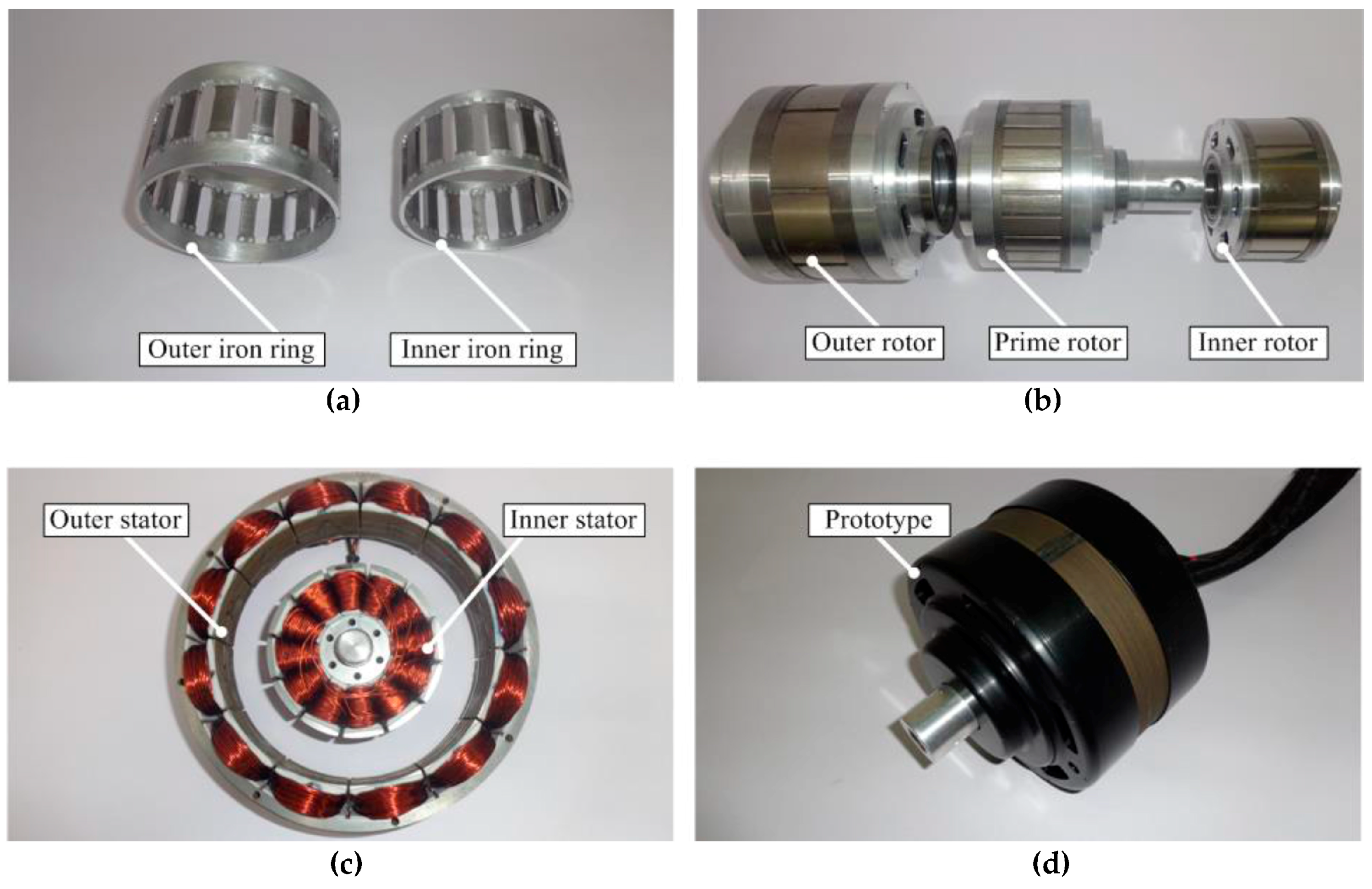
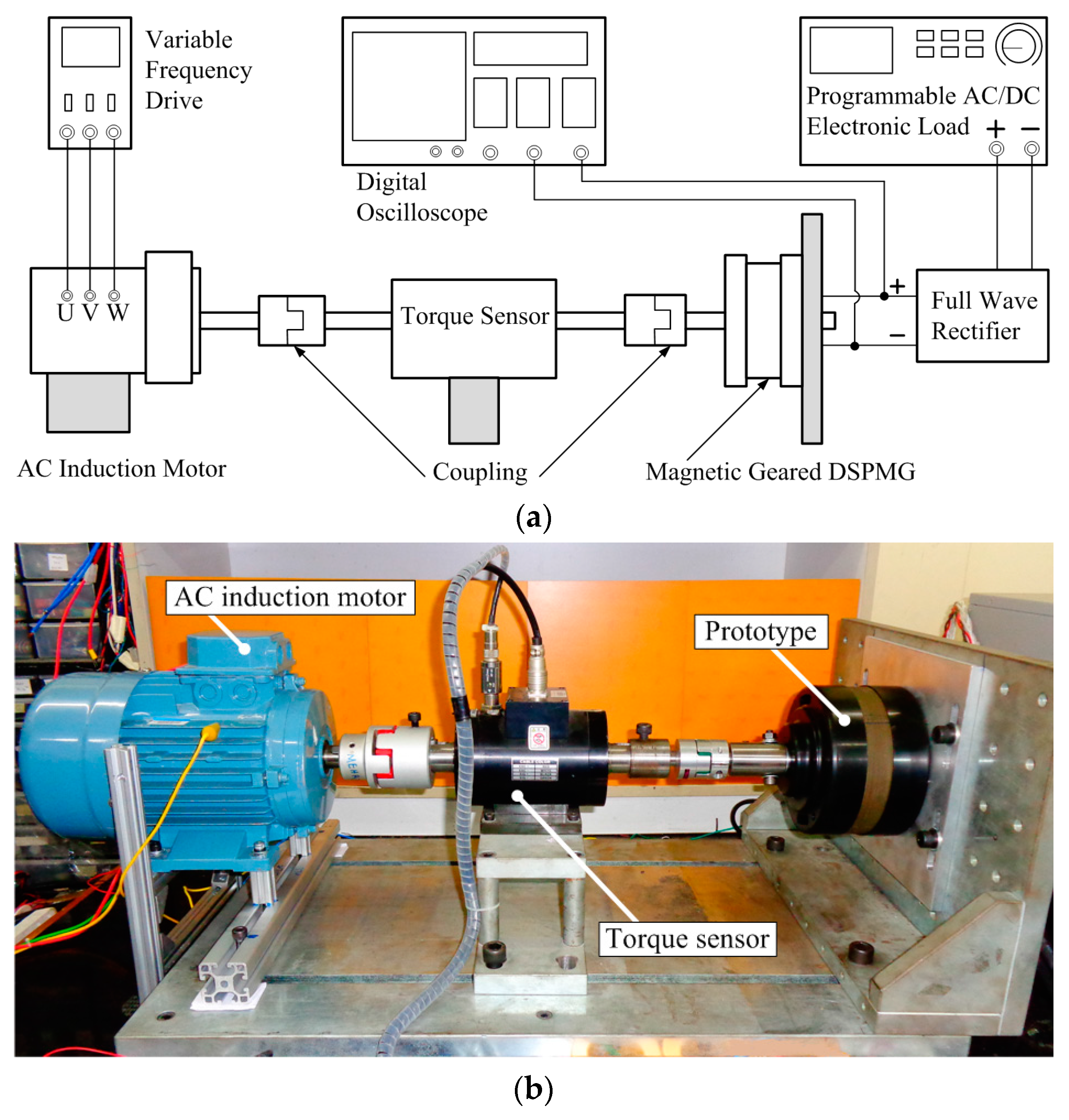
4.5. Prototype Machine

Figure 17 illustrates the fabricated components of the proposed machine, including the assembled prototype. The mechanical assembly of the DS-MGM is quite complex because all three PM rotors rotate separately and both modulating iron rings have to be fixed between the three rotors with an airgap of 1 mm. The bone rotor structure is used in designing the three rotors so that a magnetically coupled configuration is achieved between the magnetic gear and double-stator PM machine. The two modulating iron ring pole pieces are fabricated from solid steel, while the connecting end rings are made from aluminium to avoid short-circuiting the magnetic flux; since the proposed machine is designed for low-speed operation, the effect of eddy current losses is ignored. Future work could investigate the effect of laminated iron rings on eddy current losses at high-speed operation. The input shaft is machined from aluminium to reduce weight and is coupled to only the prime rotor, which results in difficulties in measuring the transmission torque for both the outer PM rotor and the inner PM rotor. To address this problem, the angular speeds of the outer and inner rotors are calculated from their fundamental frequency by spectrum analysis of the back EMF voltage produced from both outer and inner stators. The power, torque, and angular speed characteristics of the prototype DS-MGM were measured with the test rig shown in Figure 18b to verify the measured results against the calculated results. An AC induction motor was coupled to the assembled prototype generator and a three-phase variable frequency drive was used to control the AC induction motor’s speed and torque by varying the input frequency. The output terminals of the prototype generator were connected to a three-phase full bridge rectifier, while the output DC voltage, DC current, and DC power was measured with a single-phase programmable electronic load.

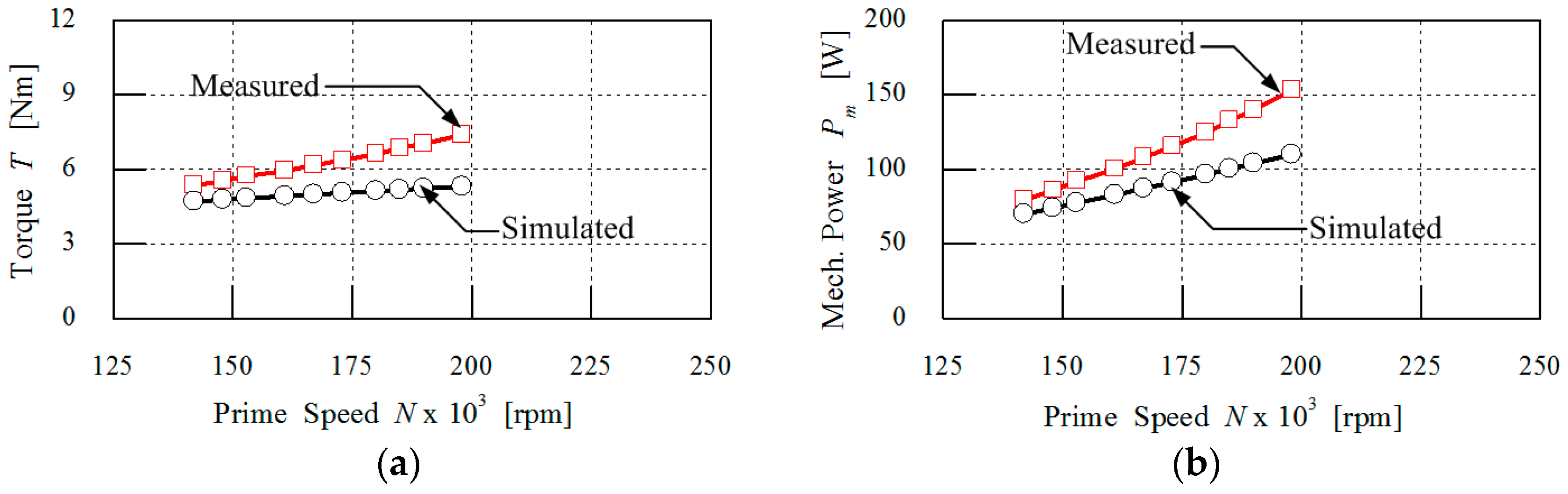
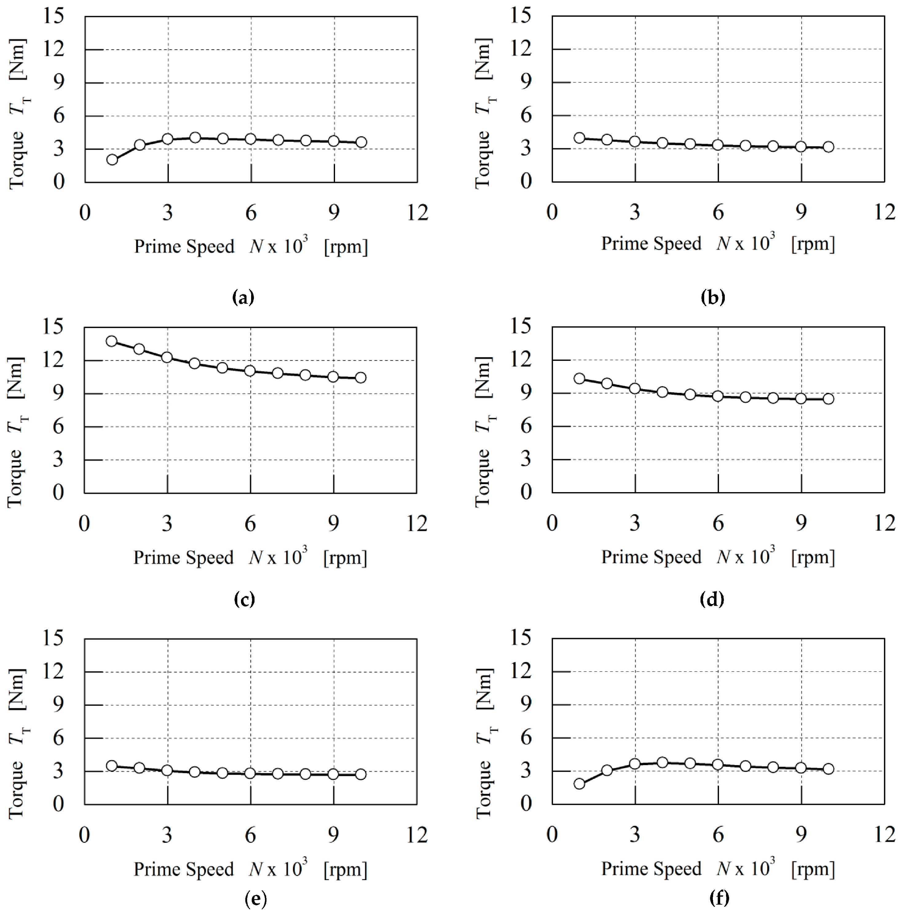
4.6. Mechanical Power–Speed Characteristics

The input mechanical power that rotates the prime rotor of the magnetic geared double-stator PM generator is calculated using Equation (65):
P m = 2 π n T 60   [ W ]
where Pm is the net mechanical power of the generator in W, T is the toque in Nm, and n is the rotational speed in rpm. The measured torque is obtained from the torque transducer shown in Figure 18b, while the calculated torque is obtained from 2D FEM. In the fabrication process of the prototype, initially the outer and inner iron rings are manufactured from solid steel to form a cage-like structure. A first experimental test was conducted on no-load and it was observed that the magnetic gear part of the generator slips when the speed of the prime PM rotor is greater than 110 rpm. An analysis of end effects indicates that magnetic flux leakage exists at the end rings due to circulating eddy currents in the pole pieces. To address this problem, the end connecting rings are designed from 3 mm thick aluminium, which is a non-ferromagnetic metal and magnetic flux barrier. Also, the aluminium end rings are connected with four steel rivet bolts per pole piece, or two rivet bolts for each end. The reason for using steel bolts was to achieve torsional strength for the iron rings against the reaction torques from both field PMs and prime PMs. Although laminated steel pole pieces bonded with epoxy and electrically insulated end rings may be an option for reducing eddy currents, but this increases the manufacturing costs and the difficulty of mechanical assembly. The second experimental test on no-load showed that the prime PM rotor achieved a speed of 700 rpm without the magnetic gear slipping. However, the effect of end connecting rings on transmission torque is not reported in the results because it is a subject for further study. Figure 19 shows the torque and mechanical power with a 100-ohm load and it is observed that the measured results are greater than the simulated values. It is likely caused by the following factors: first, the aluminium end connecting rings were secured to the pole pieces with steel bolts but the aluminium end rings are not electrically insulated from the steel bolts. This weak aspect results in induced eddy current produced by a time-varying magnetic field flowing around the iron rings and the eddy current exerts torque from the iron rings, therefore impacting the transmission torque between the prime PMs and field PMs. Secondly, end-effects are not accounted for in the two-dimensional finite element analysis of the magnetic geared machine; instead, the iron ring pole pieces are modelled as electrically insulated solid parts without end connecting rings. Ideally, the measured torque should be less than the simulated torque because friction and bearing losses are assumed to be insignificant in FEM analysis. These factors account for the large variation between the simulated torque and the measured torque.

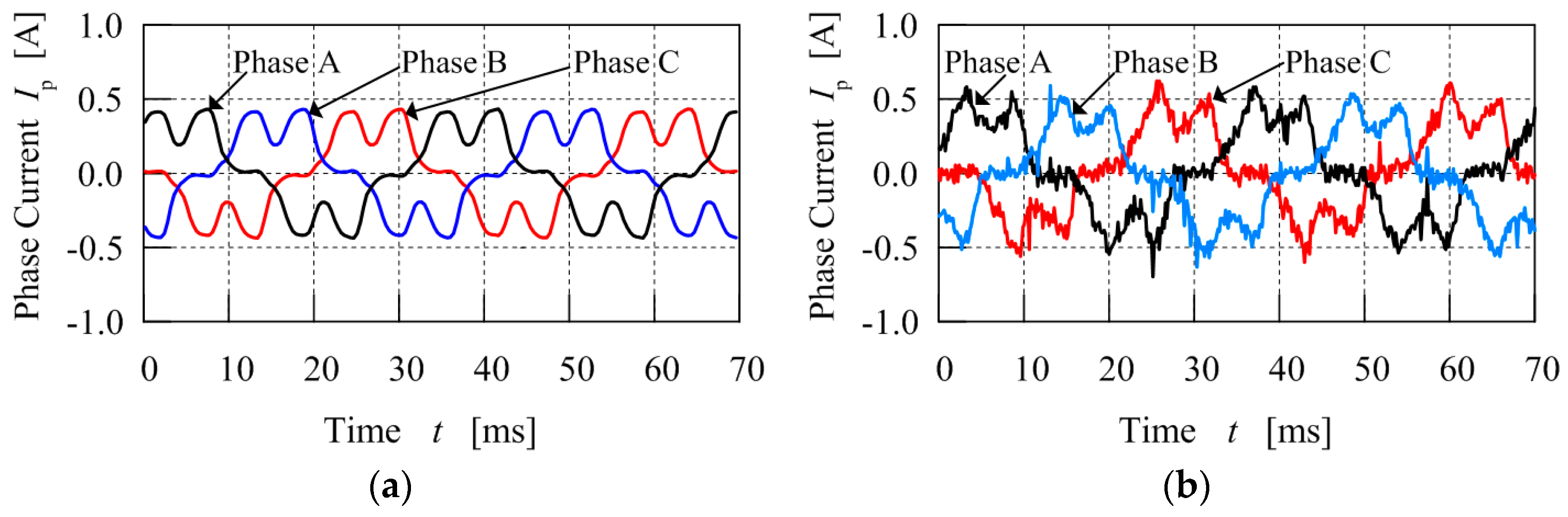
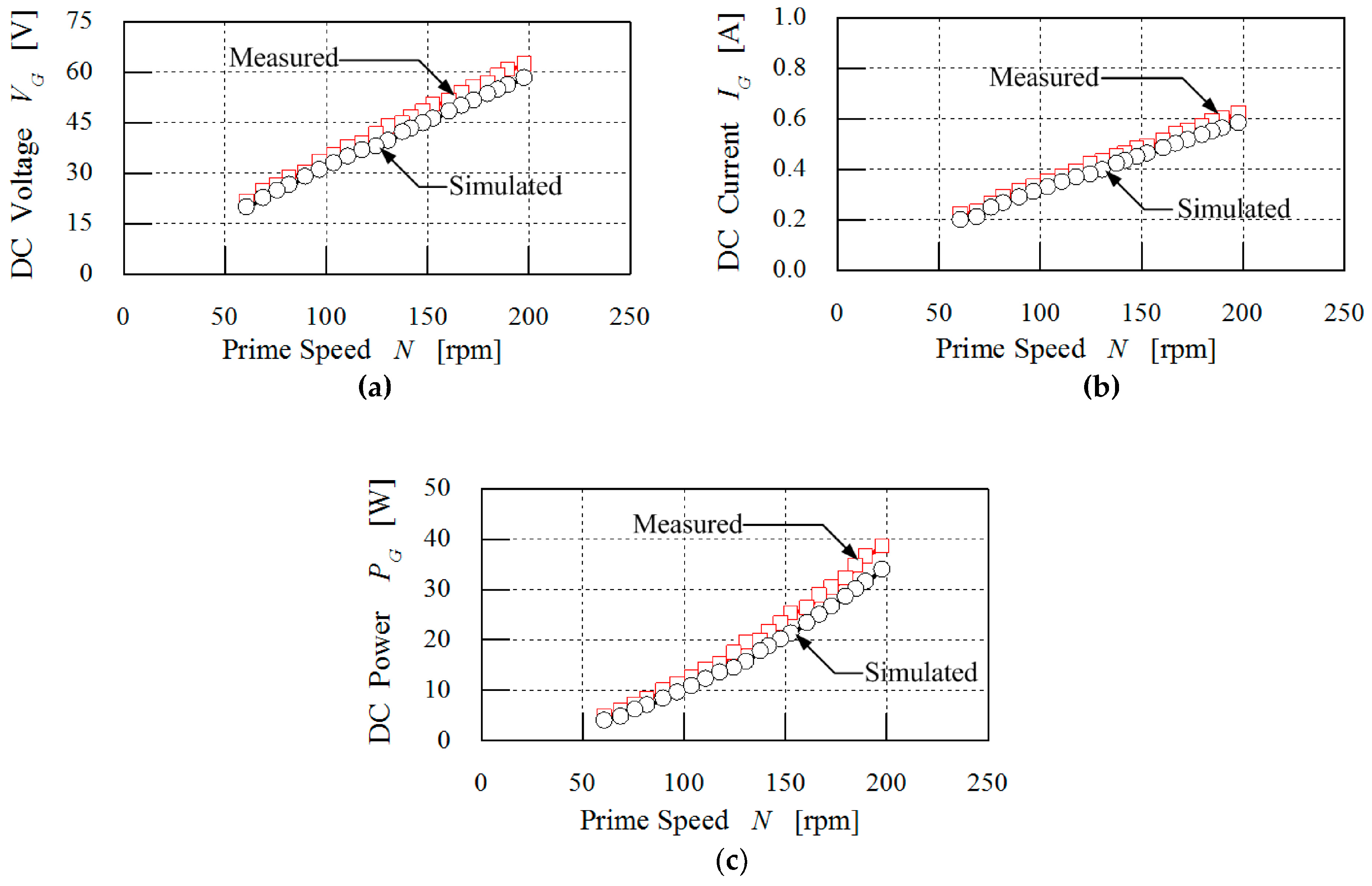
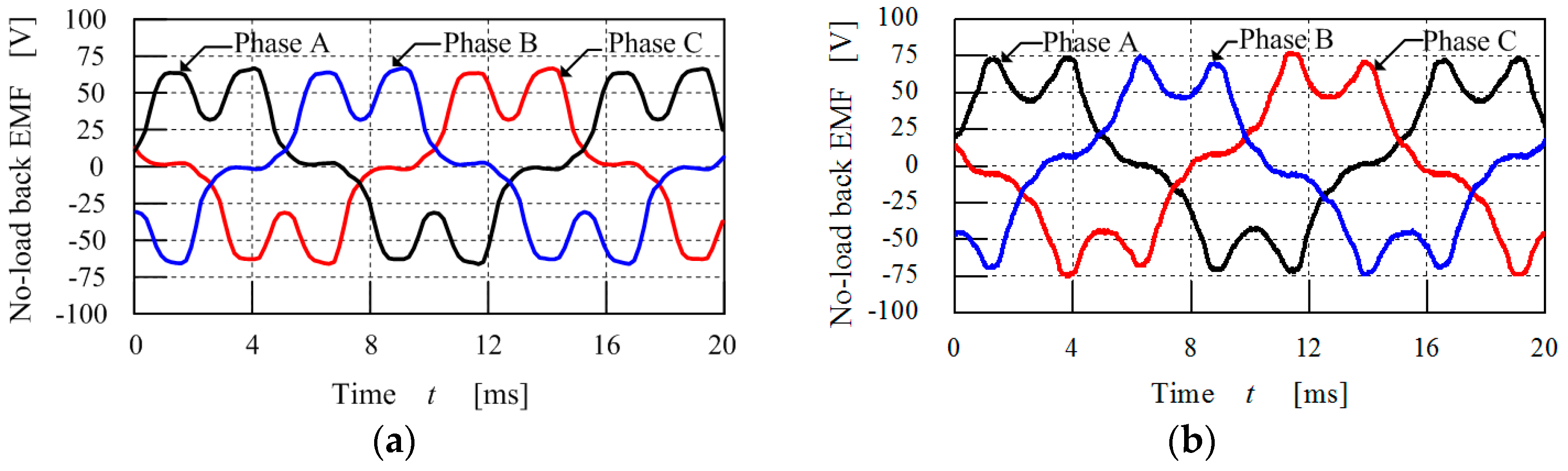
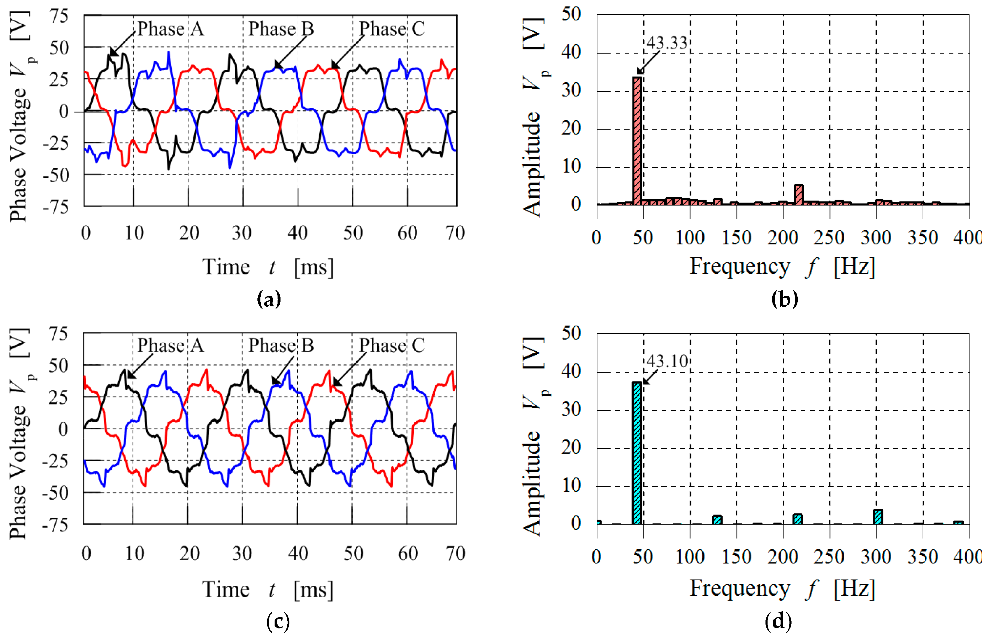
4.7. Electrical Power-Speed Characteristics

Figure 20 shows the calculated and measured no-load back EMF waveform at a prime rotor speed of 300 rpm. The induced peak-to-peak voltages from the calculated and measured results are 63 V and 75 V, respectively, for a double layer three-phase concentrated winding. It can be observed that both voltage waveforms match and are similar in output, which verifies the machine design. Although the induced voltage is not perfectly sinusoidal due to the presence of harmonics, these can be reduced by a proper selection of coil winding design. The measured voltage is greater than the simulated voltage by 19%; this difference could be caused by the effect of eddy current circulating between the iron ring pole pieces and aluminium end rings. The components are connected by steel rivet bolts and each iron ring pole piece would produce eddy currents; however, because the steel rivet bolts are not electrically insulated, a U-turn circuit is created by induced circulating eddy currents. This induced circulating eddy current produces a magnetic flux that can increase the back EMF. In the 2D FEM analysis these factors are not accounted for, which causes the simulated voltage to be less than the measured voltage. The use of non-electrically conductive material for the connecting end rings may be necessary to improve the accuracy of the measured results.
Figure 21 compares the simulated and measured three-phase voltage waveforms at the output of the generator before DC rectification on a load of 100 ohm at prime rotor speed = 200 rpm. The field rotor speed is calculated with the formula N = 120f/p by determining the frequency f from the three-phase voltage using spectrum analysis, which results in calculated and measured field rotor speeds of 650 rpm and 646 rpm, respectively. It can be seen that a good agreement exists between the simulated and measured voltage waveforms. Note that both waveforms are non-sinusoidal due to the existence of harmonic components, which is general for concentrated windings.
The simulated three-phase output current waveform before DC rectification with a 100-ohm load at a prime rotor speed of 200 rpm is shown in Figure 22 with the measured waveforms. It can be observed that both waveforms are non-sinusoidal due to the presence of the third harmonic generated by the concentrated winding configuration of the prototype machine. Also, the amplitude of the measured phase current waveform is greater than the simulated and this could be caused by eddy currents circulating between the iron ring pole pieces and aluminium end rings as both components are not electrically insulated, which results to an additional magnetic flux that causes a difference in the induced phase current. Even though the output three-phase current waveform is non-sinusoidal, the simulated and measured three-phase current waveforms are similar. The measured three-phase current waveform shown in Figure 22b is not smooth; this is mainly caused by the noise generated by the DC rectifier when the generator is connected to a resistance load. The DC full wave rectifier used in the measurement is built in-house and its quality may not be comparable to commercially available rectifiers, which have proper shielding from noise and adequate grounding.
The programmable AC/DC electronic load has limitations and can only simulate a single-phase load; for that reason, a DC full wave rectifier was connected between the generator and the load. The DC voltage characteristics are shown in Figure 23a when the external resistance load is set at 100 ohm and it is observed that the DC voltage graph demonstrates linearity while the measured DC voltage values agree closely with the calculated results. The measured DC current and DC power characteristics of the generator shown in Figure 23b,c are consistent with this observation. A comparison of the calculated and measured performance characteristics of the prototype is shown in Table 8. By applying the law of conservation of energy, it can be observed that the measured gear ratio is 0.61% less than the calculated gear ratio as a result of losses. Also, this observation is applicable to the reduced measured rotational speed of the field PM rotor. The measured DC voltage and power characteristics are greater than the simulated values by 1.12% and 0.99%, respectively, while the measured DC current is equal to the simulated value. The effect of circulating eddy currents from the aluminium end rings and iron rings before DC rectification also affects the variation between the calculated and measured DC power characteristics.

5. Conclusions

This paper has presented a novel magnetic geared double-stator PM generator and the torque distribution characteristics were studied using two-dimensional finite element analysis. Also, the power and speed characteristics were measured by the fabrication of a prototype. The torque distribution analysis shows that the magnetically coupled configuration between the three permanent magnet rotors affects the transmission torque of the magnetic gear. This can be observed in the large variation between the calculated and measured torque as a result of induced circulating eddy currents from the aluminium connecting end rings through the steel rivet bolts to the pole pieces. Although both stator slots and iron ring pole pieces equally affect the torque distribution, the torque between the field permanent magnets and the iron rings should be greater than the reaction torque between the stators and field PMs for the magnetic gear to rotate. A good agreement exists between the calculated and measured field PM rotor speed, DC voltage, DC current, and DC power characteristics. The torque distribution analysis shows that more power could be generated at a prime rotor speed greater than 1000 rpm if the transmission torque is optimised. However, the prototype could not be operated up to a prime rotor speed of 1000 rpm compared to the simulation model because of mechanical problems from the bearings, heat generation on the prime mover shaft, and manufacturing imperfections in the assembly. These problems will be addressed in future work to improve the efficiency of the generator.

Acknowledgments

The authors would like to express their gratitude to Ministry of Science, Technology and Innovation Malaysia for financial support and Universiti Putra Malaysia for the facilities provided during this research work.

Author Contributions

All authors contributed to this work by collaboration. Shehu Salihu Mustafa is the main author of this manuscript. Norhisam Misron assisted to perform the simulations and design the experiments. Norman Mariun, Mohammad Lutfi Othman and Tsuyoshi Hanamoto provided some very useful suggestions in the production of the paper. All authors revised and approved the publication of the paper.

Conflicts of Interest

The authors declare no conflict of interest.

References

  1. Li, X.; Chau, K.T.; Cheng, M.; Hua, W. Comparison of magnetic-geared permanent magnet machines. Prog. Electromagn. Res. 2013, 133, 177–198. [Google Scholar] [CrossRef]
  2. Rens, J.; Atallah, K.; Calverley, S.D.; Howe, D. A novel magnetic harmonic gear. IEEE Trans. Ind. Appl. 2010, 46, 206–212. [Google Scholar] [CrossRef]
  3. Jian, L.N.; Chau, K.T. A coaxial magnetic gear with halbach permanent-magnet arrays. IEEE Trans. Energy Convers. 2010, 25, 319–328. [Google Scholar] [CrossRef] [Green Version]
  4. Zhang, X.; Liu, X.; Wang, C.; Chen, Z. Analysis and design optimization of a coaxial surface-mounted permanent-magnet magnetic gear. Energies 2014, 7, 8535–8553. [Google Scholar] [CrossRef]
  5. Atallah, K.; Wang, J.; Mezani, S.; Howe, D. A novel high-performance linear magnetic gear. IEEJ Trans. Ind. Appl. 2006, 126, 1352–1356. [Google Scholar] [CrossRef]
  6. Mezani, S.; Atallah, K.; Howe, D. A high-performance axial-field magnetic gear. J. Appl. Phys. 2006, 99, 08R303. [Google Scholar] [CrossRef]
  7. Acharya, V.M.; Bird, J.Z.; Calvin, M. Flux focusing axial magnetic gear. IEEE Trans. Magn. 2013, 49, 4092–4095. [Google Scholar] [CrossRef]
  8. Jorgensen, F.; Andersen, T.; Rasmussen, P. The cycloid permanent magnetic gear. Trans. Ind. Appl. 2008, 44, 1659–1665. [Google Scholar]
  9. Niguchi, N.; Hirata, K. Transmission torque analysis of a novel magnetic planetary gear employing 3-D FEM. IEEE Trans. Magn. 2012, 48, 1043–1046. [Google Scholar] [CrossRef]
  10. Niguchi, N.; Hirata, K. Cogging torque analysis of magnetic gear. IEEE Trans. Ind. Electron. 2012, 59, 2189–2197. [Google Scholar] [CrossRef]
  11. Tsai, M.C.; Ku, L.H. 3-D printing-based design of axial flux magnetic gear for high torque density. IEEE Trans. Magn. 2015, 51, 1–4. [Google Scholar] [CrossRef]
  12. Uppalapati, K.; Bomela, W.; Bird, J.Z.; Calvin, M.; Wright, J. Experimental evaluation of low-speed flux-focusing magnetic gearboxes. IEEE Trans. Ind. Appl. 2014, 50, 3637–3643. [Google Scholar] [CrossRef]
  13. Holm, R.K.; Berg, N.I.; Walkusch, M.; Rasmussen, P.O.; Hansen, R.H. Design of a magnetic lead screw for wave energy conversion. IEEE Trans. Ind. Appl. 2013, 49, 2699–2708. [Google Scholar] [CrossRef]
  14. Jing, L.; Liu, L.; Xiong, M.; Feng, D. Parameters analysis and optimization design for a concentric magnetic gear based on sinusoidal magnetizations. IEEE Trans. Appl. Supercond. 2014, 24, 1–5. [Google Scholar] [CrossRef]
  15. Huang, C.C.; Tsai, M.C.; Dorrell, D.G.; Lin, B.J. Development of a magnetic planetary gearbox. IEEE Trans. Magn. 2008, 44, 403–412. [Google Scholar] [CrossRef]
  16. Chen, Y.; Fu, W.N.; Ho, S.L.; Liu, H. A quantitative comparison analysis of radial-flux, transverse-flux, and axial-flux magnetic gears. IEEE Trans. Magn. 2014, 50, 1–4. [Google Scholar] [CrossRef]
  17. Frandsen, T.V.; Mathe, L.; Berg, N.I.; Holm, R.K.; Matzen, T.N.; Rasmussen, P.O.; Jensen, K.K. Motor integrated permanent magnet gear in a battery electrical vehicle. IEEE Trans. Ind. Appl. 2015, 51, 1516–1525. [Google Scholar] [CrossRef]
  18. Liu, C.T.; Chung, H.Y.; Hwang, C.C. Design assessments of a magnetic-geared double-rotor permanent magnet generator. IEEE Trans. Magn. 2014, 50, 1–4. [Google Scholar] [CrossRef]
  19. Liu, C.; Chau, K.T.; Zhang, Z. Novel design of double-stator single-rotor magnetic-geared machines. IEEE Trans. Magn. 2012, 48, 4180–4183. [Google Scholar] [CrossRef] [Green Version]
  20. Ohno, Y.; Niguchi, N.; Hirata, K.; Morimoto, E. Radial differential magnetic harmonic gear. JSAEM Appl. Electromagn. Mech. 2015, 23, 23–28. [Google Scholar] [CrossRef]
  21. Wang, Y.; Cheng, M.; Chen, M.; Du, Y.; Chau, K.T. Design of high-torque-density double-stator permanent magnet brushless motors. IET Electr. Power Appl. 2011, 5, 317–323. [Google Scholar] [CrossRef]
  22. Dosiek, L.; Pillay, P. Cogging torque reduction in permanent magnet machines. IEEE Trans. Ind. Appl. 2007, 43, 1565–1571. [Google Scholar] [CrossRef] [Green Version]
  23. Atallah, K.; Calverley, S.D.; Howe, D. Design, analysis and realization of a high performance magnetic gear. IEE Proc. Electr. Power Appl. 2004, 151, 135–143. [Google Scholar] [CrossRef]
  24. Bianchi, N.; Bolognani, S. Design techniques for reducing the cogging torque in surface-mounted PM motors. IEEE Trans. Ind. Appl. 2002, 38, 1259–1265. [Google Scholar] [CrossRef]
  25. Zhu, Z.; Howe, D. Influence of design parameters on cogging torque in permanent magnet machines. IEEE Trans. Energy Convers. 2000, 15, 407–412. [Google Scholar] [CrossRef]
  26. Bianchi, N.; Dai, P.M. Use of the star of slots in designing fractional-slot single-layer synchronous motors. IEE Proc. Electr. Power Appl. 2006, 153, 459–466. [Google Scholar] [CrossRef]
  27. Bianchi, N.; Bolognani, S.; Pre, M.D.; Grezzani, G. Design considerations for fractional-slot winding configurations of synchronous machines. IEEE Trans. Ind. Appl. 2006, 42, 997–1006. [Google Scholar] [CrossRef]
  28. El-Refaie, A.M. Fractional-slot concentrated-windings synchronous permanent magnet machines: Opportunities and challenges. IEEE Trans. Ind. Electron. 2010, 57, 107–121. [Google Scholar] [CrossRef]
  29. Jian, L.; Chau, K.T.; Jiang, J. A magnetic-geared outer-rotor permanent-magnet brushless machine for wind power generation. IEEE Trans. Ind. Appl. 2009, 45, 954–962. [Google Scholar] [CrossRef]
  30. Norhisam, M.; Ridzuan, S.; Firdaus, R.; Aravind, C.; Wakiwaka, H.; Nirei, M. Comparative evaluation on power-speed density of portable permanent magnet generators for agricultural application. Prog. Electromagn. Res. 2012, 129, 345–363. [Google Scholar] [CrossRef]
Figure 1. Proposed structure of double-stator permanent magnet machine integrated with a triple rotor magnetic gear: (a) Exploded view of machine components; (b) Structural view of integrated machine.
Energies 10 00002 g001aEnergies 10 00002 g001b
Figure 2. Axial cross-sectional diagram of the magnetic geared double-stator machine.
Energies 10 00002 g002
Figure 3. Structure of magnetic gear with three rotors: (a) Configuration of the triple-rotor magnetic gear; (b) Magnetomotive force and permeance distribution of the inner gear; (c) Magnetomotive force and permeance distribution of the outer gear.
Energies 10 00002 g003
Figure 4. Mechanical power flow distribution in the triple-rotor magnetic gear.
Energies 10 00002 g004
Figure 5. A quarter section of the double-stator permanent magnet machine.
Energies 10 00002 g005
Figure 6. Torque distribution points of double-stator magnetic geared permanent magnet machine.
Energies 10 00002 g006
Figure 7. Torque analysis of DS-MGM: (a) Torque distribution between parts; (b) Outer stator and outer field PM; (c) Outer field PM and outer iron ring; (d) Outer iron ring and prime PM; (e) Prime PM and outer iron ring; (f) Inner iron ring and inner field PM; (g) Inner field PM and inner stator.
Energies 10 00002 g007
Figure 8. Star of slots and winding connections: (a) Outer stator machine; (b) Inner stator machine.
Energies 10 00002 g008
Figure 9. Magnetic flux lines distribution: (a) Without load; (b) With load.
Energies 10 00002 g009
Figure 10. Magnetic flux density distribution: (a) Without load; (b) With load.
Energies 10 00002 g010
Figure 11. The inner magnetic gear flux density characteristics: (a) Flux density between inner PM and inner stator; (b) Fast Fourier Transform of (a); (c) Flux density between inner PM and inner pole-pole ring; (d) Fast Fourier Transform of (c); (e) Flux density between inner pole-pole ring and prime PM; (f) Fast Fourier Transform of (e).
Energies 10 00002 g011
Figure 12. The outer magnetic gear flux density characteristics: (a) Flux density between outer pole-pole ring and prime PM; (b) Fast Fourier Transform of (a); (c) Flux density between outer PM and outer pole-pole ring; (d) Fast Fourier Transform of (c); (e) Flux density between outer PM and outer stator; (f) Fast Fourier Transform of (e).
Energies 10 00002 g012
Figure 13. The cogging torque and transmission torque characteristics of the DS-MGM: (a) Cogging torque generated by iron rings of the magnetic gear; (b) Cogging torque generated by stator slots of the machine; (c) Transmission torque of the magnetic gear; (d) Pull-out torque angle curves.
Energies 10 00002 g013
Figure 14. The ripple torque characteristics of the DS-MGM: (a) Prime PM rotor ripple torque; (b) Harmonic analysis of (a); (c) Inner PM rotor ripple torque; (d) Harmonic analysis of (c); (e) Outer PM rotor ripple torque; (f) Harmonic analysis of (d).
Energies 10 00002 g014
Figure 15. Torque distribution of DS-MGM without load: (a) Outer stator and outer field PM; (b) Outer field PM and outer iron ring; (c) Outer iron ring and prime PM; (d) Prime PM and outer iron ring; (e) Inner iron ring and inner field PM; (f) Inner field PM and inner stator.
Energies 10 00002 g015
Figure 16. Torque distribution of DS-MGM with load: (a) Outer stator and outer field PM; (b) Outer field pm and outer iron ring; (c) Outer iron ring and prime PM; (d) Prime PM and outer iron ring; (e) Inner iron ring and inner field PM; (f) Inner field PM and inner stator.
Energies 10 00002 g016
Figure 17. The fabricated components and prototype of DS-MGM: (a) Iron rings; (b) Rotors; (c) Stators; (d) Assembled prototype.
Energies 10 00002 g017
Figure 18. Experimental setup and validation: (a) Experimental configuration; (b) Test rig.
Energies 10 00002 g018
Figure 19. Torque and mechanical power with 100 Ω load: (a) Torque; (b) Mechanical power.
Energies 10 00002 g019
Figure 20. Comparison of no-load back-EMF waveforms at prime rotor speed = 300 rpm: (a) Simulated results from finite element analysis; (b) Measured results from the experiment.
Energies 10 00002 g020
Figure 21. Comparison of output three-phase voltage from generator before DC rectification with load of 100 Ω at prime rotor speed = 200 rpm: (a) Simulated three-phase voltage waveform; (b) Spectrum analysis of (a); (c) Measured three-phase voltage waveform; (d) Spectrum analysis of (c).
Energies 10 00002 g021
Figure 22. Comparison of output three-phase current from generator before rectification with load of 100 Ω at prime rotor speed = 200 rpm: (a) Simulated three-phase current waveform; (b) Measured three-phase current waveform.
Energies 10 00002 g022
Figure 23. Electrical characteristics of the prototype DS-MGM with resistance load of 100 Ω: (a) DC voltage; (b) DC current; (c) DC power.
Energies 10 00002 g023
Table 1. Design parameters of double-stator magnetic geared machine.
ParameterValue
Pole-pair number outer and inner field PMs4
Pole-pair number prime PMs13
Pole number outer and inner iron ring pieces17
Number of outer stator slots12
Number of inner stator slots12
Outer and inner airgap1 mm
Thickness of PMs3 mm
Thickness of iron ring pieces3 mm
Axial length30 mm
Outer diameter151 mm
Table 2. Material properties of components.
ComponentMaterial
MagnetsNd-Fe-B-38H
Iron ringsSS400
Rotors SS400
Stators50H800 Laminated steel sheet
Iron ring end ringsAluminium
ShaftAluminium
Table 3. Coil winding properties.
ParameterValue
Diameter of coil wire0.80 mm
Outer coil number of turns75
Inner coil number of turns31
Outer coil resistance per phase 1.20 Ω
Inner coil resistance per phase0.40 Ω
Table 4. Cogging torque characteristics of the magnetic gear.
QuantityOuter FieldInner FieldPrimeOuter StatorInner StatorStators
Peak-to-Peak1.35 Nm0.46 Nm3.00 Nm1.21 Nm0.43 Nm1.35 Nm
Cogging torque 0.67 Nm 0.23 Nm1.50 Nm0.60 Nm 0.21 Nm 0.67 Nm
Table 5. Transmission torque characteristics of the magnetic gear.
QuantityOuter FieldInner FieldPrimeInner RingOuter Ring
Average torque 3.43 Nm3.05 Nm21.08 Nm12.55 Nm15.76 Nm
Pull-out torque 4.05 Nm3.65 Nm24.37 Nm14.14 Nm18.21 Nm
Torque ripple 39.27%15.09%14.25%1.70%1.66%
Table 6. Comparison of distribution torque speed constants at no load.
ParameterTavg 1Tavg 2Tavg 3Tavg 4Tavg 5Tavg 6
Kslope0.003000.000400.000070.000200.000200.00070
Table 7. Comparison of distribution torque speed constants with load.
ParameterTavg 1Tavg 2Tavg 3Tavg 4Tavg 5Tavg 6
Kslope0.000900.000900.003500.001900.000800.00070
Table 8. Comparison of prototype DS-MGM performance characteristics.
ParameterCalculatedMeasured
Resistive load 100 Ω100 Ω
Speed of prime rotor 200 rpm200 rpm
Speed of field rotor −650 rpm −646 rpm
DC Voltage62.55 V63.25 V
DC Current0.63 A0.63 A
DC Power39.41 W39.85 W
Gear ratio3.253.23

