
Analysis of the Primary Constraint Conditions of an Efficient Photovoltaic-Thermoelectric Hybrid System

Abstract
:1. Introduction
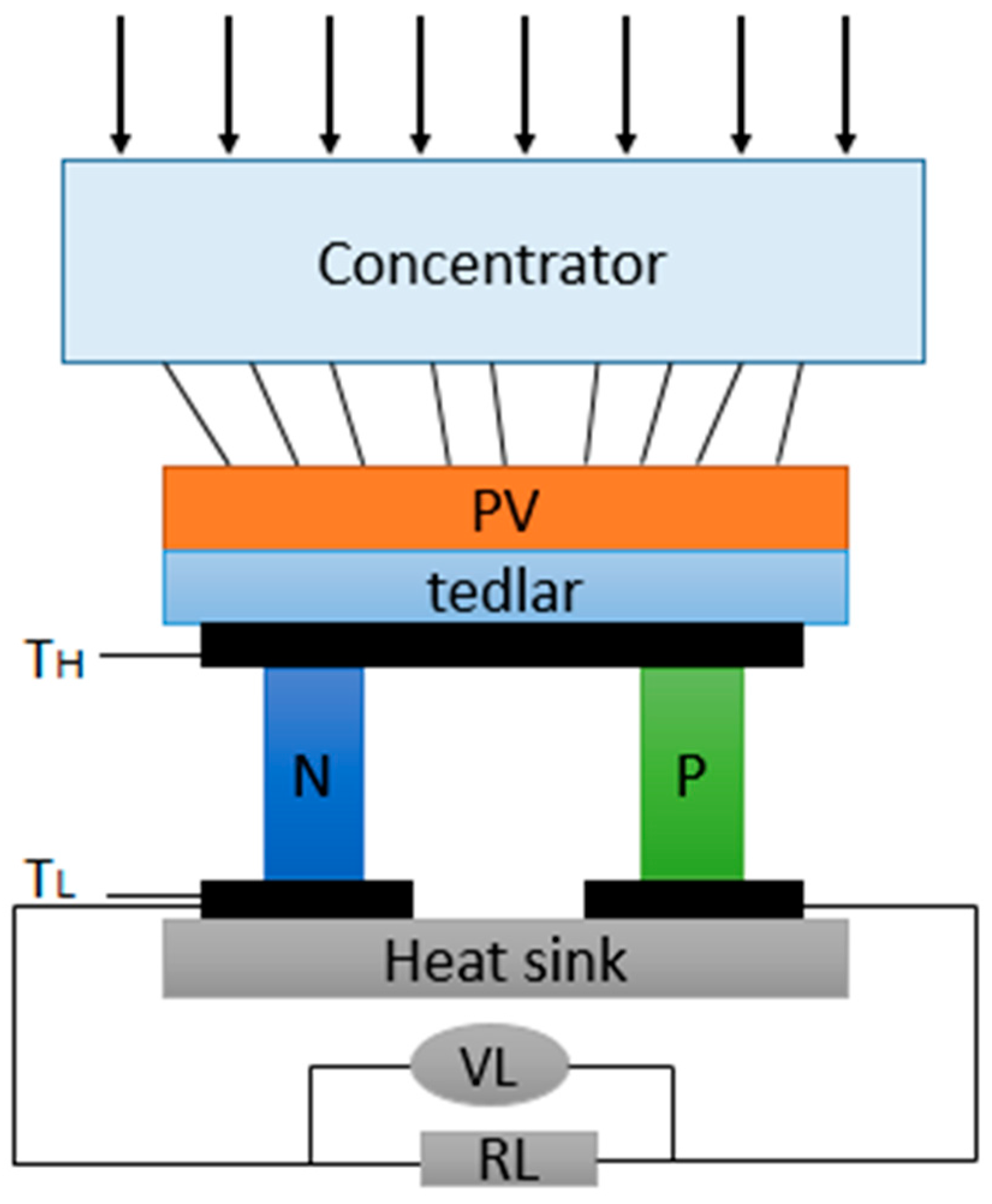
2. Model Description of a Hybrid PV-TE System
- The temperature of the PV module and heat sink module is uniform.
- Heat is transferred in only one dimension.
2.1. PV Module
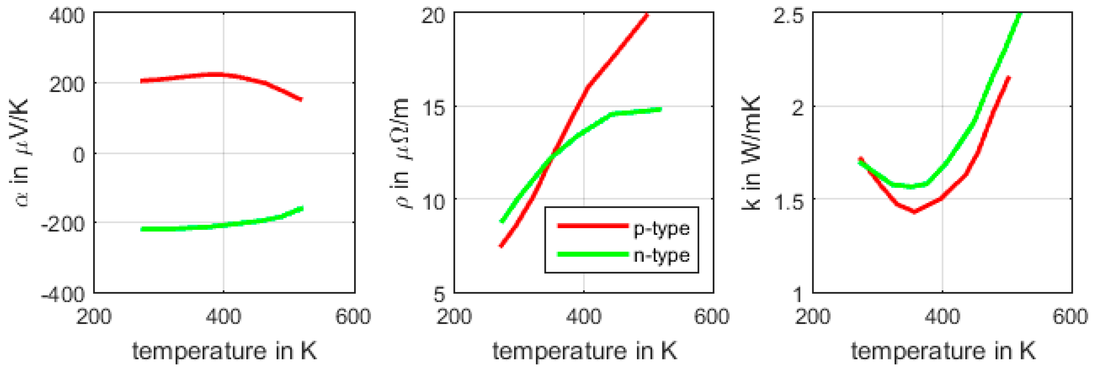
2.2. TEG Module
2.3. Overall Electrical Output and Efficiency of PV-TEG System
3. Analysis and Optimization of the Hybrid System’s Performance
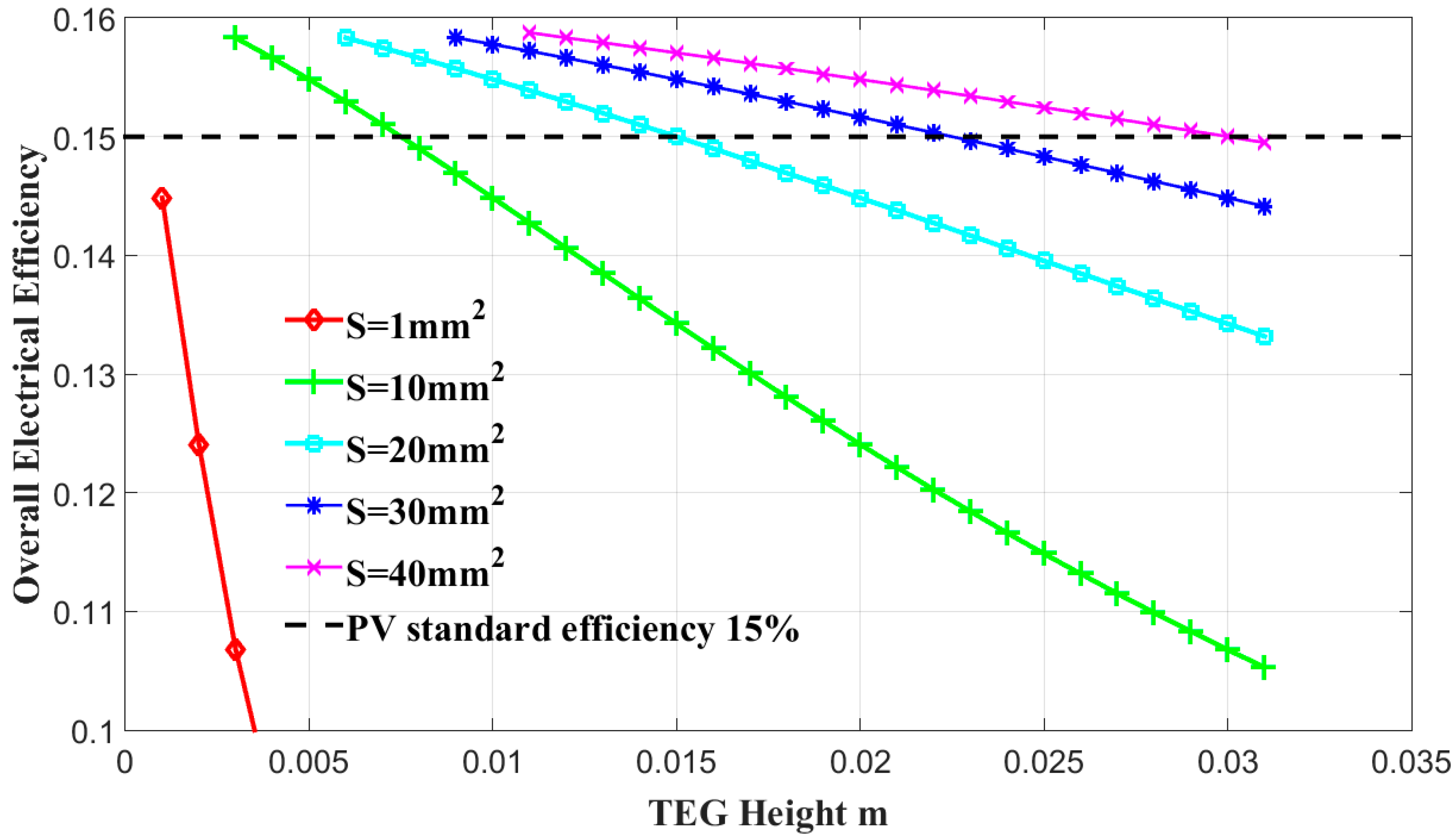
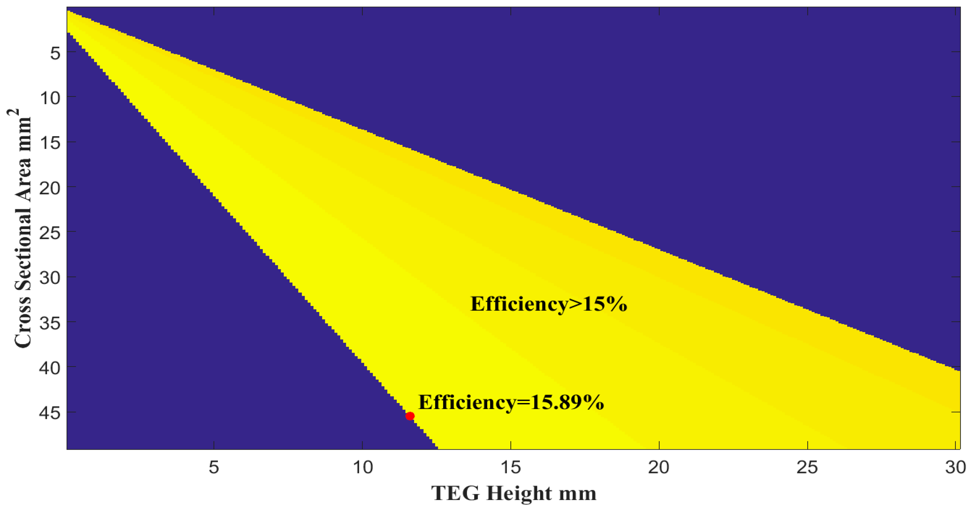
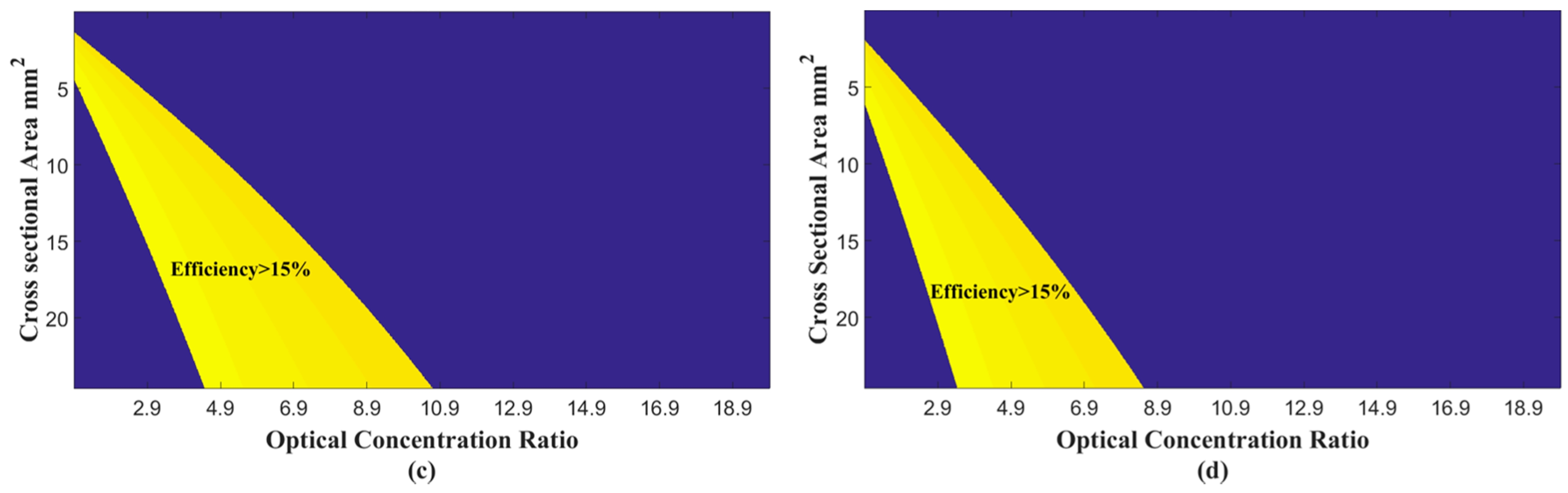
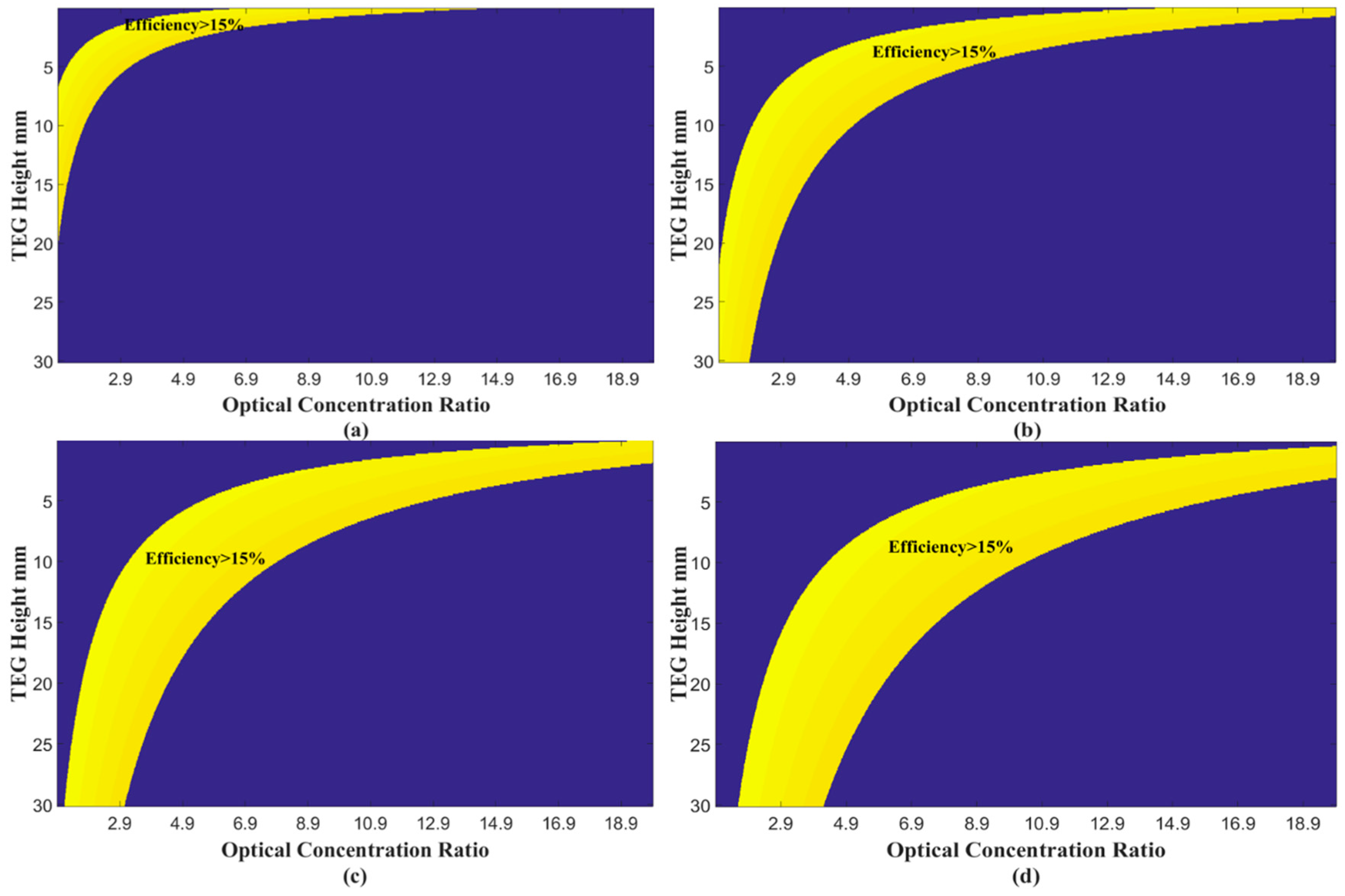
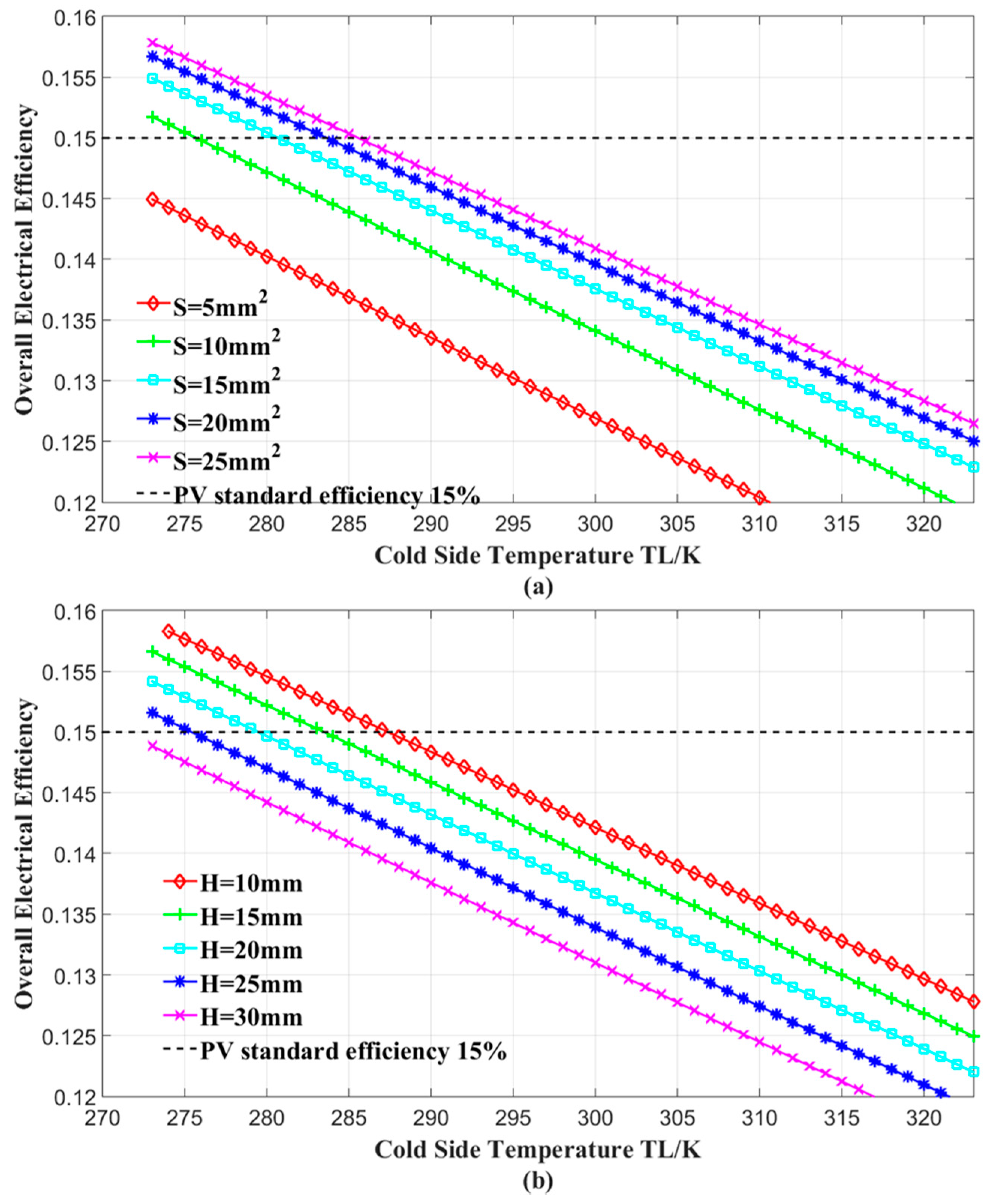
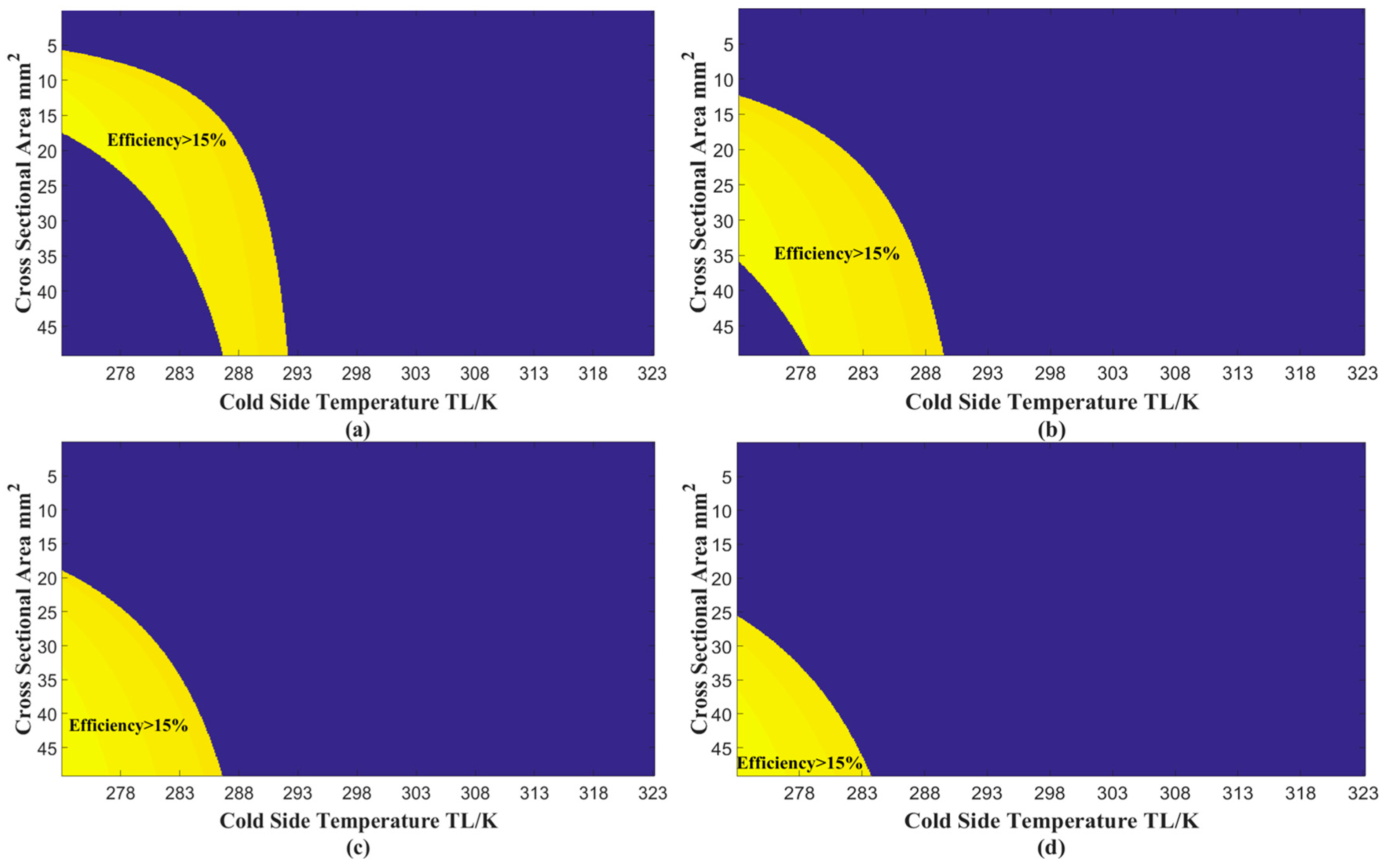
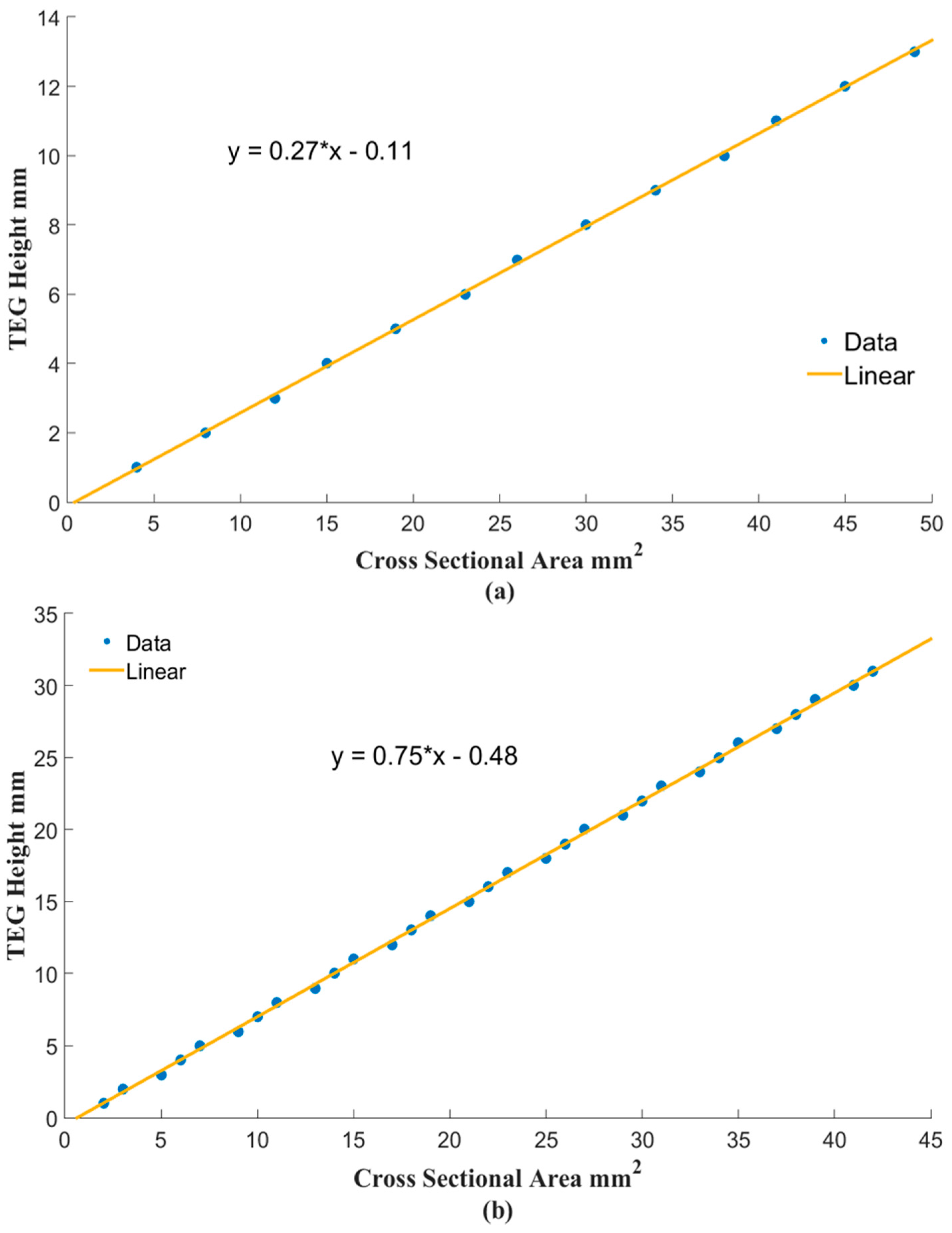
3.1. Geometric Parameters of TEG
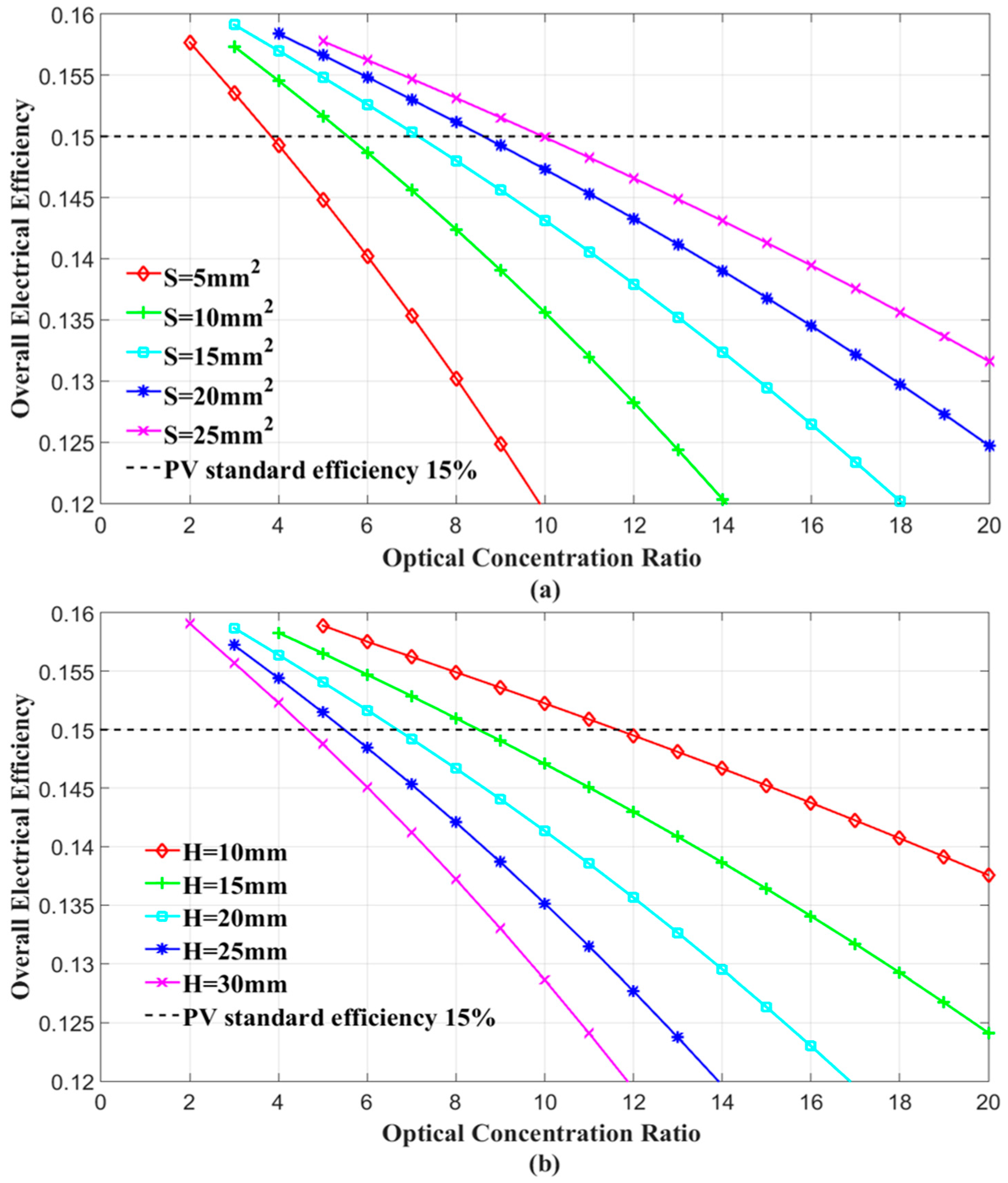
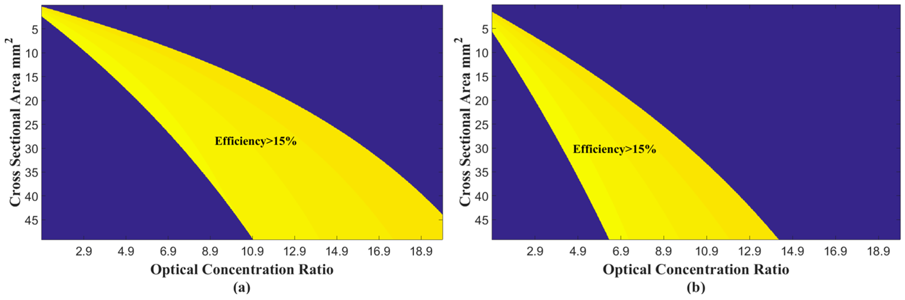
3.2. Solar Irradiation
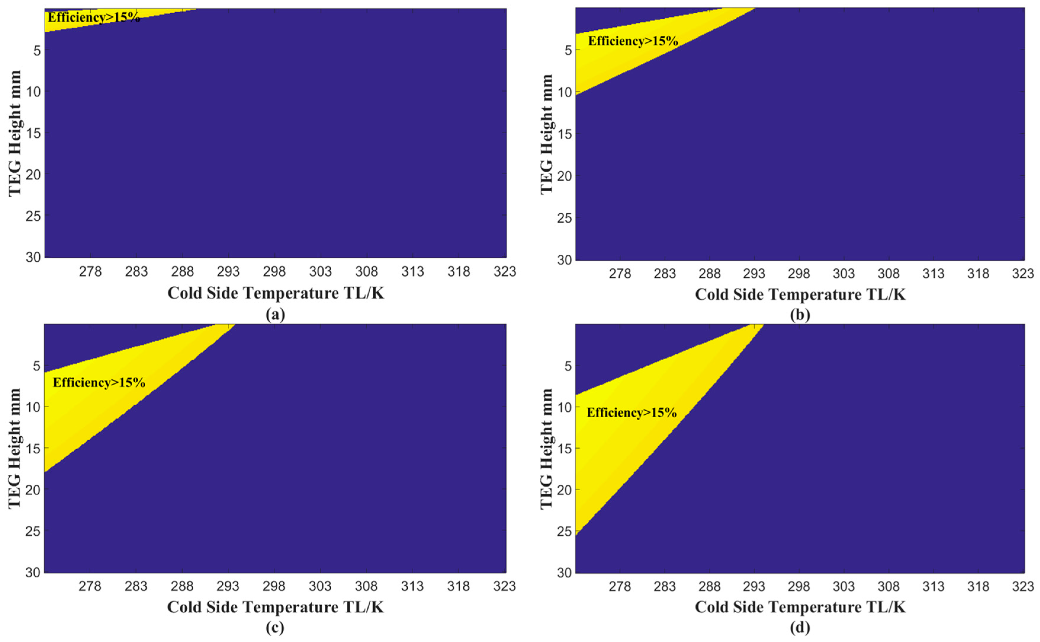
3.3. Cold Side Temperature
4. Conclusions
Acknowledgments
Author contributions
Conflicts of Interest
Nomenclature
| area, | PV temperature, | |||
| Concentration ratio | hot side temperature of TE, | |||
| electricity generation of PV module, | cold side temperature of TE, | |||
| solar radiation obtained by the solar concentrator | Greek Symbols | |||
| radiation heat transfer coefficient on outer surface, | absorptivity | |||
| convection heat transfer coefficient on outer surface, | packing factor | |||
| operating current, | solar cell temperature coefficient, | |||
| thermal conductivity, | efficiency | |||
| total thermal conductance of a TE module, | emissivity | |||
| thickness, | electric conductivity | |||
| electricity outputs, | Subscripts | |||
| heat conducted in thermoelectric modules, | air | |||
| total electrical resistance of a TE module, | n-type | |||
| load resistance, | p-type | |||
| wind velocity, | PV module | |||
| total Seebeck coefficient of a TE module, | the TEG module | |||
References
- Li, G.Q.; Ji, J.; Zhang, G.; He, W.; Chen, X.; Chen, H.B. Performance analysis on a novel micro-channel heat pipe evacuated tube solar collector-incorporated thermoelectric generation. Int. J. Energy Res. 2016, 40, 2117–2127. [Google Scholar] [CrossRef]
- Li, G.Q.; Zhang, G.; He, W.; Ji, J.; Lv, S.; Chen, X.; Chen, H.B. Performance analysis on a solar concentrating thermoelectric generator using the micro-channel heat pipe array. Energy Convers. Manag. 2016, 112, 191–198. [Google Scholar] [CrossRef]
- Van Sark, W. Feasibility of photovoltaic thermoelectric hybrid modules. Appl. Energy 2011, 88, 2785–2790. [Google Scholar] [CrossRef]
- Dallan, B.S.; Schumann, J.; Lesage, F.J. Performance evaluation of a photoelectric-thermoelectric cogeneration hybrid system. Sol. Energy 2015, 118, 276–285. [Google Scholar] [CrossRef]
- Wang, N.; Han, L.; He, H.; Park, N.-H.; Koumoto, K. A novel high-performance photovoltaic-thermoelectric hybrid device. Energy Environ. Sci. 2011, 4, 3676–3679. [Google Scholar] [CrossRef]
- Beeri, O.; Rotem, O.; Hazan, E.; Katz, E.A.; Braun, A.; Gelbstein, Y. Hybrid photovoltaic thermoelectric system for concentrated solar energy conversion: Experimental realization and modeling. J. Appl. Phys. 2015, 118. [Google Scholar] [CrossRef]
- Rezania, A.; Rosendahl, L.A. Feasibility and parametric evaluation of hybrid concentrated photovoltaic-thermoelectric system. Appl. Energy 2017, 187, 380–389. [Google Scholar] [CrossRef]
- Lamba, R.; Kaushik, S.C. Modeling and performance analysis of a concentrated photovoltaic-thermoelectric hybrid power generation system. Energy Convers. Manag. 2016, 115, 288–298. [Google Scholar] [CrossRef]
- Cui, T.F.; Xuan, Y.M.; Li, Q. Design of a novel concentrating photovoltaic-thermoelectric system incorporated with phase change materials. Energy Convers. Manag. 2016, 112, 49–60. [Google Scholar] [CrossRef]
- Liao, T.J.; Lin, B.H.; Yang, Z.M. Performance characteristics of a low concentrated photovoltaic-thermoelectric hybrid power generation device. Int. J. Therm. Sci. 2014, 77, 158–164. [Google Scholar] [CrossRef]
- Xu, Y.P.; Xuan, Y.M.; Yang, L.L. Full-spectrum photon management of solar cell structures for photovoltaic-thermoelectric hybrid systems. Energy Convers. Manag. 2015, 103, 533–541. [Google Scholar] [CrossRef]
- Su, S.H.; Liu, T.; Wang, Y.; Chen, X.H.; Wang, J.T.; Chen, J.C. Performance optimization analyses and parametric design criteria of a dye-sensitized solar cell thermoelectric hybrid device. Appl. Energy 2014, 120, 16–22. [Google Scholar] [CrossRef]
- Ju, X.; Wang, Z.F.; Flamant, G.; Li, P.; Zhao, W.Y. Numerical analysis and optimization of a spectrum splitting concentration photovoltaic-thermoelectric hybrid system. Sol. Energy 2012, 86, 1941–1954. [Google Scholar] [CrossRef]
- Wu, Y.-Y.; Wu, S.-Y.; Xiao, L. Performance analysis of photovoltaic-thermoelectric hybrid system with and without glass cover. Energy Convers. Manag. 2015, 93, 151–159. [Google Scholar] [CrossRef]
- Li, G.Q.; Zhao, X.D.; Ji, J. Conceptual development of a novel photovoltaic-thermoelectric system and preliminary economic analysis. Energy Convers. Manag. 2016, 126, 935–943. [Google Scholar] [CrossRef]
- Kossyvakis, D.N.; Voutsinas, G.D.; Hristoforou, E.V. Experimental analysis and performance evaluation of a tandem photovoltaic-thermoelectric hybrid system. Energy Convers. Manag. 2016, 117, 490–500. [Google Scholar] [CrossRef]
- Zhang, Y.T.; Xuan, Y.M. Biomimetic omnidirectional broadband structured surface for photon management in photovoltaic-thermoelectric hybrid systems. Sol. Energy Mater. Sol. Cells 2016, 144, 68–77. [Google Scholar] [CrossRef]
- Lin, J.; Liao, T.J.; Lin, B.H. Performance analysis and load matching of a photovoltaic-thermoelectric hybrid system. Energy Convers. Manag. 2015, 105, 891–899. [Google Scholar] [CrossRef]
- Park, K.-T.; Shin, S.-M.; Tazebay, A.S.; Um, H.-D.; Jung, J.-Y.; Jee, S.-W.; Oh, M.-W.; Park, S.-D.; Yoo, B.Y.; Yu, C.; et al. Lossless hybridization between photovoltaic and thermoelectric devices. Sci. Rep. 2013, 3. [Google Scholar] [CrossRef] [PubMed]
- Hashim, H.; Bomphrey, J.J.; Min, G. Model for geometry optimisation of thermoelectric devices in a hybrid PV/TE system. Renew. Energy 2016, 87, 458–463. [Google Scholar] [CrossRef]
- Jaworski, M.; Bednarczyk, M.; Czachor, M. Experimental investigation of thermoelectric generator (TEG) with PCM module. Appl. Therm. Eng. 2016, 96, 527–533. [Google Scholar] [CrossRef]
- Najafi, H.; Woodbury, K.A. Modeling and analysis of a combined photovoltaic-thermoelectric power generation system. J. Sol. Energy Eng. 2013, 135, 1–8. [Google Scholar] [CrossRef]
- Li, G.Q.; Pei, G.; Ji, J.; Su, Y.H. Outdoor overall performance of a novel air-gap-lens-walled compound parabolic concentrator (ALCPC) incorporated with photovoltaic/thermal system. Appl. Energy 2015, 144, 214–223. [Google Scholar] [CrossRef]
- Li, G.Q.; Pei, G.; Ji, J.; Yang, M.; Su, Y.H.; Xu, N. Numerical and experimental study on a PV/T system with static miniature solar concentrator. Sol. Energy 2015, 120, 565–574. [Google Scholar] [CrossRef]
- Watmuff, J.H.; Charters, W.W.S.; Proctor, D. Solar and wind induced external coefficients—Solar collectors. Complex 1977, 2, 56. [Google Scholar]
- Chow, T.T.; He, W.; Ji, J. Hybrid photovoltaic-thermosyphon water heating system for residential application. Sol. Energy 2006, 80, 298–306. [Google Scholar] [CrossRef]
- Ding, L.C.; Akbarzadeh, A.; Date, A. Performance and reliability of commercially available thermoelectric cells for power generation. Appl. Therm. Eng. 2016, 102, 548–556. [Google Scholar] [CrossRef]
- Gao, J.-L.; Du, Q.-G.; Zhang, X.-D.; Jiang, X.-Q. Thermal Stress Analysis and Structure Parameter Selection for a Bi2Te3-Based Thermoelectric Module. J. Electron. Mater. 2011, 40, 884–888. [Google Scholar] [CrossRef]


| Parameters | Symbol | Value | References |
|---|---|---|---|
| Ambient temperature | 298 K | [14] | |
| Solar irradiation | 1000 | - | |
| Absorptivity of PV module | 0.9 | [14] | |
| Thickness of PV | 0.0003 | [14] | |
| Thickness of tedlar | 0.000175 | [14] | |
| Conductivity of PV | 148 | [14] | |
| Conductivity of tedlar | 0.2 | [14] | |
| Emissivity of PV | 0.88 | [22] | |
| Temperature coefficient | 0.004 | [23,24] | |
| Area of PV | 0.0001 | - | |
| PV efficiency at standard condition | 0.15 | [24] |
© 2016 by the authors; licensee MDPI, Basel, Switzerland. This article is an open access article distributed under the terms and conditions of the Creative Commons Attribution (CC-BY) license (http://creativecommons.org/licenses/by/4.0/).
Share and Cite
Li, G.; Chen, X.; Jin, Y. Analysis of the Primary Constraint Conditions of an Efficient Photovoltaic-Thermoelectric Hybrid System. Energies 2017, 10, 20. https://doi.org/10.3390/en10010020
Li G, Chen X, Jin Y. Analysis of the Primary Constraint Conditions of an Efficient Photovoltaic-Thermoelectric Hybrid System. Energies. 2017; 10(1):20. https://doi.org/10.3390/en10010020
Chicago/Turabian StyleLi, Guiqiang, Xiao Chen, and Yi Jin. 2017. "Analysis of the Primary Constraint Conditions of an Efficient Photovoltaic-Thermoelectric Hybrid System" Energies 10, no. 1: 20. https://doi.org/10.3390/en10010020