
Analysis of Micronized Charcoal for Use in a Liquid Fuel Slurry


1
Department of Biosystems and Agricultural Engineering, Oklahoma State University, 111 Agricultural Hall, Stillwater, OK 74078, USA
2
Department of Biological and Agricultural Engineering, North Carolina State University, Campus Box 7625, Raleigh, NC 27695, USA
*
Author to whom correspondence should be addressed.
Energies 2017, 10(1), 25; https://doi.org/10.3390/en10010025
Submission received: 21 September 2016
/
Revised: 16 December 2016
/
Accepted: 19 December 2016
/
Published: 27 December 2016
(This article belongs to the Special Issue Biomass Chars: Elaboration, Characterization and Applications)
Abstract
:Yellow poplar (Liriodendron tulipifera) was chosen as the woody biomass for the production of charcoal for use in a liquid fuel slurry. Charcoal produced from this biomass resulted in a highly porous structure similar to the parent material. Micronized particles were produced from this charcoal using a multi-step milling process and verified using a scanning electron microscope and laser diffraction system. Charcoal particles greater than 50 µm exhibited long needle shapes much like the parent biomass while particles less than 50 µm were produced with aspect ratios closer to unity. Laser diffraction measurements indicated D10, D50, and D90 values of 4.446 µm, 15.83 µm, and 39.69 µm, respectively. Moisture content, ash content, absolute density, and energy content values were also measured for the charcoal particles produced. Calculated volumetric energy density values for the charcoal particles exceeded the No. 2 diesel fuel that would be displaced in a liquid fuel slurry.
1. Introduction
Rudolph Diesel claimed in his original German patent the capability to operate his engine design on a variety of liquid, gaseous, and solid fuels [1]. Diesel conducted several experiments using dry coal dust as a solid fuel to support these claims [2]. Researchers further explored the use of solid fuels, primarily coal dust, throughout the early 20th century as an alternative to liquid fuels of the time [3]. German researchers were particularly interested in coal dust operating diesel engines as an alternative during the Second World War fuel shortages [2]. In the United States during the 1960s, researchers focused on carburation and injection issues plaguing the usage of coal dust as a safe and reliable fuel for diesel engines [4]. Many of these issues were resolved by using water as a carrier for the coal dust instead of air. The US Department of Energy funded several research grants aimed at developing usable coal-water slurries for diesel engines tied mainly to locomotives [5]. The culmination of this research suggested that the optimum slurry composition (mass basis) was 48% percent coal particles with an average size of 3 µm, 2% additives, and the balance water with less than one percent ash [5]. Using larger coal particles decreased time to sedimentation and required agitation before use [6]. Coal-water slurries required engine designs to achieve in-cylinder gas temperatures above 890 K for proper ignition and combustion [7]. Although coal-water slurries were successfully used as a fuel, the material properties of the coal particles created major wear issues. Engines running coal-water slurries exhibited component wear that was 2 to 20 times faster than identical engines running on No. 2 diesel fuel [5]. More recent studies have continued this research using other solid carbon sources such as carbon black from automotive tire waste and other petroleum based wastes [8,9,10,11,12].
Studies on alternative fuel sources have placed focus on renewable and bio-based fuel sources in recent years. Biomass derived charcoal or biochar is one renewable solid fuel that is similar to coal [13]. Some charcoal slurry properties have been investigated for use in diesel engines. Efforts to incorporate dry biomass and biochar dust have been attempted in recent years, but most of the work focused on incorporating these solid particles into a liquid [14]. N’kpomin et al. [15] evaluated ternary mixtures of charcoal, oil, and water through viscosity measurements. For a particular mass percent of charcoal, particle sizes below 4 µm significantly increased viscosity due to the increased effect of surface forces. Recent studies examined ternary mixtures of biochar-glycerol-water and determined that the slurry was most stable when the liquid phase of the slurry consisted of 90% by mass glycerol with the remainder as water [16]. Biochar sedimentation was much lower for slurries with less water in the liquid phase.
Biomass derived charcoal ash studied by Ellem and Mulligan [17] were found to contain mostly silicon (SiO2), aluminum (Al2O3), iron (Fe2O3), calcium (CaO), magnesium (MgO), sodium (NaO2), potassium (K2O), and phosphorus (P2O5). It was noted that mechanical separation and leaching would be effective in removing the majority of ashes within biomass charcoals. Compared to coal, ash contained within biomass derived charcoal slurries produced much lower levels of abrasive wear in many studies [18]. The easy removal of ash and lower abrasive wear of charcoal slurries open the possibility of producing an energy-dense, low-ash fuel slurry that could be used in multiple applications. Reciprocating piston diesel engines such as medium and low speed diesels used for locomotion would be a likely candidate that would benefit from such a fuel, but even gas turbines could operate on a biomass derived charcoal slurry if ash removal could achieve acceptable levels to minimize slagging and other related issues [19].
The goal of this research was to develop and analyze charcoal particles that could be used to displace current medium speed diesel engine liquid fuels, such as No. 2 diesel fuel, as part of a liquid fuel slurry. Experiments were conducted to answer the following questions:
- Can charcoal be effectively milled to produce micronized particles (<1 mm diameter)?
- How does the size of the charcoal particle affect the shape and structure?
- What are typical values for the physical and chemical properties of biomass derived charcoal particles?
- How does the displacement of liquid fuel with charcoal particles affect the liquid fuel’s energy density?
2. Materials and Methods
Woody biomass was chosen as the feedstock for the charcoal produced during this research. Yellow poplar (Liriodendron tulipifera) was chosen as the species for carbonization. The yellow poplar tree has a characteristically long limbless trunk that has the potential to produce a much greater volume of dry wood than other denser species such as oak [20]. Three logs were cut from Fishel Family Farms (Clemmons, NC, USA) and were allowed to lay in direct sunlight outdoors for three hours with an average ambient temperature of 32 °C. This short warming period heated the sap and tissue in the cambium layer of the wood which aided in the removal of the bark from the wood. Bark separation is a mechanical process used to remove any windblown silicates and other ashes present in the bark from the material used for charcoal. A 3 cm wide strip of bark was removed along the length of each log using a drawknife. A small flat edge such as a putty knife was then inserted along the cambium later between the inner wood and the bark. The bark was then peeled from the log by hand in one solid sheet as shown in Figure 1 and discarded.
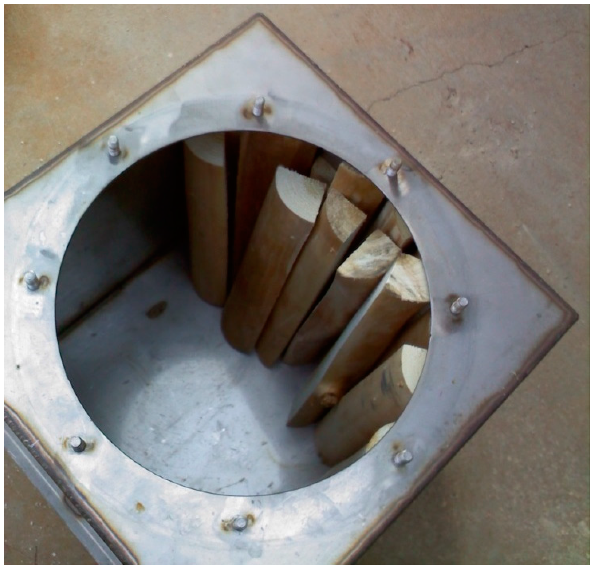
After bark separation, the logs were cut to lengths of roughly 430 mm and were either halved or quartered depending on initial diameter to produce pieces that were similar in overall volume. These pieces were then placed in a forced-air dryer at 108 °C for 16 h. The pieces were then allowed to equilibrate to room temperature before handling and recording their mass. The cut and dried wood pieces were then placed in a custom stainless steel chamber designed for lab-scale charcoal production (Figure 2).
The chamber measured 407 mm × 407 mm × 458 mm (W × D × H) and contained a 330 mm diameter round opening on the top. Two 3.175 mm nominal National Pipe Taper (0.125-27 NPT) couplers were welded into one side of the chamber to allow for insertion of pipe nipples for exhausting combustible gases during carbonization. The chamber was sealed and placed into a high temperature furnace (Iguana, Paragon Industries, L.P., Mesquite, TX, USA). The heating schedule programmed into the furnace controller consisted of a full rate heating until a temperature of 250 °C was achieved and then a rate of 100 °C per hour until 700 °C was reached. The furnace was then programmed to turn off at 700 °C. The furnace doors were then opened and the chamber was allowed to cool overnight. Since pyrolysis of the parent biomass should near completion at 700 °C, this high temperature process was selected to produce an energy dense, low-oxygen charcoal product [21]. A higher temperature would favor carbon reduction reactions that decrease charcoal yield with little gain in charcoal energy density, and a lower temperature would not allow complete pyrolysis and would produce a higher charcoal yield at the cost of charcoal energy density [22].
The charcoal was then processed using a multi-step milling process (Figure 3).
The process began with whole charcoal as produced by the furnace. The whole charcoal was fed into a Wiley mill (Model 4, Thomas Scientific, Sweedsboro, NJ, USA) that used a 1 mm screen. Charcoal that exited the Wiley mill was placed into a No. 100 (149 µm) sieve. Charcoal particles that could not pass through the sieve were processed further through a burr mill until the particles were able to pass through the No. 100 sieve. Charcoal particles that passed through the No. 100 sieve were loaded into a custom lab-scale ball mill. The lab-scale ball mill consisted of a three-liter polypropylene bottle as the tumbling cylinder placed between two electric conveyor rollers mounted to a frame. The three-liter bottle was loaded with twelve 12.7 mm steel spheres and filled to half capacity with ground charcoal. The three-liter bottle was rotated at a constant speed of 1 Hz. After a minimum residence time of 24 h, the charcoal particles were removed and placed into a No. 325 (44 µm) sieve. Charcoal particles that passed through the No. 325 sieve were placed into storage for further analysis and the remainder was placed back into the ball mill.
Initial evaluation of the milling process was conducted by hand sieving a random sample of the material leaving the first process (Wiley mill). Since the Wiley mill incorporated a 1000 µm screen, a No. 35 (500 µm) and No. 100 sieve were chosen for quick evaluation of the sample. The No. 35 sieve was placed upon the No. 100 sieve and installed over a receiver pan. A sample was placed into the No. 35 sieve and agitated by hand for 60 s. The mass of the material remaining on each sieve and within the receiver was recorded.
2.1. Particle Analysis
Samples were randomly selected from the charcoal particles produced by the multi-step milling process. Initial particle analysis involved sending samples to be analyzed by a scanning electron microscope (SEM) with an incorporated energy-dispersive X-ray detector. The high resolution images produced by the SEM were used to describe the relative shape and size of the particles produced by the multi-step milling process. The dispersive X-ray detector allowed for elemental analysis of portions of the viewable image. Areas of the sample containing ash were selected for this elemental analysis.
Particle size and distribution were also quantified using a laser diffraction system (Spraytec, Malvern Instruments Ltd., Worcestershire, UK). The system was calibrated to measure particle sizes from 0.1 µm to 1000 µm. Sample charcoal particles were entrained in an air stream that dispersed the particles as they passed between the laser emitter and receiver. Five test replications were performed.
2.2. Physical and Chemical Property Analysis
One of the goals of this research was to quantify a few of the physical and chemical properties of biomass derived charcoal particles. Moisture content, ash content, absolute density, and energy content were the four properties quantified. Moisture and ash content were selected to quantify the amount of ash and water that the charcoal would contribute to a fuel slurry. Absolute density was measured to determine the volume displaced by the charcoal particles when added to a liquid fuel slurry.
The moisture content of the charcoal particles was measured using an analytical balance and muffle furnace (Isotemp Muffle Furnace 10-550-126, Thermo Fisher Scientific, Waltham, MA, USA). Empty crucibles were placed in the muffle furnace for one hour at 750 °C to remove any residual surface deposits. After cooling in a desiccator for an hour, the crucible mass was recorded to the nearest 0.0001 g. Each crucible was filled with a one-gram sample of charcoal particles and a new crucible mass was recorded. The crucibles were placed in the muffle furnace at 105 °C for 24 h. The crucibles were then removed and placed in the desiccator for one hour to cool. A new oven-dry mass was then recorded for each crucible. The wet-basis (w.b.) moisture content was calculated using the standard method [23]. The moisture content analysis was replicated four times for each charcoal particle sample.
The ash content of the charcoal particles was measured using the analytical balance and muffle furnace as a continuation of the moisture content analysis procedure. The oven-dry charcoal particles were removed from the desiccator and placed in the muffle furnace at 750 °C for 20 h. The crucibles were then removed and placed in a desiccator to cool for one hour. A new mass value was recorded for the cooled crucible and remaining ash. The ash content was calculated as a percentage of the oven-dry charcoal particle sample mass. Used crucibles were wiped clean and placed in the muffle furnace at 750 °C for one hour and then allowed to cool in a desiccator for reuse. The ash content analysis was replicated four times for each charcoal particle sample.
Absolute density of the charcoal particles was measured using a helium pycnometer (Accupyc 1330, Micrometrics, Norcross, GA, USA). The pycnometer was set to purge the sample and reference chambers before each volumetric measurement. The sample chamber insert was filled with charcoal particles and the mass of the sample was recorded to the nearest 0.0001 g. For each sample run, the pycnometer was set to perform 10 volumetric measurements and record the average. Absolute density was calculated by the pycnometer using the measured mass and absolute volume for each sample run. All seals and surfaces were wiped clean and were properly greased between each sample run. The absolute density analysis was replicated three times for each charcoal particle sample selected.
Energy content or higher heating value (HHV) of the charcoal particles was measured using a bomb calorimeter (CAL-2KECO, Digital Data Systems Pty. Ltd., Johannesburg, South Africa). A new steel crucible was fired in the muffle furnace at 800 °C for 10 min to remove any residual oils or other surface deposits. After cooling, the crucible mass was recorded to the nearest 0.0001 g. A 0.5 g sample of charcoal particles was selected for each run and placed into the crucible. A new mass was recorded and the actual sample mass was calculated. Firing wires and seals in the bomb calorimeter vessel were examined before each run and replaced if necessary. A cotton string was tied to the firing wire and placed against the charcoal particles in the crucible to act as an ignition source. The completed crucible assembly was placed into the bomb calorimeter vessel and charged with pure oxygen to a pressure of 2068 kPa. The HHV was measured by the bomb calorimeter for each sample in units of “BTU/pound”. SI units were calculated using ASAE Standard EP285.7 [24]. The energy content analysis was replicated three times for each charcoal particle sample.
3. Results and Discussions
Yellow poplar biomass was successfully prepared for carbonization and 14.8 kg was loaded into the furnace chamber. The carbonization process yielded 3.5 kg of yellow poplar charcoal or 24% of the weight of the parent biomass. This type of yield is consistent with low-oxygen biochars where overall yield is sacrificed to increase the energy density of the char.
The charcoal produced retained much of the original structure of the biomass as shown in Figure 4.
The lower mass value of the charcoal combined with little visual reduction in overall volume, suggested a low bulk density material. The low bulk density was due to the increase in the size of internal void spaces within the charcoal structure. This reduced the thickness of the structural walls resulting in a very porous structure requiring lower shearing forces than the parent biomass.
A multi-step milling process was developed to generate micronized charcoal. Initial evaluation of the milling process was conducted to determine the effectiveness of the initial step (Wiley mill) using a simple hand sieving method. A sample was collected after processing the charcoal through the Wiley mill. The recorded mass values for this process are presented in Table 1.
Almost the entire charcoal particle sample was able to pass through a sieve that is half the size of the screen within the mill and almost 80% of the charcoal particles passed through a No. 100 screen. Although this data was measured from a single sample selected from the charcoal exiting the first milling step, the analysis suggests that the charcoal material produced required less milling effort than similar materials, such as coal found in the literature.
3.1. Particle Analysis
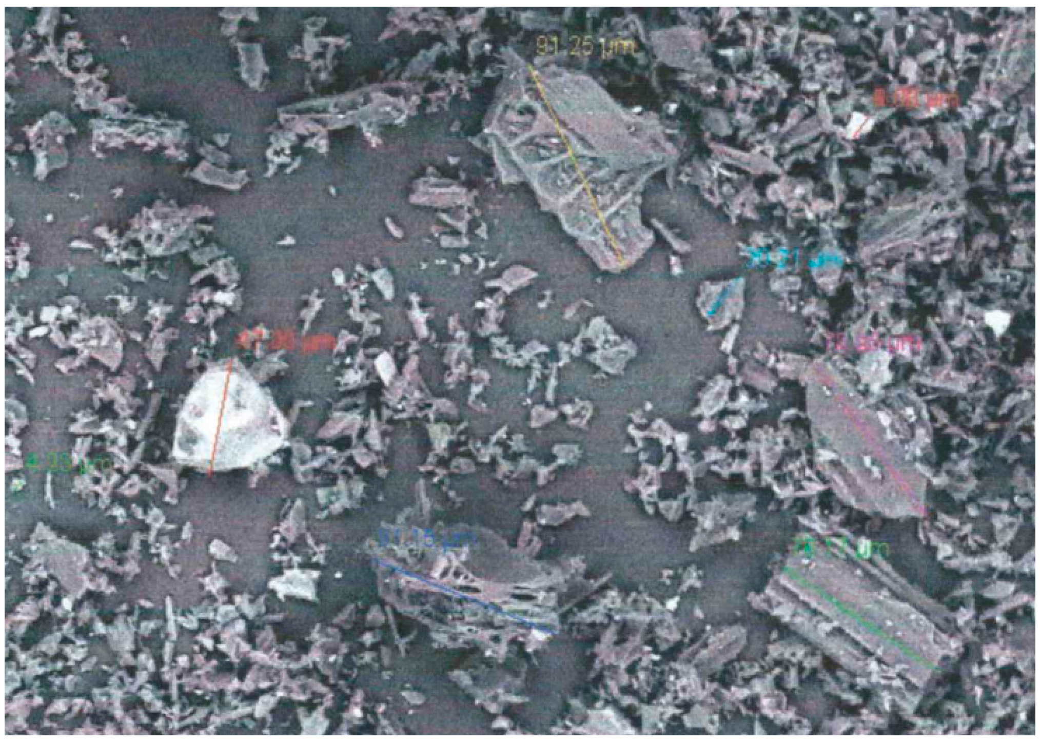
Initial sizing of the charcoal particles was obtained using images produced by a SEM. Figure 5 shows one of the images produced by the SEM using a magnification power of 400×.
Many of the ash particles contrast the charcoal particles in this image with a lighter color. The largest dimension of the particles was measured within the image as a qualitative measure of particle size. The four largest charcoal particles pictured in Figure 5 each measured approximately 90 µm while the largest ash particle measured approximately 50 µm. The smaller charcoal particles averaged 5 µm and the smaller ash particles averaged 7 µm. The larger charcoal particles tended to retain the cylindrical and porous structural arrangement of the biomass feedstock. Aspect ratios of these particles were much smaller, with needle-like shapes at the smallest values. The smaller particles (<50 µm) tended to be described as irregularly shaped with aspect ratios near unity. Similar observations have been made concerning aspect ratio measurements for ground wood particles [25] and biochar [26].
A portion of the SEM imagery was selected that contained several identifiable ash particles as a means to identify the elemental composition of the ash present in the sample. An energy-dispersive X-ray spectrometer attached to the SEM was used to analyze a selected portion of the sample for elemental composition. A sample area was selected that contained a large number of visible ash particles. The mass fractions determined by this analysis were highly dependent on the selected sample area and was not representative of the actual elemental mass fraction composition in the overall charcoal sample. This analysis did however identify that the ash present involved molecules containing calcium, potassium, and silicon, with some type of oxide being the most probable form. These are all common types of elemental ash found in biomass [17].
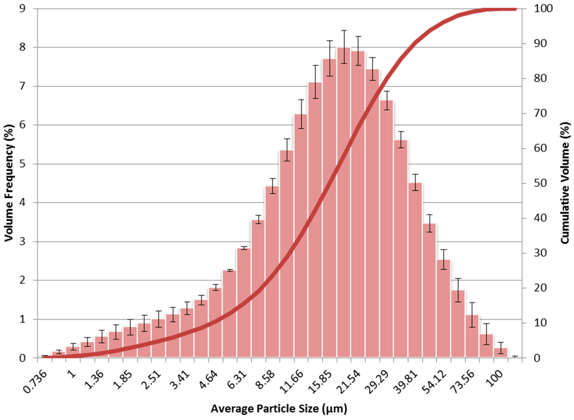
The size of the charcoal particles was quantified using the laser diffraction system. The system analyzed the particles measuring the volume frequency of particles falling within discrete size steps up to 1000 µm. The percentage of the overall sample volume occupied by particles within a particular size step was recorded for each sample run. The average percentage value and standard error for each size step were calculated for all of the sample runs. A histogram of this data is shown in Figure 6.
Measured sample particle sizes ranged from 0.736 µm to 116.59 µm with a median value or D50 of 15.83 µm. Two different types of mean diameters were calculated for the data. The Sauter mean diameter (D[3,2]) was measured as 9.166 µm and represents the mean particle size when taking into account the surface area of the particles. The De Brouckere mean diameter (D[4,3]) was measured as 19.59 µm and represents the mean particle size when taking into account the volume of the particles. The De Brouckere mean diameter is the more conservative mean value since it is very sensitive to the presence of larger particles in the sample. Since this research is concerned with the displacement of liquid fuel, the De Brouckere mean diameter was the one chosen to represent the mean particle size for the sample. The D10 and D90 values were determined as 4.446 µm and 39.69 µm, respectively. These values represent the points at which 10% and 90% of sample volume consists of particles that are of that particular size and smaller. 0% of the sample volume can be described as a particle sized within the range of these two values.
3.2. Physical and Chemical Property Analysis
Charcoal particle samples were randomly selected from the charcoal produced for this research after completing the multi-step milling process. Moisture content, ash content, absolute density, and energy content were measured for each of the samples. Moisture content was measured using a dry-basis (d.b.) calculation, but is presented as a w.b. value (Figure 7a).
The w.b. moisture content ranged from 4.55% to 6.16% with a median value of 5.06%. The overall distribution was skewed towards the lower values. Ash content (Figure 7b) held a much tighter distribution of measured values. The d.b. ash content ranged from 1.02% to 1.46% with a median value of 1.34%. Beyond a few low ash samples, the majority of the measured values were towards the higher end of the data range. These values agreed with the values found in the literature [27].
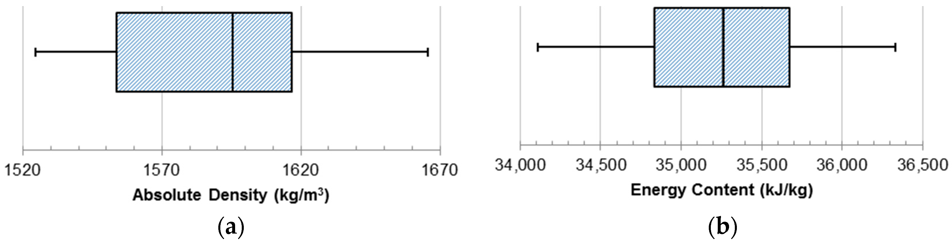
Absolute density was measured to describe the density of the individual charcoal particles. When added to a liquid fuel slurry, the volume of the particles would displace an equal volume of the liquid fuel. The absolute density was calculated through the measurement of the volume of the particles in a sample and the measured mass of the sample. The calculated absolute density for the charcoal samples is presented in Figure 8a. The absolute density ranged from 1525 kg/m3 to 1667 kg/m3 with a median value of 1596 kg/m3.
The energy content of the charcoal particles was measured with the bomb calorimeter to determine the energy that would evolve within an engine combustion chamber (Figure 8b). The energy content ranged from 34,107.8 kJ/kg to 36,329.6 kJ/kg with a median value of 35,261.3 kJ/kg. The energy density measurement data were symmetrically distributed about the median value. This energy content was determined as a mass basis but can be converted to a volumetric basis using the measured density of the charcoal particle. Energy per unit volume is much more descriptive of the energy density of a liquid fuel. Taking into consideration the full range of values for the absolute density, the volumetric energy content for charcoal was determined to be within the range of 52,014.4 MJ/m3 to 60,560.4 MJ/m3 for the measured samples. Considering that No. 2 diesel fuel has an average density of 851 kg/m3 and a HHV of 38,362.5 MJ/m3 on a volumetric basis, the charcoal was found to have a much higher volumetric energy density [28].
This higher energy density is a direct result of the high carbon charcoal produced through the high temperature carbonization process. According to the literature, the energy density (HHV) of the parent yellow poplar biomass is 18.12 MJ/kg [29]. Using the lower range of the measured energy density (HHV) for the yellow poplar charcoal particles and the process yield, only 45% of the energy contained in the parent biomass remains in the charcoal product. A lower temperature carbonization process would yield more charcoal material with a higher overall amount of energy from the parent biomass, but the energy density of the material would be much lower. For high energy density charcoal production to be a viable option, the parent biomass energy fraction contained in the syngas and pyrolysis oil must have value in the production process or as a product elsewhere.
4. Conclusions
Biomass derived charcoal was produced, milled, and analyzed for its potential as a micronized particle to be used in a liquid fuel slurry. Particle shape and size was determined using both qualitative and quantitative methods. Conclusions resulting from this study were:
- A multi-step milling process was developed that successfully produced micronized particles with 90% of the sample volume consisting of particles smaller than 50 µm. Charcoal particles less than 1000 µm could be effectively generated in a single milling step, but charcoal particles less than 50 µm required further processing steps.
- Particles produced that were greater than 50 µm exhibited longer needle shapes with high aspect ratios when viewed at high magnification levels. Particles smaller than 50 µm exhibited aspect ratios that were much closer to unity. Since liquid fuels form spherical droplets with aspect ratios close to unity, a successful milling process should produce charcoal particle with sizes less than 50 µm.
- Physical and chemical property analyses of the charcoal particles determined that the charcoal particle density was much higher than No. 2 diesel fuel. This increase in energy density is achieved through a high-temperature, lower-yielding carbonization process. Therefore, displacing a liquid fuel with a charcoal particle would increase the theoretical volumetric energy density of the fuel mixture. The resulting slurry would be appropriate for use in medium speed and low speed diesel engines whenever volumetric energy density is desirable. Further processing would be required to produce a very low-ash, volumetrically energy dense slurry capable of meeting the necessary requirements for gas turbine systems.
Acknowledgments
This material was based upon work made possible through support by the North Carolina Agricultural Foundation, Inc. and Carolina Greenhouses, Inc.
Author Contributions
John M. Long and Michael D. Boyette conceived and designed the experiments; John M. Long performed the experiments and analyzed the data; Michael D. Boyette contributed reagents/materials/analysis tools; John M. Long and Michael D. Boyette wrote the paper.
Conflicts of Interest
The authors declare no conflict of interest. The founding sponsors had no role in the design of the study; in the collection, analyses, or interpretation of data; in the writing of the manuscript, and in the decision to publish the results.
References
- Diesel, R. Arbeitsverfahren und Ausführungsart für Verbrennungskraftmaschinen. DE67207A, 28 February 1982. (In German)[Google Scholar]
- Soehngen, E. Development of Coal-Burning Diesel Engines in Germany; National Technical Information Service: Alexandria, VA, USA, 1976. [Google Scholar]
- McMillian, M.; Webb, H. Coal-fueled diesels: Systems development. J. Eng. Gas Turbines Power 1989, 111, 485–490. [Google Scholar] [CrossRef]
- Ryan, T. Coal-fueled diesel development: A technical review. J. Eng. Gas Turbines Power 1994, 116, 740–748. [Google Scholar] [CrossRef]
- Caton, J.A.; Hsu, B.D. General electric coal-fueled diesel engine program (1982–1993): A technical review. J. Eng. Gas Turbines Power 1994, 116, 749–757. [Google Scholar] [CrossRef]
- Chen, X.; Zhao, L.; Zhang, X.; Qian, C. An investigation on characteristics of coal–water slurry prepared from the solid residue of plasma pyrolysis of coal. Energy Convers. Manag. 2012, 62, 70–75. [Google Scholar] [CrossRef]
- Hsu, B.; Flynn, P.L. Preliminary study of using coal-water slurry fuel in GE-7FDL medium speed diesel engine. In Proceedings of the 18th International Congress on Combustion Engines, Tianjin, China, 5–8 June 1989.
- Wamankar, A.K.; Murugan, S. Experimental investigation of carbon black–water–diesel emulsion in a stationary DI diesel engine. Fuel Process. Technol. 2014, 125, 258–266. [Google Scholar] [CrossRef]
- Wamankar, A.K.; Murugan, S. Combustion, performance and emission of a diesel engine fuelled with diesel doped with carbon black. Energy 2015, 86, 467–475. [Google Scholar] [CrossRef]
- Wamankar, A.K.; Murugan, S. Combustion, performance and emission characteristics of a diesel engine with internal jet piston using carbon black-water-diesel emulsion. Energy 2015, 91, 1030–1037. [Google Scholar] [CrossRef]
- Wamankar, A.K.; Satapathy, A.K.; Murugan, S. Experimental investigation of the effect of compression ratio, injection timing & pressure in a DI (direct injection) diesel engine running on carbon black-water-diesel emulsion. Energy 2015, 93, 511–520. [Google Scholar]
- Molino, A.; Erto, A.; Di Natale, F.; Donatelli, A.; Iovane, P.; Musmarra, D. Gasification of granulated scrap tires for the production of syngas and a low-cost adsorbent for Cd(II) removal from wastewaters. Ind. Eng. Chem. Res. 2013, 52, 12154–12160. [Google Scholar] [CrossRef]
- Liu, Z.; Quek, A.; Hoekman, S.K.; Balasubramanian, R. Production of solid biochar fuel from waste biomass by hydrothermal carbonization. Fuel 2013, 103, 943–949. [Google Scholar] [CrossRef]
- Piriou, B.; Vaitilingom, G.; Veyssière, B.; Cuq, B.; Rouau, X. Potential direct use of solid biomass in internal combustion engines. Prog. Energy Combust. Sci. 2013, 39, 169–188. [Google Scholar] [CrossRef]
- N’kpomin, A.; Boni, A.; Antonini, G.; François, O. The deashed charcoal-oil-water mixture: A liquid fuel for biomass energetical valorization. Chem. Eng. J. Biochem. Eng. J. 1995, 60, 49–54. [Google Scholar] [CrossRef]
- Liu, P.; Zhu, M.; Zhang, Z.; Leong, Y.K.; Zhang, Y.; Zhang, D. An experimental study of rheological properties and stability characteristics of biochar-glycerol-water slurry fuels. Fuel Process. Technol. 2016, 153, 37–42. [Google Scholar] [CrossRef]
- Ellem, G.K.; Mulligan, C.J. Biomass char as a fuel for internal combustion engines. Asia-Pac. J. Chem. Eng. 2012, 7, 769–776. [Google Scholar] [CrossRef]
- Wamankar, A.K.; Murugan, S. Review on production, characterisation and utilisation of solid fuels in diesel engines. Renew. Sustain. Energy Rev. 2015, 51, 249–262. [Google Scholar] [CrossRef]
- Mehr-Homji, C.; Zachary, J.; Bromley, A. Gas turbine fuels-system design, combustion and operability. In Proceedings of the 39th Turbomachinery Symposium, Houston, TX, USA, 4–7 October 2010; pp. 4–7.
- Beck, D.E. Liriodendron tulipifera L. In Silvics of North America: 2. Hardwoods; Forest Service: Washington, DC, USA, 1990; pp. 406–416. [Google Scholar]
- Chen, T.; Wu, J.; Zhang, Z.; Zhu, M.; Sun, L.; Wu, J.; Zhang, D. Key thermal events during pyrolysis and CO2-gasification of selected combustible solid wastes in a thermogravimetric analyser. Fuel 2014, 137, 77–84. [Google Scholar] [CrossRef]
- Molino, A.; Chianese, S.; Musmarra, D. Biomass gasification technology: The state of the art overview. J. Energy Chem. 2016, 25, 10–25. [Google Scholar] [CrossRef]
- Wilhelm, L.R.; Suter, D.A.; Brusewitz, G.H. Drying and Dehydration. In Food & Process Engineering Technology; American Society of Agricultural Engineers: St. Joseph, MI, USA, 2004. [Google Scholar]
- American Society of Agricultural and Biological Engineers (ASABE). ASAE EP285.8 Use of SI (Metric) Units; American Society of Agricultural and Biological Engineers (ASABE): St. Joseph, MI, USA, 2014. [Google Scholar]
- Tannous, K.; Lam, P.; Sokhansanj, S.; Grace, J. Physical properties for flow characterization of ground biomass from Douglas Fir Wood. Part. Sci. Technol. 2013, 31, 291–300. [Google Scholar] [CrossRef]
- Shivaram, P.; Leong, Y.; Yang, H.; Zhang, D. Flow and yield stress behaviour of ultrafine Mallee biochar slurry fuels: The effect of particle size distribution and additives. Fuel 2013, 104, 326–332. [Google Scholar] [CrossRef]
- Molino, A.; Nanna, F.; Villone, A. Characterization of biomasses in the southern Italy regions for their use in thermal processes. Appl. Energy 2014, 131, 180–188. [Google Scholar] [CrossRef]
- Tyson, K.S.; McCormick, R. Biodiesel Handling and Use Guide; National Renewable Energy Laboratory (NREL): Golden, CO, USA, 2006. [Google Scholar]
- Na, B.; Ahn, B.; Lee, J. Changes in chemical and physical properties of yellow poplar (Liriodendron tulipifera) during torrefaction. Wood Sci. Technol. 2015, 49, 257–272. [Google Scholar] [CrossRef]
Figure 1.
Mechanical bark separation.
Figure 2.
Loading the carbonization chamber with dried wood pieces.

Figure 3.
Multi-step milling process flow chart.
Figure 4.
Comparison of oven-dried yellow poplar biomass (top) to the charcoal produced (bottom).
Figure 5.
SEM image of the charcoal particles with ash particles present.

Figure 6.
Average particle size histogram of percent sample volume. Standard Error bars are shown for each bin. The solid line represents the cumulative sample volume for a given step size and smaller.
Figure 6.
Average particle size histogram of percent sample volume. Standard Error bars are shown for each bin. The solid line represents the cumulative sample volume for a given step size and smaller.

Figure 7.
The distribution of measured values for (a) wet-basis moisture content; and (b) dry-basis ash content of the micronized charcoal particles. The box-and-whisker plot represents the minimum, first quartile, median, third quartile, and maximum values from left to right, respectively.
Figure 7.
The distribution of measured values for (a) wet-basis moisture content; and (b) dry-basis ash content of the micronized charcoal particles. The box-and-whisker plot represents the minimum, first quartile, median, third quartile, and maximum values from left to right, respectively.
Figure 8.
The distribution of measure values for (a) absolute density; and (b) energy content of the micronized charcoal particles. The box-and-whisker plot represents the minimum, first quartile, median, third quartile, and maximum values from left to right, respectively.
Figure 8.
The distribution of measure values for (a) absolute density; and (b) energy content of the micronized charcoal particles. The box-and-whisker plot represents the minimum, first quartile, median, third quartile, and maximum values from left to right, respectively.

Table 1.
Weight distribution of a selected charcoal particle sample after processing through the Wiley mill.
| Sieve | Total Mass | Empty Mass | ΔMass | Mass |
|---|---|---|---|---|
| g | g | g | % | |
| No. 35 | 397.9 | 397.5 | 0.4 | 0.9 |
| No. 100 | 439.9 | 431.1 | 8.8 | 20.6 |
| Receiver | 395.8 | 362.2 | 33.6 | 78.5 |
© 2016 by the authors; licensee MDPI, Basel, Switzerland. This article is an open access article distributed under the terms and conditions of the Creative Commons Attribution (CC-BY) license (http://creativecommons.org/licenses/by/4.0/).
Share and Cite
MDPI and ACS Style
Long, J.M.; Boyette, M.D. Analysis of Micronized Charcoal for Use in a Liquid Fuel Slurry. Energies 2017, 10, 25. https://doi.org/10.3390/en10010025
AMA Style
Long JM, Boyette MD. Analysis of Micronized Charcoal for Use in a Liquid Fuel Slurry. Energies. 2017; 10(1):25. https://doi.org/10.3390/en10010025
Chicago/Turabian StyleLong, John M., and Michael D. Boyette. 2017. "Analysis of Micronized Charcoal for Use in a Liquid Fuel Slurry" Energies 10, no. 1: 25. https://doi.org/10.3390/en10010025
Note that from the first issue of 2016, this journal uses article numbers instead of page numbers. See further details here.