Article

Experimental and Numerical Study of the Radiant Induction-Unit and the Induction Radiant Air-Conditioning System

Department of Refrigeration and Built Environment, School of Energy and Environment, Southeast University, Nanjing 210009, China
*
Author to whom correspondence should be addressed.
Energies 2017, 10(1), 26; https://doi.org/10.3390/en10010026
Submission received: 4 November 2016 / Revised: 18 December 2016 / Accepted: 19 December 2016 / Published: 27 December 2016

Abstract

:
In this paper we proposed the novel air-conditioning system which combined induction ventilation and radiant air-conditioning. The indoor terminal device is the radiant induction-unit (RIDU). The RIDU is the induction unit combined with the pore radiant panel on which the copper pipes with rigid aluminum diffusion fins are installed. The two-stage evaporator chiller with the non-azeotropic mixture refrigerant is utilized in the system to reduce the initial investment in equipment. With the performance test and the steady state heat transfer model based on the theory of radiative heat transfer, the relationship between the induction ratio of the RIDU and the characteristic of the air supply was studied. Based on this, it is verified that the RIDU has a lower dew-point temperature and better anti-condensation performance than a traditional plate-type radiant panel. The characteristics of the radiation and convection heat transfer of the RIDU were studied. The total heat exchange of the RIDU can be 16.5% greater than that of the traditional plate-type radiant terminal.

1. Introduction

Radiant air-conditioning attracted widespread attention and has been gradually developed for its comfort and better energy efficiency [1,2]. However, in regions where the climate is humid, the application of this technology met some obstacles, mainly because of the condensation problems which affected both the indoor comfort and hygiene [3,4,5,6,7]. At present, scholars have proposed to combine the radiation air-conditioning and dedicated outdoor air system to form a hybrid system which can control the temperature and humidity independently [8,9,10]. Since the indoor thermal comfort was enhanced by the radiant air-conditioning and the indoor air quality was improved by the dedicated outdoor air, the hybrid system not only had potential of improving energy efficiency, but also created a healthier and more comfortable indoor environment than traditional air-conditioning systems [8,11]. Scholars have carried out extensive studies on the hybrid system. To simultaneously fulfill the requirements of ventilation, radiant air-conditioning, and the anti-condensation, the system became more complex, difficult to maintain, and always designed as two independent systems, which used two chiller units and two sets of the terminal devices. According to the interior structure of a building, it may be difficult for the dedicated outdoor air system to influence the radiant air-conditioning, which will affect the performance of the anti-condensation. Additionally, the increased equipment and space brought greater costs.
To solve the issues, induction radiant air-conditioning was proposed. The feasibility study and the comparison with the traditional air conditioning system has been carried out in the literature [12]. In this paper, with the steady state heat transfer model based on the theory of radiative heat transfer, the relationship between the induction ratio of the radiant induction-unit (RIDU) and the characteristic of the air supply was studied and the experiments were carried out. Based on this, the anti-condensation performance, characteristics of radiation, and convection heat transfer of the RIDU were studied and compared with the traditional radiant air-conditioning.

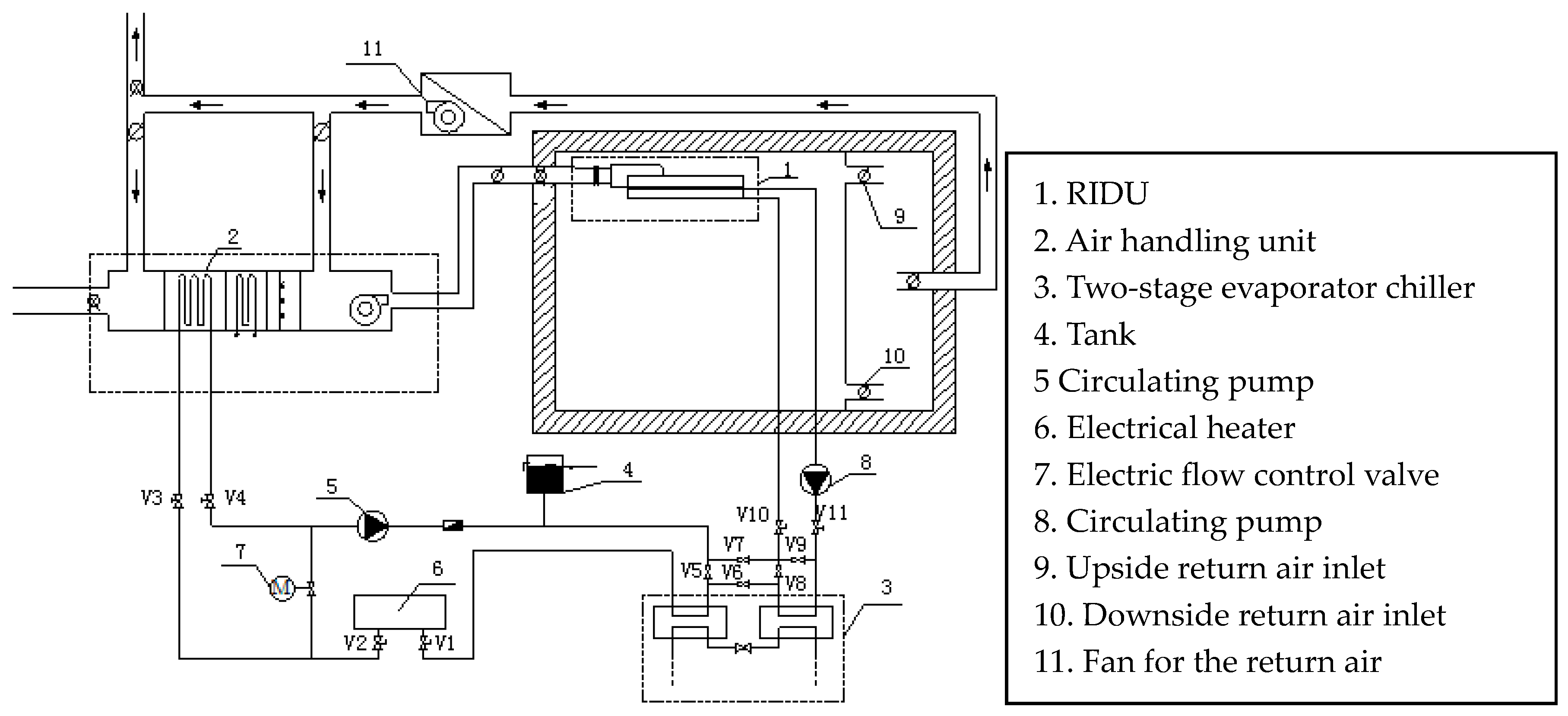
2. The Experimental System

Figure 1 shows the experimental system. The experiments were carried out in a climatic chamber (8.5 m (d) × 8 m (w) × 2.6 m (h)) in which the system was installed. The climatic chamber is located within a large conditioned laboratory. The chamber has one window. The walls, ceiling, and floor have similar construction and thermal properties.
Figure 2 shows the indoor RIDU terminal device, the area of which is 6 m2. Eight RIDUs were installed and controlled, respectively, to run and stop. The operation characteristics were studied when the RIDUs were operating and kept the indoor temperature stable. The prototype of the RIDU was the modified induction unit, the structure of which was manufactured with the corresponding processing. The induction unit was processed to be combined with the aluminum pore radiant panel on which the copper pipes with rigid aluminum diffusion fins were installed. Therefore, the pore radiant panels of the RIDUs can be cooled and heated by both water and air. In the air-type, which is different with the traditional radiant air-conditioning system and mainly studied in this paper, the indoor air is induced and mixed with the primary air. Then the mixed air is blown into the chamber after exchanging heat with the panel.
The temperature of the primary air was controlled by the current signal output from the radiation temperature sensor (accuracy: ±0.38%) which is installed in the center of the chamber at the different heights. Since the primary air supply volume decreases as the temperature difference between the primary air and the chamber increases, it can reduce the energy consumption and the noise for supplying the air to utilize the low primary air temperature. The two-stage evaporator chiller with the non-azeotropic mixture refrigerant was utilized to meet the RIDUs and the air handling unit. The chiller utilizes a mixture of refrigerant of R32/R236fa [13], the mixture ratio of which is 55/45 [13,14,15]. The lowest and highest temperature of the chilled water can reach 7 °C and 17 °C, respectively. The ducts and the RIDUs are covered by polyethylene and rubber, which have thermal-and damp-proof insulation performance because of the closed-cell foam to prevent condensation. To supply primary air with low temperature, the two evaporators can operate in series mode. Additionally, the two evaporators can operate in parallel mode to supply fluid to both the RIDU and the air handling unit.

3. Study of the Induction Characteristics

For the RIDU, the induction ratio is an important parameter. However, there is no dedicated study yet for such a type of terminal unit. However, there has been some research on the entrainment effect which can be incorporated into the modeling. The turbulent merging confined jet phenomenon which happens in the RIDU is very complicated, combined with the structure of the RIDU. In many cases, it is studied with the assistance of computational fluid dynamics (CFD) software (http://www.ansys.com/Products/Fluids/ANSYS-Fluent) and massive experiments [16,17,18,19,20]. To study the induction characteristics of the RIDU, we utilized Fluent 6.3 (ANSYS, Inc., Pittsburgh, PA, USA) to build the model of the RIDU and calculate the operating parameters with different induction ratios.

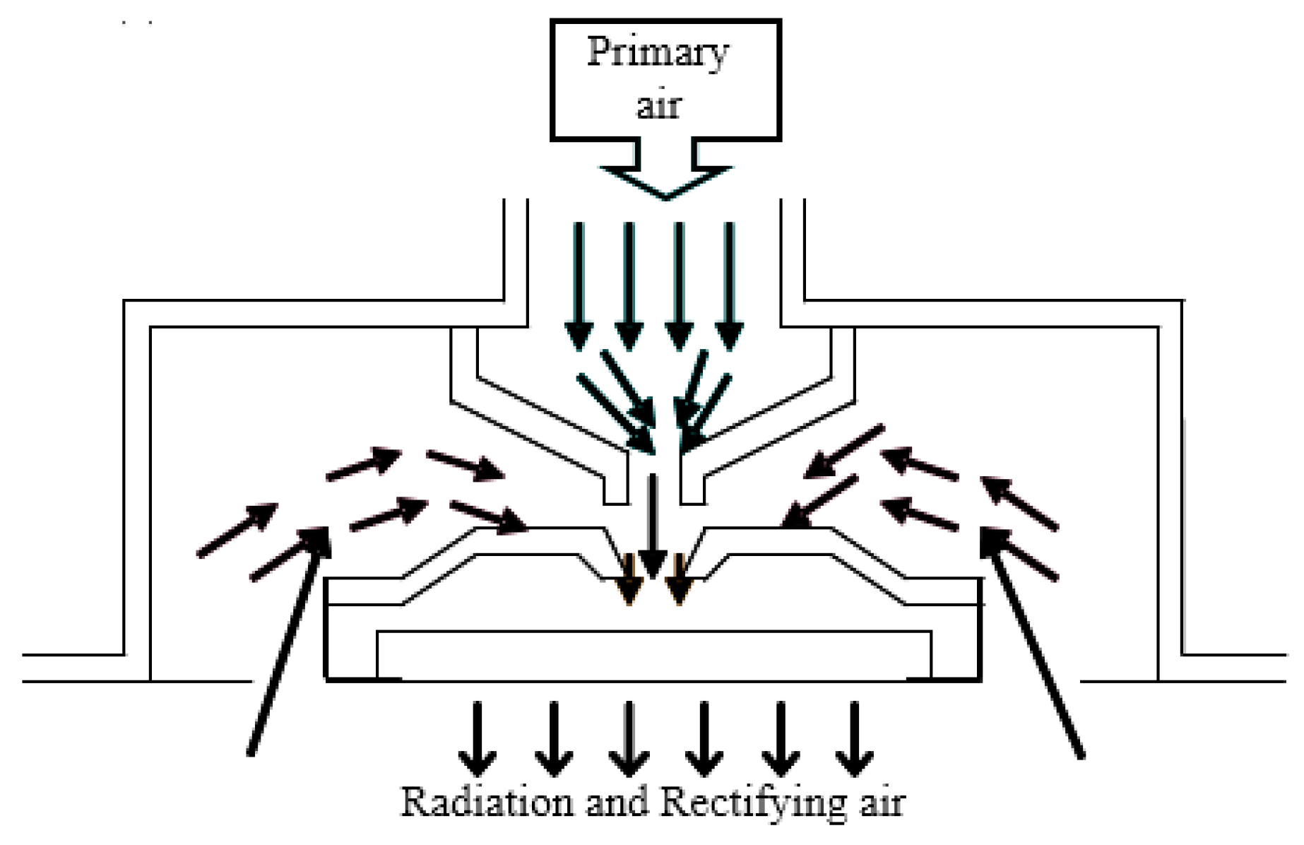
3.1. Model of the Radiant Induction-Unit

As shown in the cross-section of the RIDU in Figure 2, the primary air from the air handing unit was blown into the mixing zone of the RIDU with the nozzle. The negative pressure was created between the nozzle and the inlet of the mixing zone. The indoor return air was inducted into the mixing zone and mixed with the primary air. Then the mixed air exchange heat with the pore radiant panel and passed through the pores of the radiant panel into the chamber. When the simulation proceeded, the primary air temperature can be as low as 7 °C and the inducted return air temperature is 25 °C. Two types of operating conditions were simulated: (1) the supply air velocity and temperature of the nozzle were kept constant. The temperature and volume flow rate of the mixed air were calculated with different sizes of the induction return air inlet and pores; and (2) the physical dimension of the RIDU, the size of the pores, and the primary supply air temperature were kept constant. The temperature and volume flow rate of the inducted return air and the supply air of the pores were calculated with different supply air velocities of the nozzle. In both conditions the induction ratio was calculated and the relationship between it and other parameters was studied. There were three cases, numbered 1, 2 and 3, in the first condition. Three types of models of the RIDUs, labeled A, B and C, were built. In the second condition two cases, numbered 4 and 5, were added and utilized the same model of the RIDU as Case 3. The parameters of the supply air and the model of the RIDU in the five cases are shown in Table 1.

3.2. Mathematical Model

The flow condition of the supply air of the induction radiant air-conditioning system proposed in this paper was the turbulent flow. Thus, the turbulent flow model was utilized in the simulation. It was assumed that the influences of the air leak of the equipment were not considered; the fluid flow of the system was the steady state flow; the flow field had a high Reynolds number; the fluid had isotropic turbulent viscosity; the Boussinesq approximation was met, so the studied fluid was considered incompressible and the variation of its density only affected the buoyancy. In this paper the k ε two-equation models were utilized as the models, which were suitable for simulating the turbulent flow. In the models, the turbulence energy G and the dissipation rating ε were expressed by the following equations. In the equations: G 1 ε = 1.44 ; G 1 ε = 1.44 ; G 3 ε = 0.09 ; P r k = 1.0 ; P r ε = 1.3 .
ρ d k d t = x i [ ( μ + μ t σ k ) ] + G k + G b ρ ε Y M
ρ d ε d t = x i [ ( μ + μ t σ ε ) ε x i ] + G 1 ε ε k ( G k + G 3 ε G b ) G 2 ε ρ ε 2 k
μ = ρ C μ k 2 ε

3.3. Results and Discussion

As shown in Table 2, from the data of Case 3, 4, and 5, it can be found that when the velocity and the volume flow rate of the primary air increase, more indoor return air can be induced. However, the variations of the proportional relationship are minimal when the primary air velocity is in a certain extent. According to the literature [21,22], for the jet flow blown from the nozzle, when the primary air flow rate achieves a certain amount defined as the characteristic primary air flow rate in this paper, the induction ratio will remain constant. To achieve the stable induction ratio, we utilized the relatively high airflow rate. When the primary air flow rate is too low, part of the primary air will flow out from the return air inlet directly because of the gravity and little return air will be inducted which will degrade the performance of the RIDU. Compared to the chilled beam [23,24,25,26,27,28], because the mixed air will exchange heat with the radiant panel, the induction ratio cannot be too high to prevent a reduction in the temperature difference between the mixed air and the pore radiant panel. However, a sufficient mixed air flow rate needs to be ensured to maintain a sufficient heat exchange efficiency. Thus, a relatively high primary air flow rate was utilized during the simulation.
From the data of Case 1, 2 and 3, which utilize the different sizes of the induction return air inlet and nozzle, the sizes of the induction return air inlet and pores both influence the induction ratio. The induction ratio increases as the size of the induction return air inlet increases. However, the variation is small. Similarly, the induction ratio increases as the size of the pore increases. Since the area of the pores is small, the resistance to the supply air is greater than the induction return air inlet. Thus, the variations of the size of the pores have greater influence on the induction ratio. The supply air temperature of the pores is affected by the volume flow rates of the primary air and the inducted return air, which means that the supply air temperature of the pores has a direct relationship with the induction ratio. It can be found that when the induction ratio is less than a certain value, the supply air temperature will suddenly fall dramatically. When the supply air temperature is below the indoor air dew point temperature, condensation will occur. Thus, the anti-condensation performance of the RIDU needs to be studied.

4. Study of the Anti-Condensation Performance of the Radiant Induction-Unit

4.1. The Model of the Pore Radiant Panel

As shown in the analysis of Section 3, the pore size of the pore radiant panel installed at the bottom of the RIDU has a great influence on the induction ratio. Therefore, in the cases of which other conditions are constant, the resistance coefficient of the pore radiant panel determines the amount of the mixed air blown into the chamber. While the resistance coefficient is mainly influenced by the opening ratio and thickness of the pore radiant panel. The shape and the amount of the pores have a small influence only on the uniformity of the air supply when the pores are evenly distributed [29]. In order to reduce the weight and enhance the heat transfer effect, the pore radiant panel is processed to be as thin as possible. Therefore, the thickness has little influence on the resistance coefficient. In this paper, the size of the pore radiant panel is 1200 mm × 800 mm and the thickness is 4 mm. Table 3 shows three pore sizes and the opening ratio to study. The opening ratio is set as H. It is assumed that all the pores are uniformly distributed and have the same size. The surface emissivity ε k of the pore radiant panel is 0.9. The equation of the opening ratio is:
H = A A r A = A o A

4.2. Mathematical Model

In this paper, Gambit (ANSYS, Inc., Pittsburgh, PA, USA) was utilized to build the model of RIDUs and the chamber. Gambit is a software package designed to help analysts and designers build and mesh models for CFD and other scientific applications. It receives user input by means of its graphical user interface (GUI). The GUI makes the basic steps of building, meshing, and assigning zone types to a model simple and intuitive, yet it is versatile enough to accommodate a wide range of modeling applications [30]. The local refinement was carried out for the mesh of the areas of the pores, the primary air inlet and the induction return air inlet. The pores were set as velocity-inlets and the inducted return was set as free outflow. Four air supply velocities (7, 10, 13, 16 m/s) and five air supply temperatures (6, 8, 10, 12, 14 °C) were chosen for the primary air. The relative humidity of the primary air was 95% and the dew point air supply was utilized. By adding indoor sources of heat and humidity, referred to as thermal manikins, which can be controlled with a digital silicon-controlled rectifier [30,31], into the chamber, when the indoor thermal environment parameters became stable, they were controlled to achieve the indoor design parameters of comfort air-conditioning in summer (temperature: 28 °C, relative humidity: 65%). In this condition, the status and the condensation area of the pore radiant panel were studied.
The primary air has a low temperature and was mixed with the inducted return air by the pressure difference of the nozzle. The near-wall jet and the orifice jet are contained in the process. Thus, the pressure-based solver was utilized to solve the momentum equation, the component transport equation, the continuity equation, and the energy equation. The k-ε two-equation models were utilized and the S2S model was utilized for the radiative transfer.

4.3. Results and Discussion

The critical dew-point temperature is defined as the highest temperature which can course the condensation over the pore radiant panel with a certain opening ratio and parameters of the air supply and indoor thermal environment. In this paper, the velocity and temperature of the primary air are the important control parameters for the system. Thus, in adding the opening ratio, its influence to the critical dew-point temperature is studied.

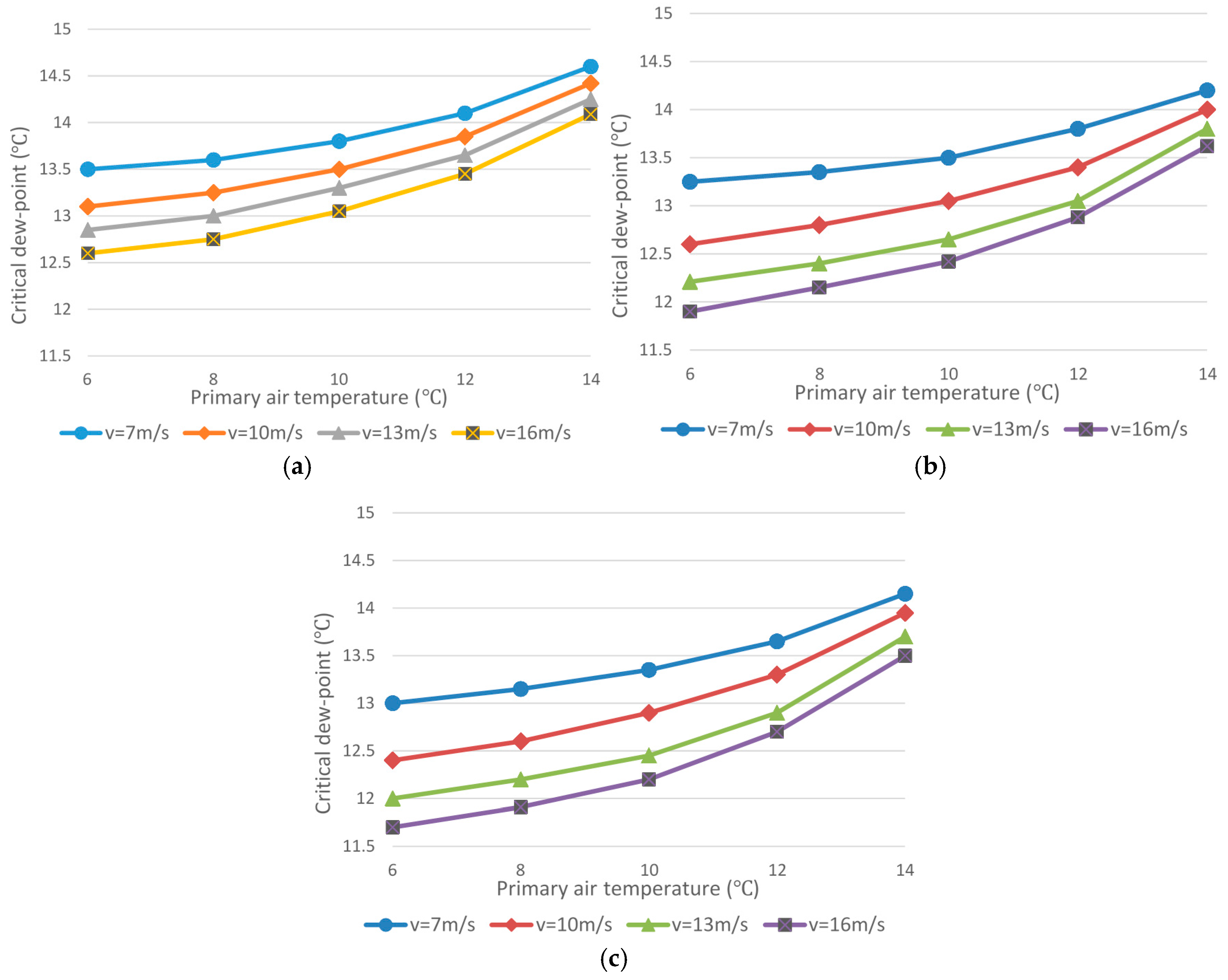
4.3.1. The Primary Air Temperature and the Critical Dew-Point Temperature

As shown in Figure 3, with the increase of the primary air temperature, the critical dew-point temperature increases and shows an accelerated growth trend. The differences between the critical dew-point temperatures of different primary air velocities tend to decrease. This is because the moisture content of the primary air from the air handing unit increases as the temperature increases. When the other conditions are constant, the relative humidity of the mixed air layer between the panel and the indoor air increases as the moisture content of the primary air increases which causes the dew-point temperature to rise rapidly. Meanwhile, the air velocity also influences the dew-point temperature. Due to the increase of the air velocity, the static pressure uniformity in the mixing zone decreases. The moisture content of the mixed air cannot distribute evenly in time which causes the humidity of part of the area near the panel to increase rapidly. Thus, with the same opening ratio, the higher the primary air velocity is, the greater the influence the primary temperature has on the dew-point temperature.

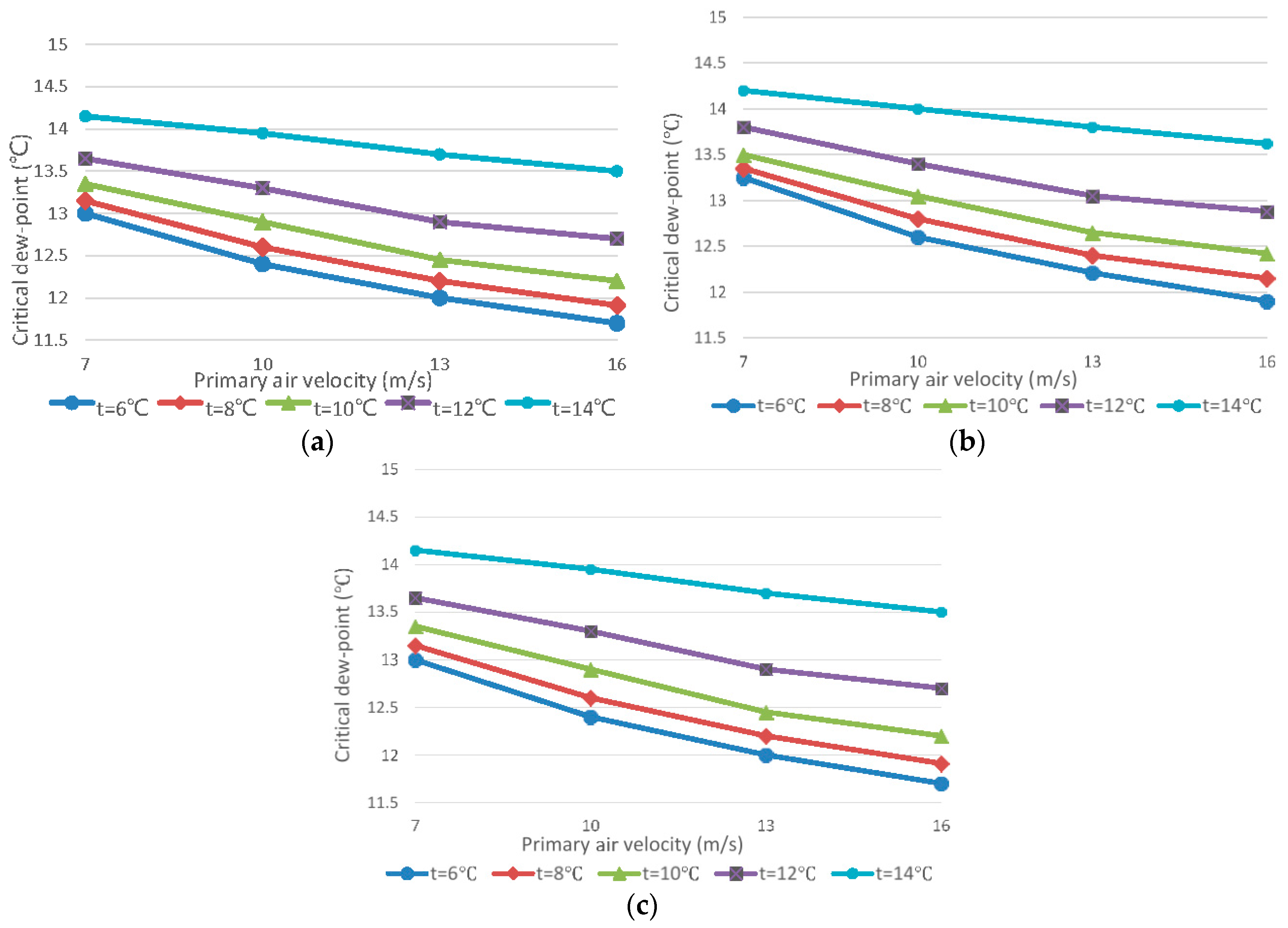
4.3.2. The Primary Air Flow Rate and the Critical Dew-Point Temperature

As the primary air flow rate increases, the static pressure in the mixing zone and the mixed air blown into the chamber increase. Since the moisture content of the mixed air layer decreases, the critical dew-point temperature is lowered. As shown in Figure 4, the dew-point temperature decreases as the primary air flow rate increases. It can also be found that as the primary air temperature increases, the differences between the dew-point temperatures of every air flow rate decrease. Namely, with the increase of the primary air temperature, the influence of the primary air flow rate on the dew-point temperature becomes less.

4.3.3. The Opening Ratio and the Critical Dew-Point Temperature

Table 4 shows the highest and lowest critical dew-point temperatures with different opening ratios. The low-humidity air layer near the pore radiant panel becomes thicker and the critical dew-point temperature become lower as the opening ratio increases. However, the influence of the opening ratio on the dew-point temperature becomes less as the opening ratio increases. From Figure 3 it can also be found that the higher the opening ratio is, the greater influence the primary air temperature and velocity have on the dew-point temperature. It should be paid attention that too high an opening ratio will reduce the heat exchange between the mixed air and the pore radiant panel and increase the air velocity, which affects the comfort.

5. Performance Study of the Radiant Induction-Unit

From the analysis of Section 4, the mixed air enters the chamber though the pores and forms an air layer between the indoor air and the panel, the temperature of which is close to the panel. Thus, the problem of condensation can be effectively solved. Furthermore, relative to the traditional plate-type radiant terminal, the heat transfer of the mixed air is added to the total effective heat transfer of the terminal. Therefore, the analysis of the radiant heat transfer of the RIDU is different from the traditional plate-type radiant terminal. It is necessary to do further analysis based on the characteristics of the RIDU and the radiation heat transfer theory.

5.1. Mathematical Model

Since there are pores on the radiant panel of the RIDU, the relationship between the angle factor and the opening ratio of the pore radiant panel needs to be reconfirmed.
There are plenty of pores on the panel and the pores are small and uniformly distributed. Moreover, the angle factor is a pure geometry and only depends on the size of the surface and the relative position. Therefore, the angle factor can be calculated according to the following equation:
X n , o p = ( 1 H ) X n , f
The angle factor of the whole pore radiant panel can be calculated according to the following equation:
X t , o p = ( 1 H ) X n , p
When the pore radiant panel is divided into numerous parts the area of which are expressed with   d A . Then: X d A , t = 1 .
The heat transfer of the per unit area of the pore radiant panel can be calculated according to the following equation:
Q r , c = Q d A , c A = σ b [ ( t p + Δ t + 273 ) 4 ( t p + 273 ) 4 ] 1 ε o p ε o p d A + 1 X t , d A A t + 1 ε t ε t A t A = ( 1 H ) σ b [ ( t p + Δ t + 273 ) 4 ( t p + 273 ) 4 ] 1 ε o p ε o p + 1 X t , d A
According to the model simplification method of the radiant panel provided by the literature [32], the above equation can be simplified as:
Q r , t h , c = 5.477 ( 1 H ) Δ t
In the general conditions, when the thermal environment of the system and the chamber remain constant, the temperature difference between the radiant panel and the surface of the envelopes is not more than 20 °C. Based on this condition, the maximum relative errors between the simplified and the complete models are less than 6%.

5.2. Experimental Analysis

5.2.1. Validation of the Calculation Method

Although the calculation method proposed in Section 5.1 is simple, it is necessary to verify the accuracy via the experimental method. When the thermal environment of the chamber reaches the stable state, the environmental parameters remain constant. The instantaneous heat exchange between the RIDU and the chamber consists of three parts: (1) the radiant heat exchange between the pore radiant panel and the surface of the envelopes Q r , e x p , c ; (2) the convective heat exchange between the pore radiant panel and the indoor air Q c o n , c ; and (3) the heat exchange between the indoor environment and the mixed air blown into the chamber through the pores Q t h , c . In the steady state, the sum of the three is equal to the heat exchange between the building envelopes and the outdoor environment Q t , c . The heat balance equation is:
Q r , e x p , c = Q t , c Q c o n , c Q t h , c
The instantaneous heat transfers in the steady-state condition can be calculated by substituting the experimental data measured into the corresponding equations. According to the heat balance Equation (9), the actual value of the radiant heat exchange can be calculated and compared with the theoretical value Q r , t h , c calculated with Equation (8).

5.2.2. Calculation of the Convective Heat Exchange

The convection heat exchange can be calculated as [33]:
Q c o n , c = h c Δ t A r = 0.134 ( t h p t a ) 1.25 ( 1 H ) A
Since the mixed air can form an air layer, the temperature of which is close to the panel, the convection heat transfer between the panel and the indoor air caused by the thermal buoyancy is reduced. Therefore, although the convection heat exchange is difficult to be calculated accurately, it can be seen that the value is much less than that of the traditional plate-type radiant panel.

5.2.3. Calculation of the Heat Exchange though the Building Envelopes

The instantaneous heat exchange between the building envelopes and the outdoor environment can be calculated as [34]:
Q t , c = h n A n ( t a t e n )
The parameters of the building envelopes are shown in Table 5. During the experiments, we set 10 temperature measuring points with the PT100 thermocouples (OMEGA Engineering, Inc., Stamford, CT, USA) on every envelope and utilize the average value to calculate Q t , c .

5.2.4. Calculation of the Heat Exchange between the Indoor Environment and the Mixed Air

In the steady-state condition, because the mixed air has fully exchange heat with the pore radiant panel, according to the experimental data the difference between the mixed air and the panel is small (less than 0.6 °C). Therefore, in order to simplify the calculation, it is assumed that the temperature of the mixed air is the same as the pore radiant panel. The mixed air contains the primary air and the induced air. The flow rate of the primary air is accurately measured by air flow sensors (accuracy: ±0.3%) installed in the small-diameter duct between the air handing unit and the chamber. The flow rate of the induced return air is measured by TES-1340 hot-wire anemometer (accuracy: ±0.3%) (TES Electrical Electronic Corp., Taipei, Taiwan). The area of the induction return air inlet is averagely divided into 10 parts and the average value is collected. The heat exchange between the mixed air and the indoor environment can be calculated as:
Q t h , c = 1010 ρ G m ( t a t m )

5.3. Results and Discussion

All of the eight RIDUs were operating during the experiments. The area of every RIDU is 6 m2. The opening ratios of the RIDUs chosen for the experiments are 3%, 6% and 9%. The volume flow rate and the temperature of the primary air was 652.50 m3/h and 13 °C, respectively. The primary air flow rate to every RIDU was controlled by the air volume control valves TVR-Easy250 (TROX GmbH, Neukirchen-Vluyn, Germany) [35]. All of the experimental data are recorded under steady-state. The attention is focused on the stabilization of the induced return air volume flow rate which is the difficulty of the experiments. The micromanometer reading for the induced return air is valid only if its variation is within ±10 L/h for 5 m. When the steady state of the volume flow rate and the temperature of the primary air and the thermal environment of the chamber is confirmed, the heat exchanges calculated with the methods in Section 5.1 and Section 5.2, separately, are shown in Table 6.
From the data in Table 6 it can be found that the actual value of the theoretical value calculated with Equation (8) is less than 3%. Therefore, the simplified model is suitable for the performance evaluation of the RIDU under certain conditions.
The radiant heat exchange of the pore radiant panel decreases as the opening ratio increases. This is because the radiating area is reduced. However, on the other hand, the one-way resistance is reduced, which increases the primary air velocity and the inducted return air. Thus, the total volume of the mixed air which exchange heat with the panel increases. Therefore, although the heat transfer area between the mixed air and the pore radiant panel decreases, the reduction of the radiant heat transfer is small. The increasing of the inducted return air reduces the temperature difference between the mixed air and the indoor environment. However, increasing the total volume of the mixed air also increases the total heat exchange of the RIDU, which equals the heat exchange between the building envelopes and the outdoor environment. Ultimately the air-condition load removed by the RIDUs increases as the opening ratio increases. Overall, the higher the opening ratio is, the more the RIDU approximates to the traditional air conditioner. When the opening ratio is too high, the advantages of the radiant air-conditioning cannot be maximized.
Figure 5 illustrates the comparison between the RIDUs with the different opening ratios and the traditional plate-type metal ceiling radiant panels operating in the same condition. It can be seen that the radiant and the convection heat exchanges of the metal ceiling radiant panels are more than that of the RIDU. However, in the total heat exchange of the RIDU, the heat exchange between the mixed air and the indoor air is added and occupies the proportion of 23.4%, which increases as the opening ratio increases. According to the calculated result, the total heat exchange of the RIDU is 16.5% more than that of the metal ceiling radiant panel with the same equipment distribution area.

6. Conclusions

In this paper, the induction radiant air-conditioning system was proposed. The experiments were carried out and the relationship between the induction ratio of the RIDU and the characteristics of the air supply were studied. Based on this, the anti-condensation performance, characteristics of radiation, and convection heat transfer of the RIDU were studied.
The induction ratio of the RIDU is influenced by the structure and the primary air velocity. As the increasing of the primary air velocity, the induction ratio tends to be stable. The induction ratio increases as the sizes of the nozzle and the pores increase, but the pores that have higher resistance have greater influence. Too low an induction ratio will cause condensation.
(1)
The critical dew-point temperature increases as the primary air temperature increases and decreases as the primary air velocity and the opening ratio increases. The opening ratio also influences the variation trend of the critical dew-point temperature. When the opening ratio of the pore radiant panel is 9%, the highest critical dew-point temperature of the RIDU can reach 15.1 °C, which is lower than 20.8 °C of the traditional plate type metal ceiling radiant panel with the same indoor temperature and humidity (28 °C, 65%). Therefore, the induction radiant air-conditioning system has better anti-condensation performance and more extensive applicability. The temperature of the primary air and the chilled water can be lowered to reduce the energy consumption, cooperating with the two-stage evaporator chiller.
(2)
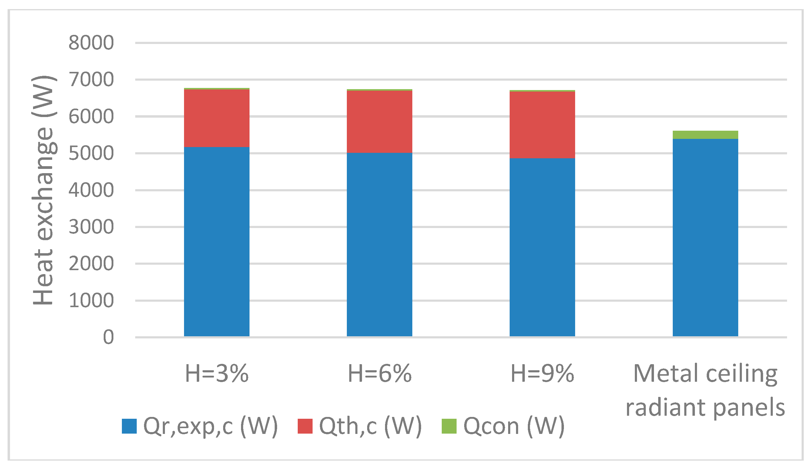
Based on the radiation heat transfer theory, the heat transfer characteristics of the RIDU are studied. The calculation error of the simplified model built for calculating the radiant heat exchange was 3%. As the opening ratio of the pore radiant panel increases, the radiant heat exchange decreases and the air supply heat exchange and its proportion increases. The total heat exchange of the RIDU slightly increases. With the primary air the flow rate and temperature of which are 652.50 m3/h and 13 °C, respectively, in the same condition, and the total heat exchange of the RIDU is 16.5% more than that of the traditional plate-type radiant panel.

Acknowledgments

The authors acknowledge the support of National Key Research and Development Program of China (Grant No. 2016YFC0700303).

Author Contributions

Qiang Si and Xiaosong Zhang conceived and designed the experiments; Qiang Si performed the experiments; Qiang Si analyzed the data; Xiaosong Zhang contributed analysis tools; Qiang Si wrote the paper.

Conflicts of Interest

The authors declare no conflict of interest.

Nomenclature

b buoyancy, N
G turbulence energy, W
Y M coefficient of the compressible turbulent flow pulsation to the total dissipation rate
A total area of the pore radiant panel, m2
A r actual radiation area of the pore radiant panel, m2
A h total area of the pores, m2
H opening radio
t temperature, °C
v air flow rate, m/s
Q heat exchange, W
X n , o angel factor of the No.   n surface of the pore radiant panel
X n , f angel factor of the No.   n surface of the plate type radiant panel
P r Prandtl number
G m mixed air flow rate, m3/s
Greek Letters
ε dissipation rating
μ turbulent viscosity, Pa
σ b Boltzmann constant
Subscript
k average velocity gradient, s−1
t total
c cooling
p panel
n node
o pore
o p pore panel
c o n convection
t h thermal
e x p experiment
a ambience
e n envelope
mmixed air

References

  1. Bojić, M.; Cvetković, D.; Skerlić, J.; Nikolić, D.; Boyer, H. Performances of low temperature radiant heating systems. Energy Build. 2013, 61, 233–238. [Google Scholar] [CrossRef]
  2. Takaho, I.; Hirohumi, H.; Masamichi, E.; Hiroshi, S.; Hiroshi, Y. Experimental Study on Performance Evaluation of the Ceiling Radiant Cooling System: Part 2 Comparison between Ceiling Radiant Cooling System and Convection Cooling System in Physiological and Psychological Reaction at the Time of Awaking. In Summaries of Technical Papers of Annual Meeting Architectural Institute of Japan; Architectural Institute of Japan: Tokyo, Japan, 2006. [Google Scholar]
  3. Takanori, M.; Gyuyoung, Y.; Hideki, T.; Hiroshi, S. Study on the Air-conditioning System Coupling Convection with Radiation by Using Foraminate Ceiling Panel: Part 1 Verification of System Effectiveness by the Experiments. In Summaries of Technical Papers of Annual Meeting Architectural Institute of Japan; Architectural Institute of Japan: Tokyo, Japan, 2007. [Google Scholar]
  4. Mumma, S.A. Chilled ceilings in parallel with dedicated outdoor air systems: Addressing the concerns of condensation, capacity, and cost, american society of heating, refrigerating and air-conditioning engineers. ASHRAE Trans. 2002, 108, 220–231. [Google Scholar]
  5. Oxizidis, S.; Papadopoulos, A.M. Performance of radiant cooling surfaces with respect to energy consumption and thermal comfort. Energy Build. 2013, 57, 199–209. [Google Scholar] [CrossRef]
  6. Feng, J.; Schiavon, S.; Bauman, F. Cooling load differences between radiant and air systems. Energy Build. 2013, 65, 310–321. [Google Scholar] [CrossRef]
  7. Cholewa, T.; Rosiński, M.; Spik, Z.; Dudzińska, M.R.; Siuta-Olcha, A. On the heat transfer coefficients between heated/cooled radiant floor and room. Energy Build. 2013, 66, 599–606. [Google Scholar] [CrossRef]
  8. Yang, C.M.; Chen, C.C.; Chen, S.L. Energy-efficient air conditioning system with combination of radiant cooling and periodic total heat exchanger. Energy 2013, 59, 467–477. [Google Scholar] [CrossRef]
  9. Gao, Z.H.; Liu, X.H.; Yi, J. Experiment study on cooling capacity of capillary-tube radiation air-conditioner. Acta Energiae Solaris Sin. 2011, 32, 101–106. [Google Scholar]
  10. Dai, Y.; Wang, R. New Development and Perspective of Solar Air Conditioning and Cooling Technology. J. Chem. Ind. Eng. 2008, 59, 1–8. [Google Scholar]
  11. Khan, Y.; Khare, V.R.; Mathur, J.; Performance, M.B. Evaluation of radiant cooling system integrated with air system under different operational strategies. Energy Build. 2015, 97, 118–128. [Google Scholar] [CrossRef]
  12. Si, Q.; Zhang, X.S. Performance evaluation and experimental study of the induction radiant air-conditioning system. Procedia Eng. 2015, 121, 1795–1804. [Google Scholar] [CrossRef]
  13. Liu, J.; Zhang, X.S. Performance analysis of a novel double-temperature chilling water unit using large temperature glide zeotropic mixture. Procedia Eng. 2015, 121, 1222–1229. [Google Scholar] [CrossRef]
  14. Liu, J.; She, X.H.; Zhang, X.S.; Man, L.; Zhou, W. Experimental study of a novel double temperature chiller based on R32/R236fa. Energy Convers. Manag. 2016, 124, 618–626. [Google Scholar] [CrossRef]
  15. Liu, J.; She, X.H.; Zhang, X.S.; Cong, L.; Man, L.; Lindeman, B.; Lin, T. Experimental and theoretical study on a novel double evaporating temperature chiller applied in THICS using R32/R236fa. Int. J. Refrig. 2016, in press. [Google Scholar] [CrossRef]
  16. Xu, X.; Zhang, X. Numerical simulation of air quantity and pressure drop performance of perforated supply air terminals. Refrig. Technol. 2009, 2, 34–37. [Google Scholar]
  17. Wang, H.; Davidson, M. Jet interaction in a still ambient fluid. J. Hydraul. Eng. 2003, 129, 349–357. [Google Scholar] [CrossRef]
  18. Morton, B.R.; Taylor, G.; Turner, J.S. Turbulent gravitational convection from maintained and instantaneous sources. Proc. R. Soc. Lond. A 1956, 234, 1–23. [Google Scholar] [CrossRef]
  19. Enjalbert, N.; Galley, D.; Pierrot, L. An entrainment model for the turbulent jet in a coflow. Comptes Rendus Mec. 2009, 337, 639–644. [Google Scholar] [CrossRef]
  20. Wang, H.J. Jet Interaction in a Still or Co-Flowing Environment. Ph.D. Thesis, Hong Kong University of Science and Technology, Hong Kong, China, 2000. [Google Scholar]
  21. Hodgson, J.E.; Moawad, A.K.; Rajaratnam, N. Concentration field of multiple circular turbulent jets. J. Hydraul. Res. 1999, 37, 249–256. [Google Scholar] [CrossRef]
  22. Zhang, Z.L.; Zhang, X.; Zhang, E.Z. Experiment of induction ratio of the diffuser with nozzles. Heat. Vent. Air Cond. 2008, 38, 62–64. [Google Scholar]
  23. Chen, C.; Cai, W.J.; Giridharan, K.; Wang, Y.Y. A hybrid dynamic modeling of active chilled beam terminal unit. Appl. Energy 2014, 128, 133–143. [Google Scholar] [CrossRef]
  24. Koskela, H.; Häggblom, H.; Kosonen, R.; Ruponen, M. Air distribution in office environment with asymmetric workstation layout using chilled beams. Build. Environ. 2010, 45, 1923–1931. [Google Scholar] [CrossRef]
  25. Ahmed, K.; Kurnitski, J.; Sormunen, P. Demand controlled ventilation indoor climate and energy performance in a high performance building with air flow rate controlled chilled beams. Energy Build. 2015, 109, 115–126. [Google Scholar] [CrossRef]
  26. Chen, C.; Cai, W.J.; Wang, Y.Y.; Lin, C. Further study on the heat exchanger circuitry arrangement for an active chilled beam terminal unit. Energy Build. 2015, 103, 352–364. [Google Scholar] [CrossRef]
  27. Guan, Z.M.; Wen, C.Y. Geometric optimization on active chilled beam terminal unit to achieve high entrainment efficiency. Appl. Therm. Eng. 2016, 98, 816–826. [Google Scholar] [CrossRef]
  28. Nelson, I.C.; Culp, C.H.; Rimmer, J.; Tully, B. The effect of thermal load configuration on the performance of passive chilled beams. Build. Environ. 2016, 96, 188–197. [Google Scholar] [CrossRef]
  29. Fluent, Inc. Gambit User’s Guide 2007; ANSYS, Inc.: Pittsburgh, PA, USA, 2007. [Google Scholar]
  30. Chludzinska, M.; Mizielinski, B.; Bogdan, A. Application of the thermal manikin for ventilation and air-conditioning system assessment. Environ. Eng. 2010, 3, 121–126. [Google Scholar]
  31. Wu, W.Q.; Lin, Z. Experimental study of the influence of a moving manikin on temperature profile and carbon dioxide distribution under three air distribution methods. Build. Environ. 2015, 87, 142–153. [Google Scholar] [CrossRef]
  32. Kilkis, L.B.; Sager, S.S.; Uludag, M. A simplified model for radiant heating and cooling panels. Simul. Pract. Theory 1994, 2, 61–76. [Google Scholar] [CrossRef]
  33. Min, T.C.; Schutrum, L.F.; Parmelee, G.V. Natural convection and radiation in a panel heated room. ASHRAE Trans. 1956, 62, 337–358. [Google Scholar]
  34. Lu, Y.Q. Practical HVAC Design Manual; China Architecture & Building Press: Beijing, China, 2008. [Google Scholar]
  35. TROX Ltd. TROX TVR-Easy User’s Guide 2016; TROX GmbH: Neukirchen-Vluyn, Germany, 2016. [Google Scholar]
Figure 1. The experimental system. RIDU: Radiant induction-unit.
Energies 10 00026 g001
Figure 2. Cross-section of the RIDU.
Energies 10 00026 g002
Figure 3. The primary air temperature and the critical dew-point temperature: (a) H = 3%; (b) H = 6%; and (c) H = 9%.
Energies 10 00026 g003
Figure 4. The primary air velocity and the critical dew-point temperature: (a) H = 3%; (b) H = 6%; and (c) H = 9%.
Energies 10 00026 g004
Figure 5. The comparison between the RIDUs (6 × 8 m2) and the traditional plate-type radiant panel.
Energies 10 00026 g005
Table 1. The parameters of the supply air and the model of the RIDU.
CaseModel NumberSize of the Induction Return Air InletSize of the PorePrimary Supply Air Flow Rate (m3/h)
Length (mm)Width (mm)Length (mm)Width (mm)
1A12009015030652.5
2B160015012030652.5
3C12009012030652.5
4C12009012030471.2
5C12009012030321.9
Table 2. The calculated results of the five cases.
Case12345
The volume flow rate of the primary air (m3/h)652.50652.50652.50471.20321.87
The volume flow rate of the inducted return air (m3/h)421.32342.51341.78230.15133.21
The volume flow rate of the mixed air (m3/h)1073.82995.01994.28701.35455.08
The induction ratio0.640.520.510.480.41
Supply air temperature of the pore radiant panel (°C)18.3115.6115.5714.9113.72
Table 3. The pore size and the opening ratio.
No.123
Opening ratio H (%)369
Pore size (mm)40 × 1080 × 10120 × 10
Table 4. The opening ratio and the critical dew-point temperature.
Opening RatioCritical Dew-Point Temperature
%Highest (°C)Lowest (°C)
315.112.5
613.911.8
913.211.3
Table 5. The parameters of the building envelopes.
EnvelopeHeat Transfer Surface Area (m2)Thermal transmittance (W/m2K)
Southern exterior wall8.82.92
Southern exterior window3.22.5
Southern exterior door3.62.5
Northern interior wall143.92
Northern interior door2.93.5
Eastern interior wall213.92
Western interior wall212.76
Floor663.3
Ceiling583.3
Table 6. The heat exchanges with different opening ratio.
H (%) Q t , c (W) Q t h , c (W) Q r , e x p , c (W) Q r , t h , c (W)
36635155750785202
66703168750165094
96791184949424979

