1. Introduction
AC-AC power conversion systems are widely used in various applications such as renewable energy conversion systems, adjustable speed drives, and AC-AC transmission [
1,
2,
3,
4,
5]. In general, a back-to-back (B2B) converter is used for AC-AC power conversion systems. It consists of a rectifier stage, inverter stage, and DC-link stage as energy storage elements. Therefore, a B2B converter is an AC-DC-AC indirect power conversion system; furthermore, it has disadvantages such as a bulky size and short lifetime because of the DC-link capacitors [
6,
7,
8,
9,
10].
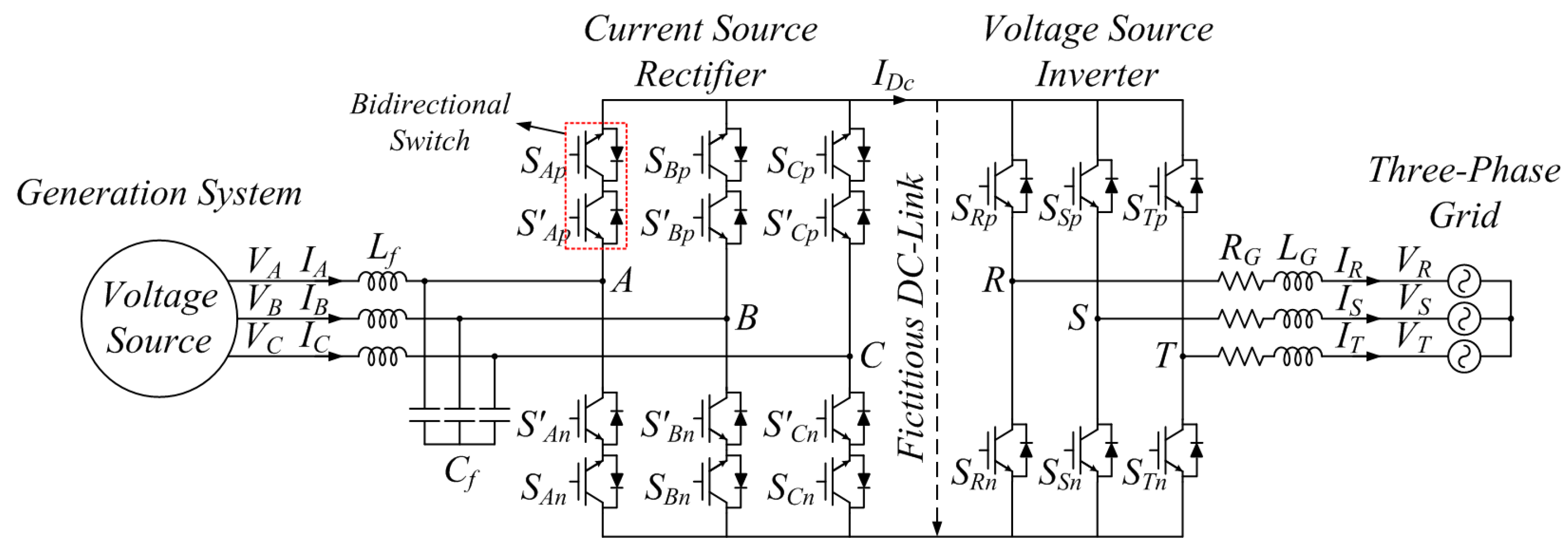
There is another topology for AC-AC power conversion: an indirect matrix converter (IMC). An IMC is structurally similar to a B2B converter; however, unlike the B2B converter, an IMC does not have energy storage elements such as DC-link capacitors. Therefore, an IMC can overcome the disadvantages of a B2B converter caused by the DC-link capacitors. An IMC is composed of a current source rectifier (CSR) stage as the input stage, and a voltage source inverter (VSI) stage as the output stage. It has a fictitious DC-link between the CSR stage and VSI stage. In this regard, the IMC is an AC-AC direct power conversion system, which is called a two-stage matrix converter. It has many advantages such as a compact power circuit and sinusoidal input and output currents under normal conditions [
11,
12,
13,
14,
15]. In general, the CSR stage of the IMC is connected to a three-phase voltage source such as three-phase grid and generation system (GS) using a generator or gas engine.
GSs are widely used in distributed GSs and microgrid systems [
16,
17,
18,
19,
20]. The generator of a GS generates constant three-phase voltages in the normal state. In addition, power generated by the generator is transmitted to the three-phase grid of the output stage through a power conversion system such as a B2B converter or an IMC. In the IMC, if the three-phase grid of the output stage has balanced voltage conditions, the grid archives balanced three-phase currents. However, if the three-phase grid has unbalanced voltage conditions, the input and output currents are affected by the unbalanced grid voltage conditions and are distorted. The distorted currents of the input and output stages increase the torque ripple of the generator in the GS and degrade the power quality of the grid. This results in the instability of the overall system, and affects the life span of the system.
If the three-phase grid connected to the CSR stage of the IMC has unbalanced voltage conditions, the three-phase currents of the CSR stage are distorted. In order to reduce the distortion, the modulation strategies of the IMC under unbalanced voltage conditions of the three-phase grid connected to the CSR stage are researched [
21,
22].
This paper proposes a control strategy for balanced input currents of an AC-AC power conversion system using an IMC under unbalanced grid voltage conditions. Because the IMC does not have DC-link energy storage elements, the currents of the CSR stage are directly transmitted to the three-phase grid connected to the VSI stage. Therefore, under unbalanced grid voltage conditions, the currents of both the CSR stage and VSI stage are distorted. To control the balanced currents of the CSR stage, the power of the VSI stage transmitted from the CSR stage should be a DC value without ripple components because the voltages generated by the generator of the GS have balanced voltage conditions. The unbalanced voltages and currents of the VSI stage are composed of positive and negative phase-sequence components [
23,
24,
25]. In the proposed control strategy, these are decoupled under unbalanced grid voltage conditions. These decoupled components are used to calculate new reference currents for balanced input currents, and the power quality of the grid can be improved using the proposed control strategy. Additionally, the distortion of the VSI stage currents caused by the unbalanced voltage conditions also decreases because of the proposed control strategy. The suitable operation and effectiveness of the proposed control strategy is demonstrated by simulation and experimental results.
3. Proposed Control Strategy for Balancing Currents of Current Source Rectifier Stage under Unbalanced Grid Voltage Conditions
3.1. Control of Indirect Matrix Converter Connected to Three-Phase Grid
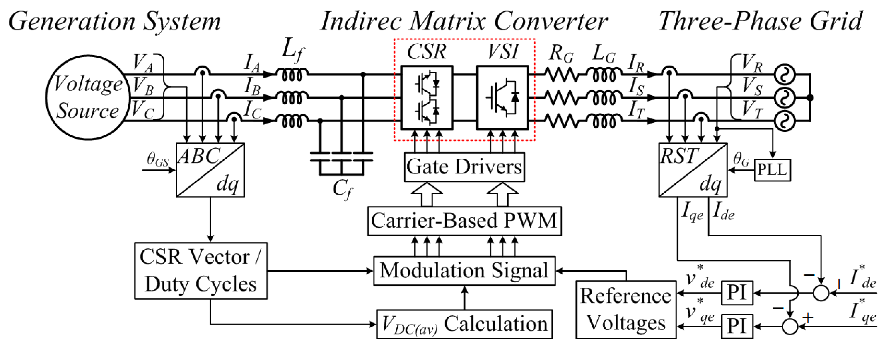
Figure 4 shows a control block diagram of the grid-connected system using the IMC. This system is composed of a GS connected to the CSR stage, and a three-phase grid connected to the VSI stage.
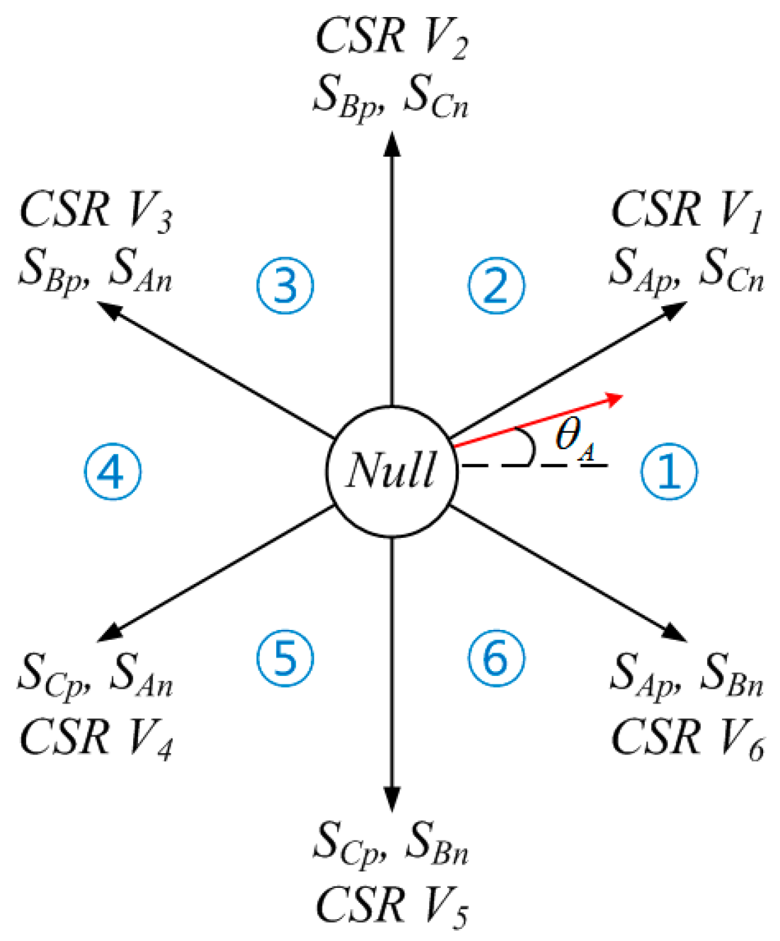
In the CSR stage, VA, VB, and VC generated by the generator of the GS are transformed to a d-q axis synchronous reference frame using a phase angle (θGS), which is obtained from the rotation angle of the generator. The d-q-axis-transformed voltages of the CSR stage are used to select the CSR space vector and to calculate the duty cycles. Lastly, the switches of the CSR stage are operated by a modulation strategy with Equations (1)–(3).
In the VSI stage, a phase angle (θG) of the three-phase grid is generated by the phase-locked loop (PLL) method. The three-phase currents (IR, IS, IT) are transformed to a d-q axis synchronous reference frame using θG. The d-q axis transformed currents (Ide and Iqe) of the VSI stage are controlled to d-q axis reference currents ( and ) using proportional-integral (PI) control. Additionally, vR, vS, and vT (as three-phase reference voltages) are produced by the current control. Lastly, the switches of the VSI stage are operated by the modulation strategy with Equations (4) and (5).
If the three-phase grid has balanced voltage conditions, in the normal state, the currents of the CSR stage and VSI stage are maintained as balanced three-phase currents. However, if the three-phase grid has unbalanced voltage conditions, the three-phase currents (IA, IB, IC) of the CSR stage and IR, IS, and IT of the VSI stage are distorted because the currents of the CSR stage are directly transmitted to the three-phase grid without the DC-link energy storage elements. In this case, an additional control strategy for balancing currents in the CSR stage is required under unbalanced grid voltage conditions because the distorted currents can affect the generator of the GS and decrease the power quality.
In this paper, the currents of the VSI stage are controlled to transmit DC power from the CSR stage to control the balanced currents of the CSR stage. In the proposed control strategy, the positive and negative phase-sequence components from the unbalanced grid voltages and currents are decoupled. In addition, these decoupled components are used to calculate the new reference currents for the positive and negative phase-sequence currents of the VSI stage. The decoupled positive and negative phase-sequence currents of the VSI stage are controlled as the new reference currents. This results in balanced currents in the CSR stage despite the unbalanced grid voltage conditions. Furthermore, the distortion of the VSI stage currents by the unbalanced voltage conditions decreases.
3.2. Decoupling the Positive and Negative Phase-Sequence Components from Unbalanced Grid Voltages and Currents
The unbalanced voltage conditions of the three-phase grid are generated by three-phase voltages with different magnitudes. The unbalanced grid voltages and currents involve the positive and negative phase-sequence components. In this regard, these components can be detected using a method of symmetrical coordinates [
28].
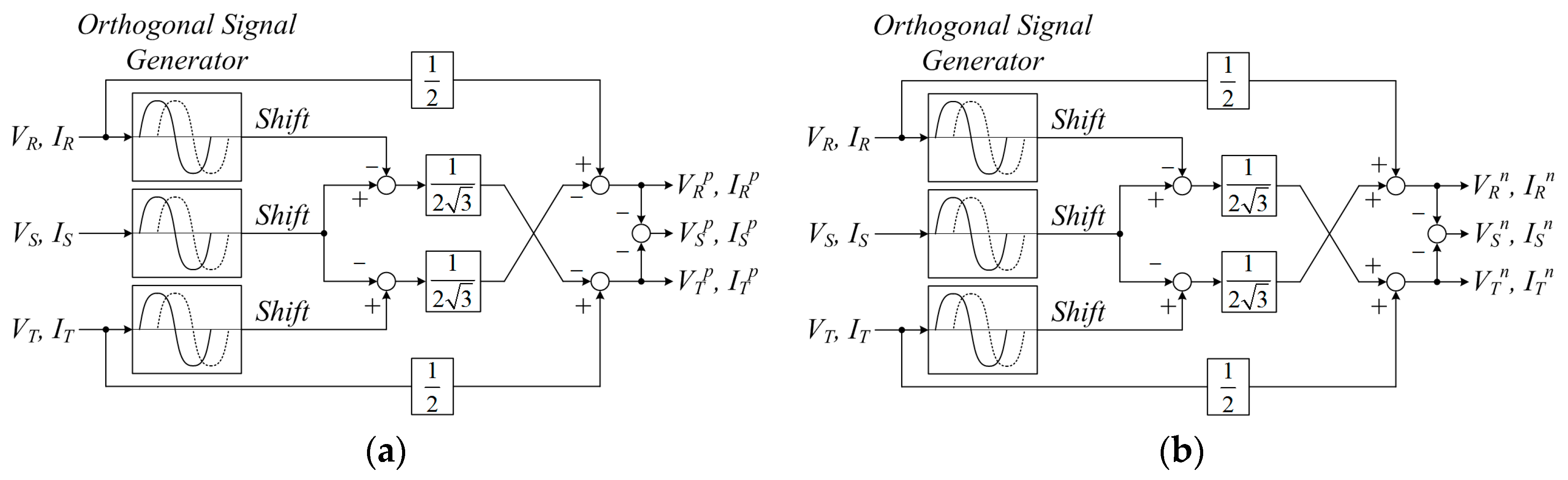
Figure 5 shows the detection method for the positive and negative phase-sequence components from the unbalanced grid voltages and currents. First, 90° phase-shifted voltages and currents are generated by an orthogonal signal generator. The instantaneous values of the positive phase-sequence components (
,
,
,
,
,
) and the negative phase-sequence components (
,
,
,
,
,
) are detected using the voltages and currents (
VR,
VS,
VT,
IR,
IS,
IT) of the three-phase grid with 90° phase-shifted voltages and currents.
3.3. Determination of Reference Currents for Balanced Currents of Current Source Rectifier Stage under Unbalanced Grid Voltage Conditions
In the grid-connected IMC with the GS, if the three-phase grid has unbalanced voltage conditions, the currents of the CSR stage and VSI stage are distorted. Therefore, new reference currents for the balanced currents of the CSR stage are required. In this paper, the detected positive and negative phase-sequence voltages and currents are used for the new reference currents of the VSI stage.
First, an angular frequency (ω) of
,
, and
is generated by the PLL method.
,
, and
, and
,
, and
under the unbalanced grid voltage conditions are transformed to a
d-q axis synchronous reference frame (
and
) using ω. Additionally,
d-q axis negative phase-sequence voltages (
) and currents (
) are transformed using a reverse angular frequency of the ω. In the grid-connected IMC, power generated by the generator of the GS is directly transmitted to the three-phase grid without the energy storage elements. Therefore, under unbalanced grid voltage conditions, the apparent electric power (
S) generated by the generator of the GS can be calculated using
,
,
, and
as in Equation (6).
In addition, active [
P(
t)] and reactive instantaneous power [
Q(
t)] under unbalanced grid voltage conditions are calculated as in Equation (7). They are composed of DC components such as
P0 and
Q0 and AC components such as
Pcos2,
Psin2,
Qcos2, and
Qsin2 vibrating to two times of the grid frequency.
P0 and
Q0 as DC components and
Pcos2,
Psin2,
Qcos2, and
Qsin2 as AC components are represented using
,
,
, and
as synchronous reference frame voltages and currents, as in Equation (8).
From Equation (8), if
Qcos2 and
Qsin2 as AC components of the reactive power are eliminated to obtain balanced currents of the CSR stage through the balanced active power, the parameters of instantaneous power are rearranged in matrix form as in Equation (9). Therefore, the new reference currents are determined by
;
; active reference power such as
P0,
Pcos2, and
Psin2; and
Q0 as the reactive reference power.
Additionally, to eliminate
Pcos2 and
Psin2 as AC components of the active power under unbalanced grid voltage conditions, the reference power values are determined as in Equation (10).
If the reference power values are determined as in Equation (10), from Equation (9), the new reference currents for the balanced currents of the CSR stage under unbalanced grid voltage conditions are determined as in Equation (11). In addition, they are used for the
d-q axis current controller of the VSI stage.
If the
d-q axis reference currents under balanced grid voltage conditions are expressed as
and
, they are indicated as active and reactive average powers, respectively. Therefore, the power references (
and
) are expressed as in Equation (12).
Substituting Equation (12) for Equation (11), the new reference currents for the balanced currents of the CSR stage under unbalanced grid voltage conditions are determined as in Equation (13), which are composed of the positive and negative phase-sequence voltages.
Lastly, and (as decoupled positive and negative phase-sequence currents of the VSI stage) are controlled to new reference currents. In this regard, the new reference currents are calculated for the balanced active power by eliminating the AC components of P and Q under unbalanced grid voltage conditions. Therefore, the proposed control strategy leads to balanced currents of the CSR stage. In addition, the distortion of the VSI stage currents decreases.
4. Simulation Results
A comprehensive simulation study was performed using a Powersim (PSIM) simulation (Powersim Inc., Rockville, MD, USA) to verify the performance of the proposed control strategy for balancing currents of the CSR stage under unbalanced grid voltage conditions. In the simulation, the parameters of the elements in the overall system shown in
Figure 1 are listed in
Table 1.
Additionally, in the simulation, a permanent magnet synchronous generator (PMSG) is used to generate the three-phase voltages. Its parameters are listed in
Table 2.
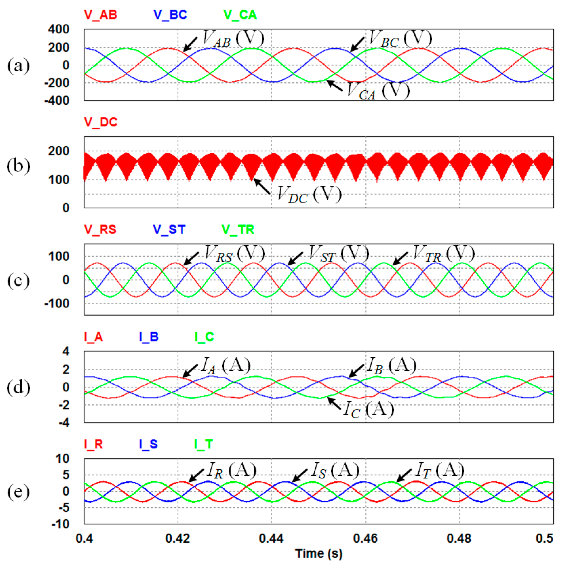
Figure 6 shows simulation results in which the three-phase currents of the VSI stage are controlled to reference current under balanced grid voltage conditions using the IMC. In this case, the PMSG of the GS is rotated at 750 rpm and generates three-phase 37.5-Hz/190-V
peak line-to-line voltages such as
VAB,
VBC, and
VCA.
VDC of the IMC is generated by the maximum and second-largest magnitudes of
VAB,
VBC, and
VCA generated by the PMSG. To produce
VDC, the CSR stage of the IMC is controlled using a modulation strategy. The three-phase grid generates three-phase 60-Hz/50-V
rms line-to-line voltages such as
VRS,
VST, and
VTR. In addition,
IR,
IS, and
IT are controlled to 3 A through the IMC. The three-phase currents of the CSR and VSI stages are generated to balance currents because the three-phase grid has balanced voltage conditions.
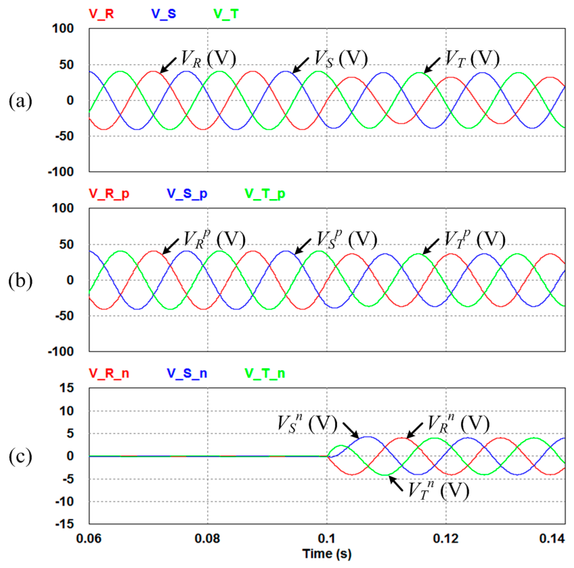
Figure 7 shows simulation results in which the positive and negative phase-sequence voltages of the VSI stage under unbalanced grid voltage conditions are detected. The three-phase grid is changed to unbalanced voltage conditions at 0.1 s from the normal state, with balanced voltage conditions supplying three-phase 60-Hz/50-V
rms line-to-line voltages. In this case, the magnitude of
VR decreases to 70% compared with that of the normal state. Depending on the detection method as shown in
Figure 5,
,
, and
(as the positive phase-sequence voltages) and
,
, and
(as negative phase-sequence voltages) are detected under unbalanced grid voltage conditions. These detected values are used to calculate the new reference currents for the positive and negative phase-sequence currents of the VSI stage.
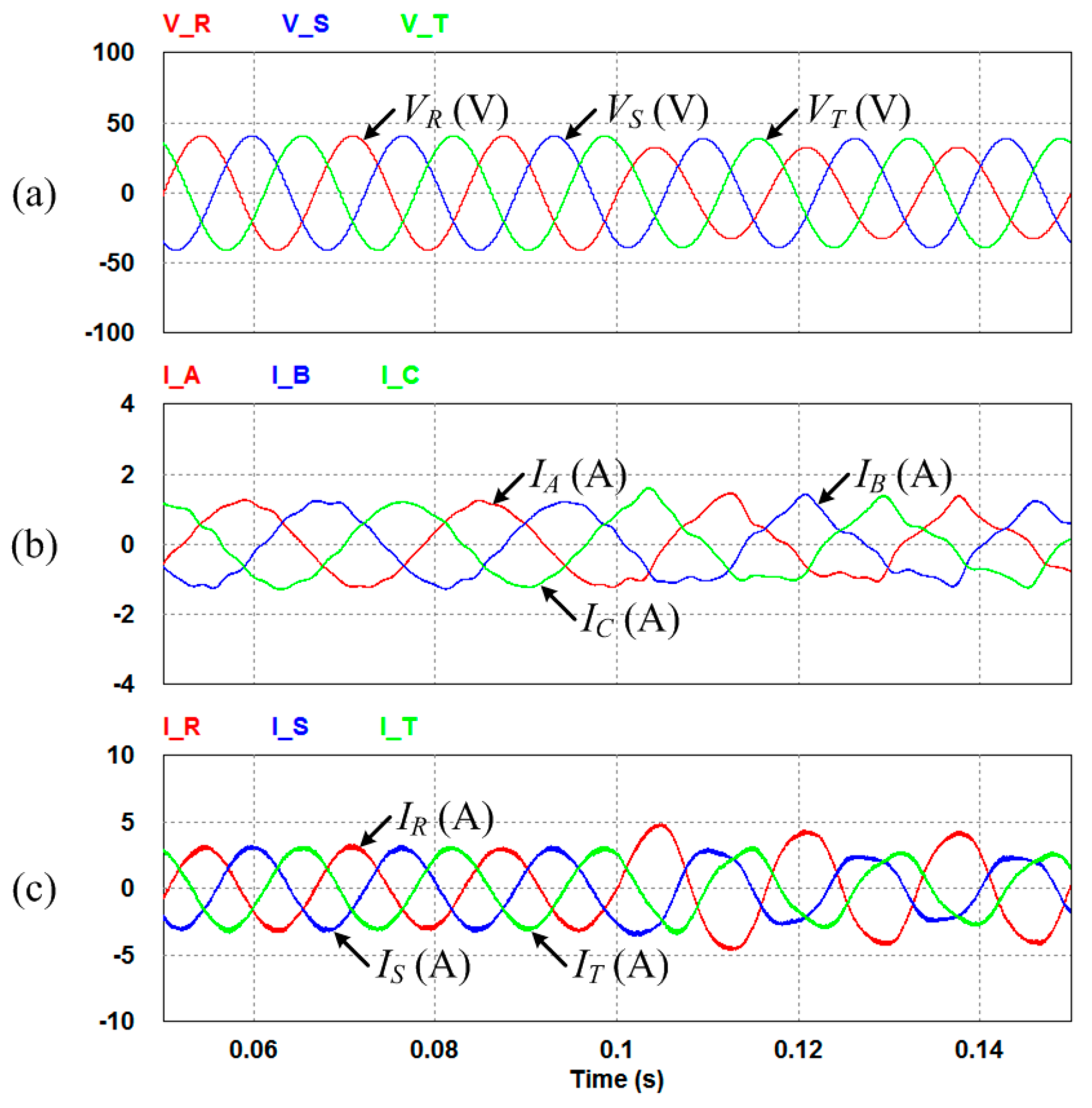
Figure 8 shows simulation results in which the three-phase currents of the CSR and VSI stages are distorted depending on the unbalanced grid voltage conditions. In the same scenario as that of
Figure 6, the PMSG and three-phase grid generate three-phase 37.5-Hz/190-V
peak line-to-line voltages and three-phase 60-Hz/50-V
rms line-to-line voltages, respectively. In addition,
IR,
IS, and
IT are controlled to 3 A using the IMC. However, the three-phase grid is changed to unbalanced voltage conditions at 0.1 s. The
VR is decreased to 70% compared with that of the normal state. Therefore,
IA,
IB, and
IC (as the three-phase currents of the CSR stage) and
IR,
IS, and
IT (as the three-phase currents of the VSI stage) are distorted. As the distorted currents can affect the GS, three-phase grid, and overall system, a control strategy for balancing currents of the CSR and VSI stages is required. In this paper, a control strategy using the positive and negative phase-sequence voltages and currents is proposed for balancing currents of the CSR stage.
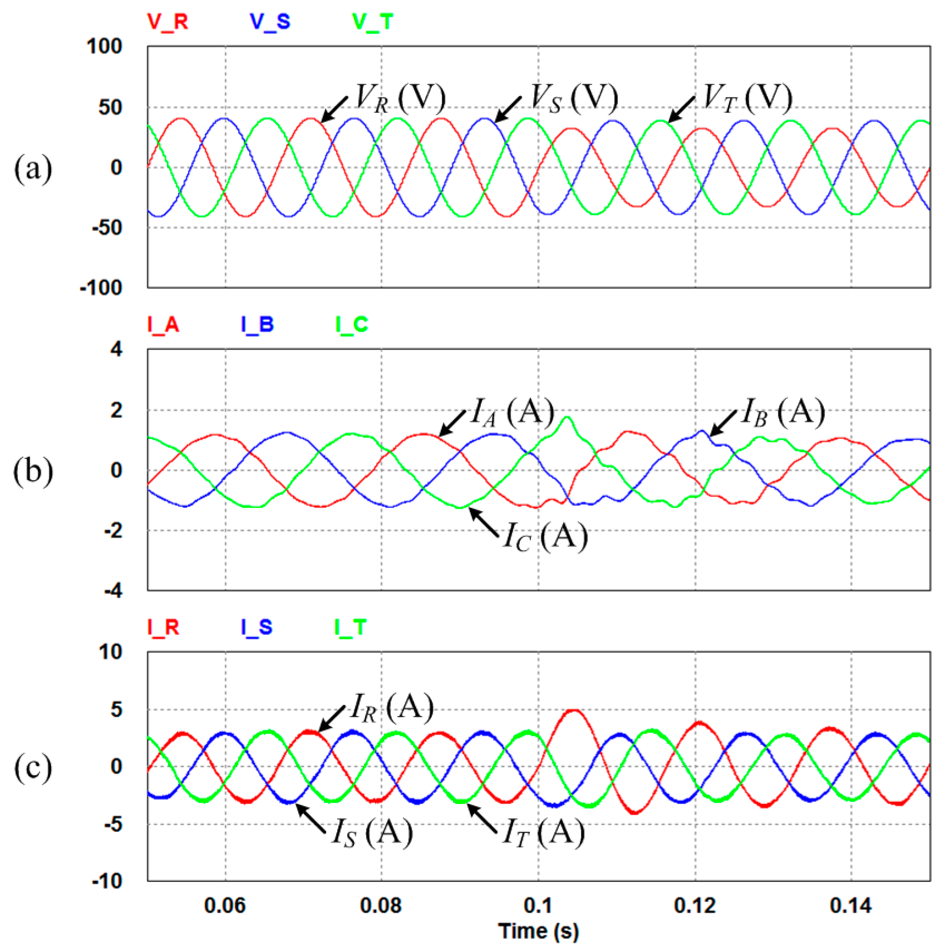
Figure 9 shows simulation results in which the three-phase currents of the CSR stage are controlled to balance currents using the proposed control strategy under unbalanced grid voltage conditions. It has the same scenario as that of
Figure 8. Depending on the proposed control strategy using the new reference currents for the balanced currents of the CSR stage, the distortion of the CSR stage currents decreases. Additionally, the distortion of the VSI stage currents also decreases because the IMC does not have DC-link energy storage elements.
5. Experiment Results
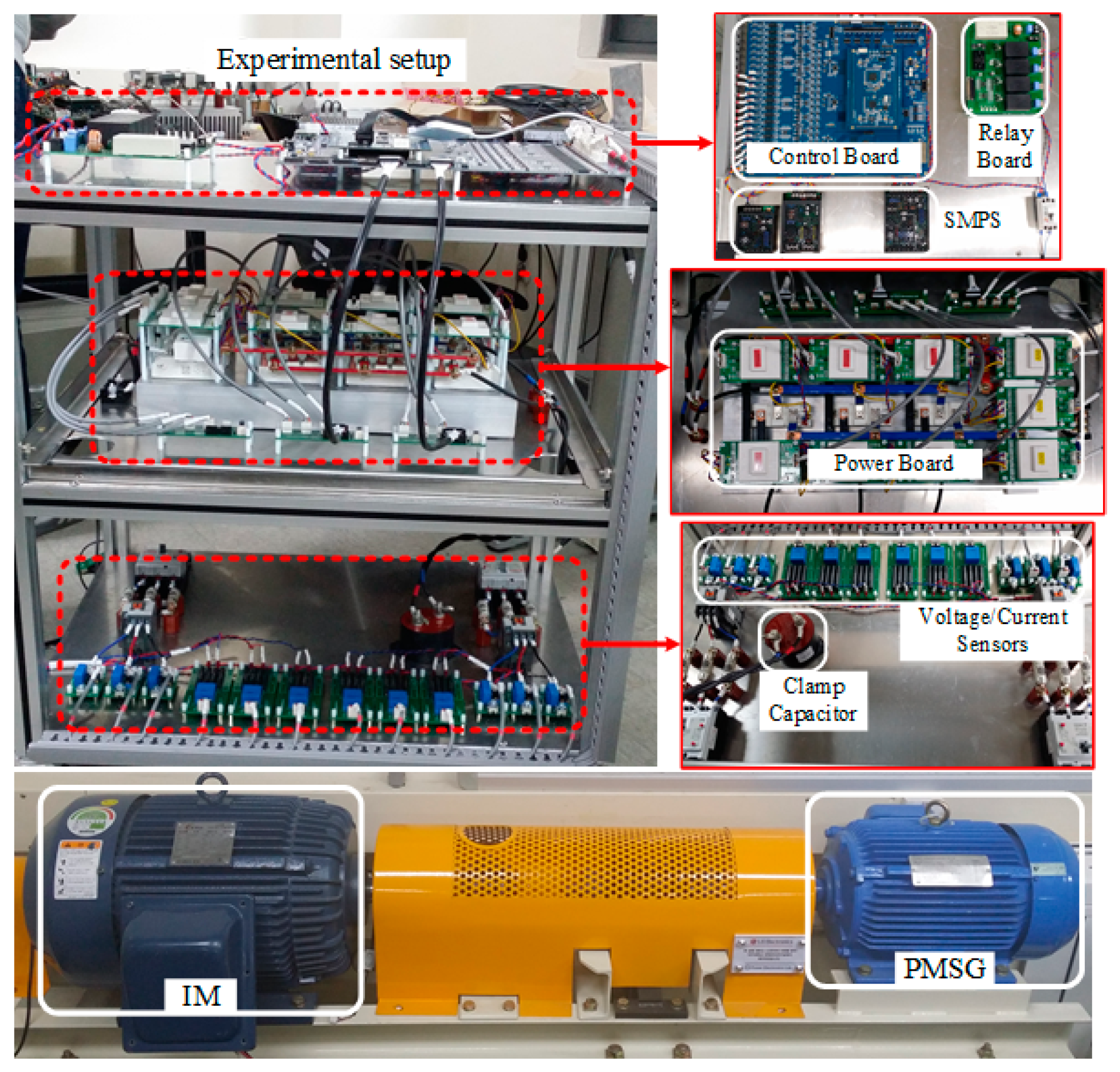
Experiments were performed using the experimental setup shown in
Figure 10 to verify the performance of the proposed control strategy for balanced currents of the CSR stage under unbalanced grid voltage conditions. The experimental setup consists of a control board, power board, and sensors. The control board is composed of a digital signal processor (DSP) using the TMS320C28346 and a field-programmable gate array (FPGA). The power board is composed of a rectifier stage and an inverter stage using the IGBT switches and gate drivers. Additionally, the PMSG of the GS is connected to an induction motor (IM), which is operated by a common inverter to drive at constant speed. The parameters of the PMSG are equal to those of the simulation listed in
Table 2.
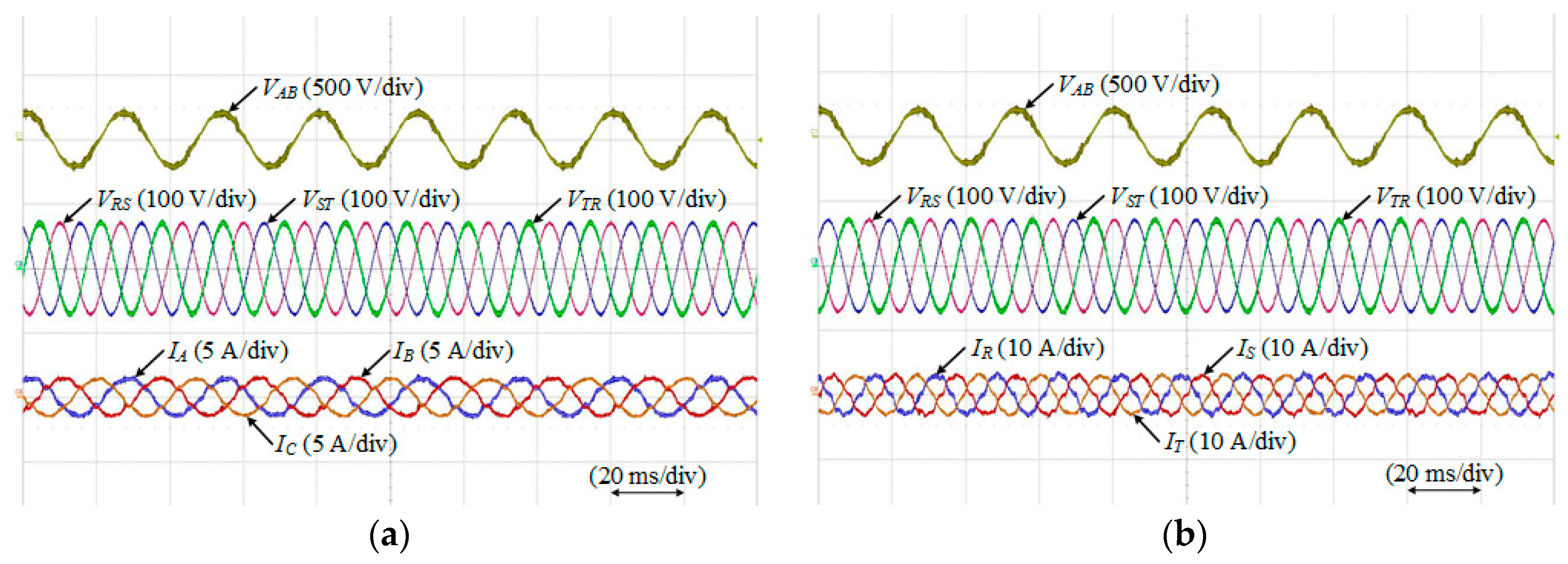
Figure 11a,b shows experimental results where the three-phase currents of the VSI stage are controlled to reference current under balanced grid voltage conditions. It has same scenario as that of
Figure 6. The PMSG of the GS generates three-phase 37.5-Hz/190-V
peak line-to-line voltages such as
VAB. The three-phase grid generates three-phase 60-Hz/50-V
rms line-to-line voltages such as
VRS,
VST, and
VTR. Additionally,
IR,
IS, and
IT (as the three-phase currents of the VSI stage) are controlled to 3 A through the IMC. In this case,
IA,
IB, and
IC (as the three-phase currents of the CSR stage) and
IR,
IS, and
IT are generated to balance currents because the three-phase grid has balanced voltage conditions.
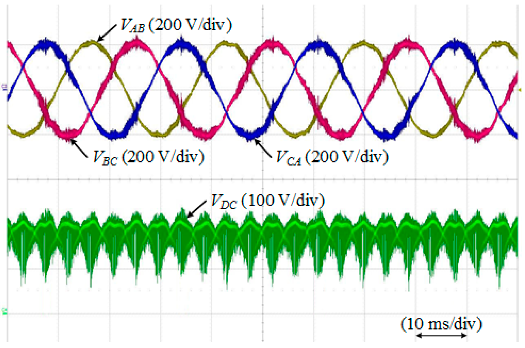
Additionally, experimental results for
VAB,
VBC, and
VCA generated by the PMSG and the
VDC as the fictitious DC-link voltage are shown in
Figure 12. The
VDC of the IMC is generated by the maximum and second-largest magnitudes of
VAB,
VBC, and
VCA.
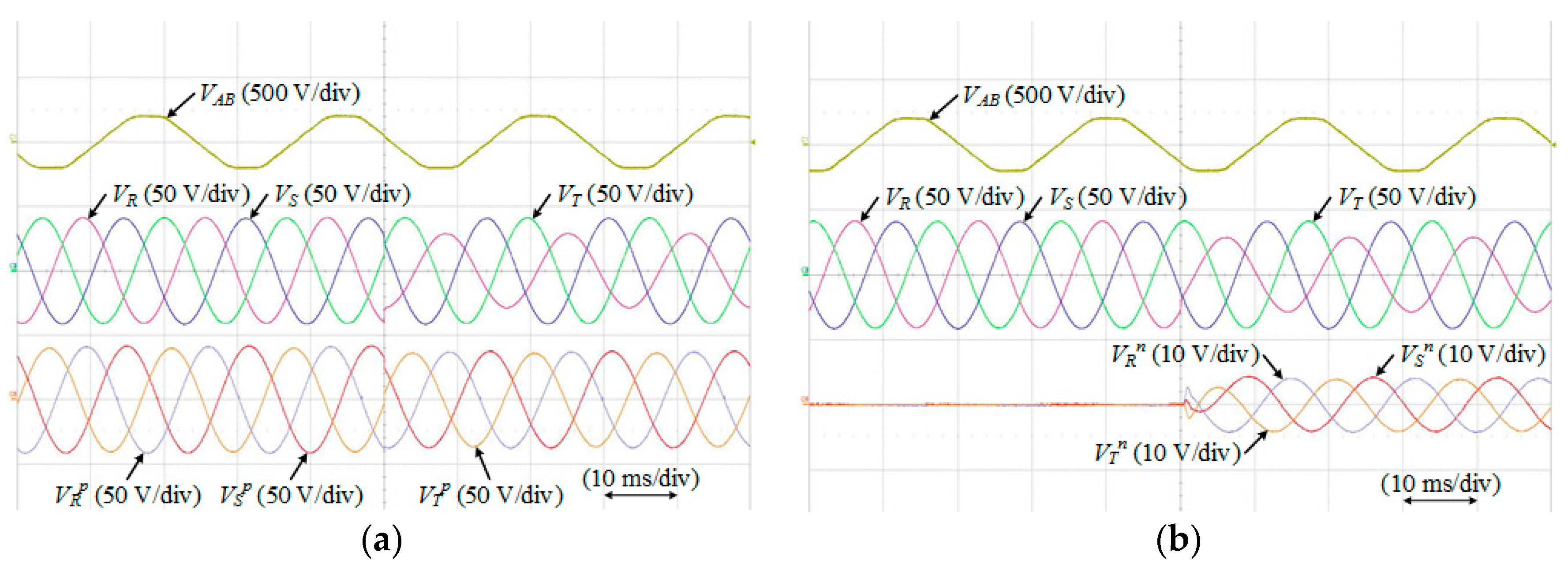
Figure 13a,b shows experimental results where the positive and negative phase-sequence voltages of the VSI stage under unbalanced grid voltage conditions are detected. The three-phase grid is changed to unbalanced voltage conditions from the normal state; in other words, the magnitude of
VR as the
R-phase voltage is decreased to 70% compared with that of the normal state. Depending on the detection method,
,
, and
(as the positive phase-sequence voltages) and
,
, and
(as negative phase-sequence voltages) are detected. They are required to calculate the new reference currents in the proposed control strategy for balanced currents of the CSR stage under unbalanced grid voltage conditions.
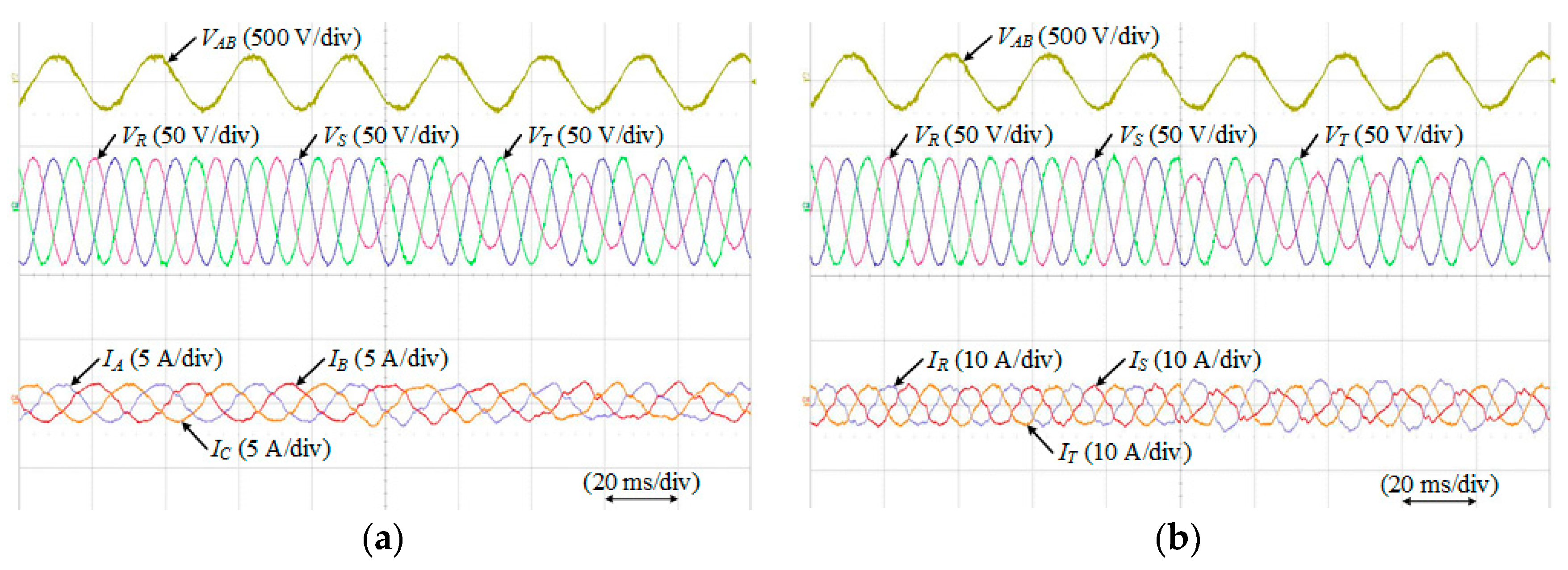
In the same scenario as that of
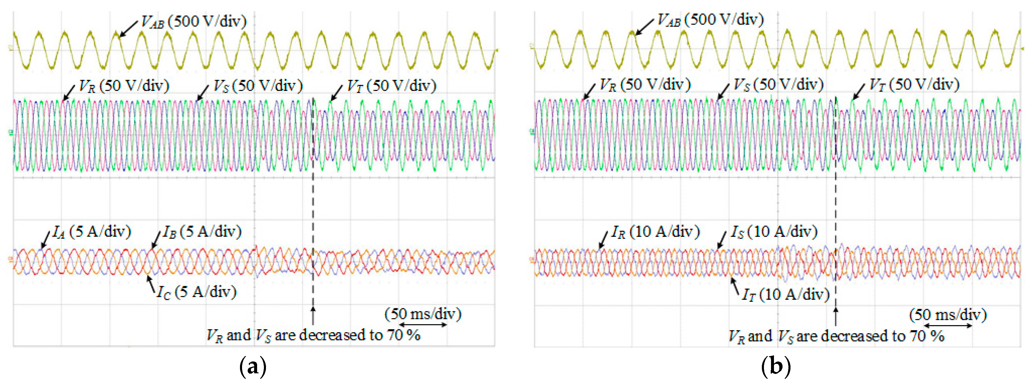
Figure 8, if the three-phase grid has unbalanced voltage conditions, the three-phase currents of the CSR and the VSI stages are distorted. These are shown in
Figure 14a,b, respectively. In this case,
IR,
IS, and
IT are controlled to 3 A using the IMC. However, the three-phase grid is changed to unbalanced voltage conditions where
VR is decreased to 70% compared with that of the normal state. Therefore,
IA,
IB, and
IC (as the three-phase currents of the CSR stage) and
IR,
IS, and
IT (as the three-phase currents of the VSI stage) are distorted. These currents can affect the overall system. Therefore, in this paper, the proposed control strategy with positive and negative phase-sequence voltages and currents is used to balance currents of the CSR stage.
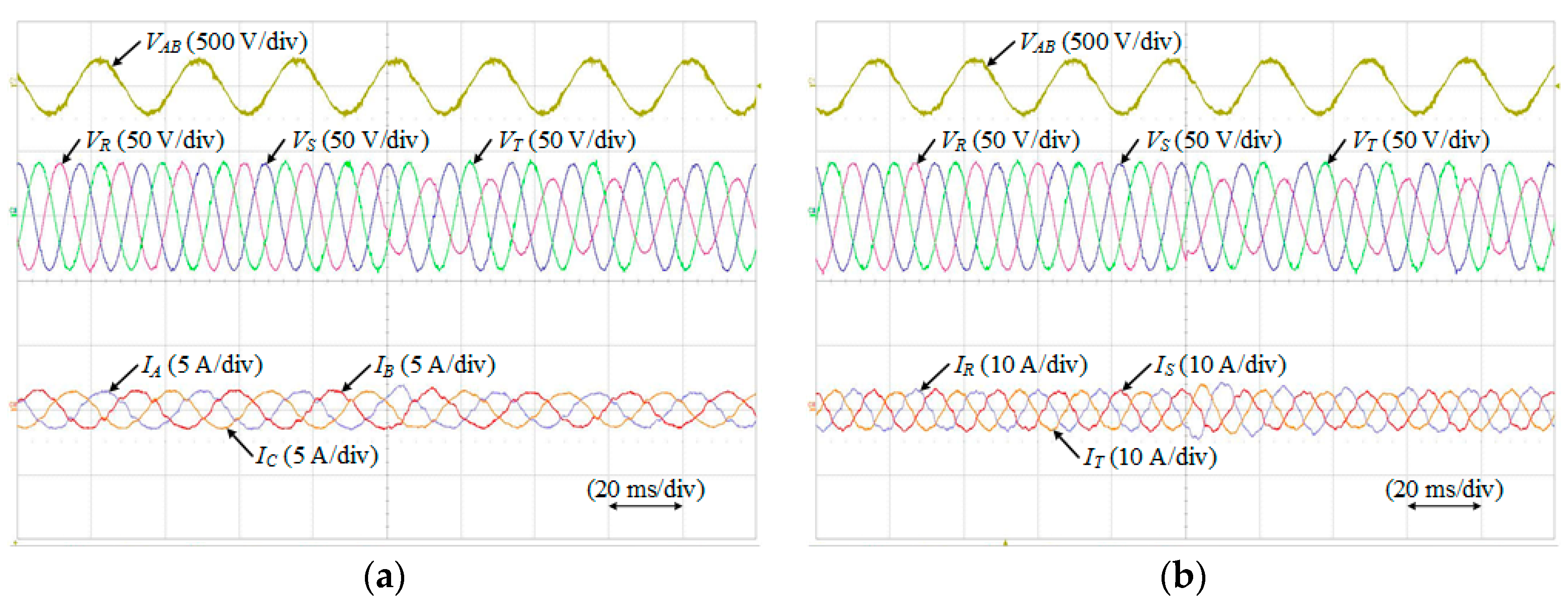
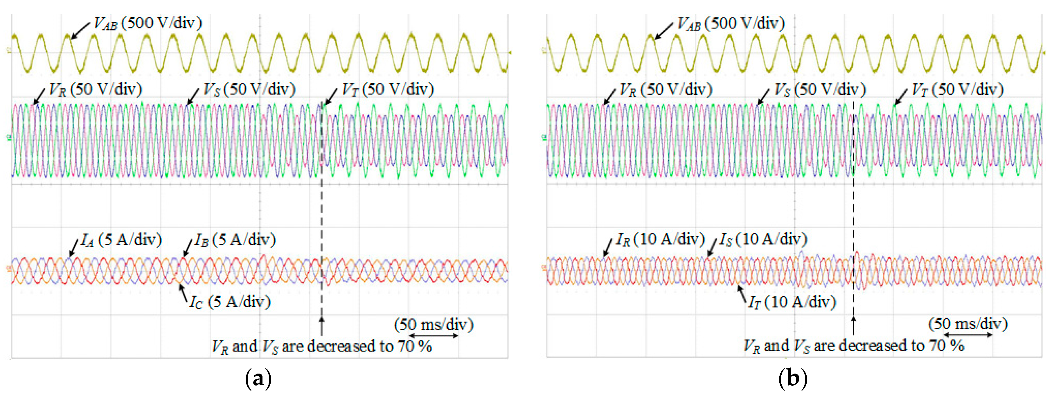
Figure 15a,b shows experimental results where the three-phase currents of the CSR stage are controlled to balance currents using the proposed control strategy under unbalanced grid voltage conditions. Although the three-phase grid has unbalanced voltage conditions,
IA,
IB, and
IC (as the three-phase currents of the CSR stage) and
IR,
IS, and
IT (as the three-phase currents of the VSI stage) are controlled to balance currents depending on the proposed control strategy. The distortion of the CSR stage and the VSI stage currents decreases compared with that of
Figure 14.
In addition,
Figure 16a,b shows experimental results where the three-phase currents of the CSR and the VSI stages are distorted under unbalanced grid voltage conditions. In this case,
IR,
IS, and
IT are controlled to 3 A using the IMC. However, the three-phase grid is changed to unbalanced voltage conditions where
VR and
VS are decreased to 70% compared with those of the normal state. Therefore, the three-phase currents of the CSR and the VSI stages are distorted.
In the same scenario as that of
Figure 16a,b,
Figure 17a,b shows experimental results where the three-phase currents of the CSR stage are controlled to balance currents using the proposed control strategy under unbalanced grid voltage conditions depending on decreases in two-phase grid voltages. Although the three-phase grid has unbalanced voltage conditions,
IA,
IB, and
IC (as the three-phase currents of the CSR stage) and
IR,
IS, and
IT (as the three-phase currents of the VSI stage) are controlled to balance currents using the proposed control strategy.
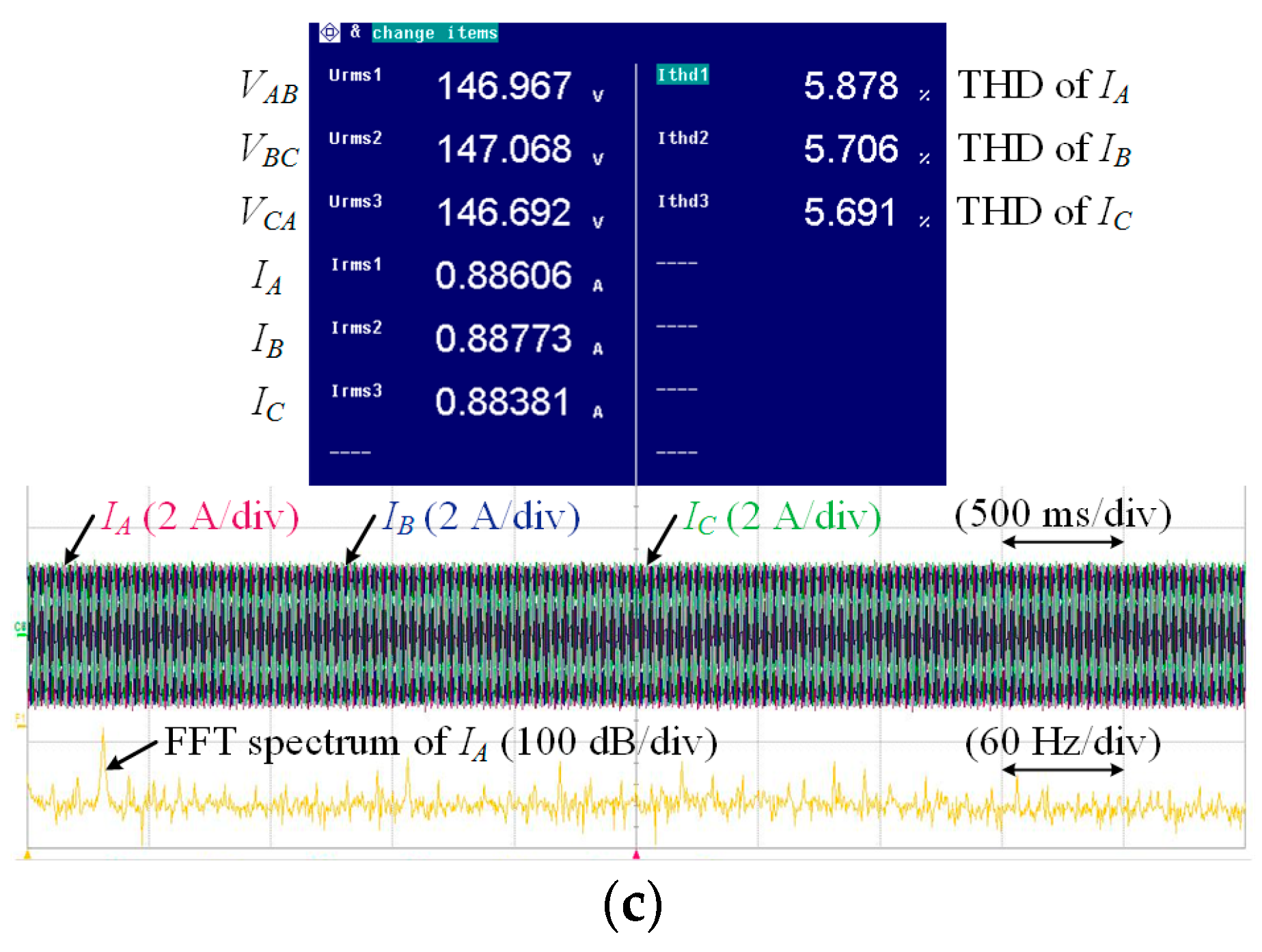
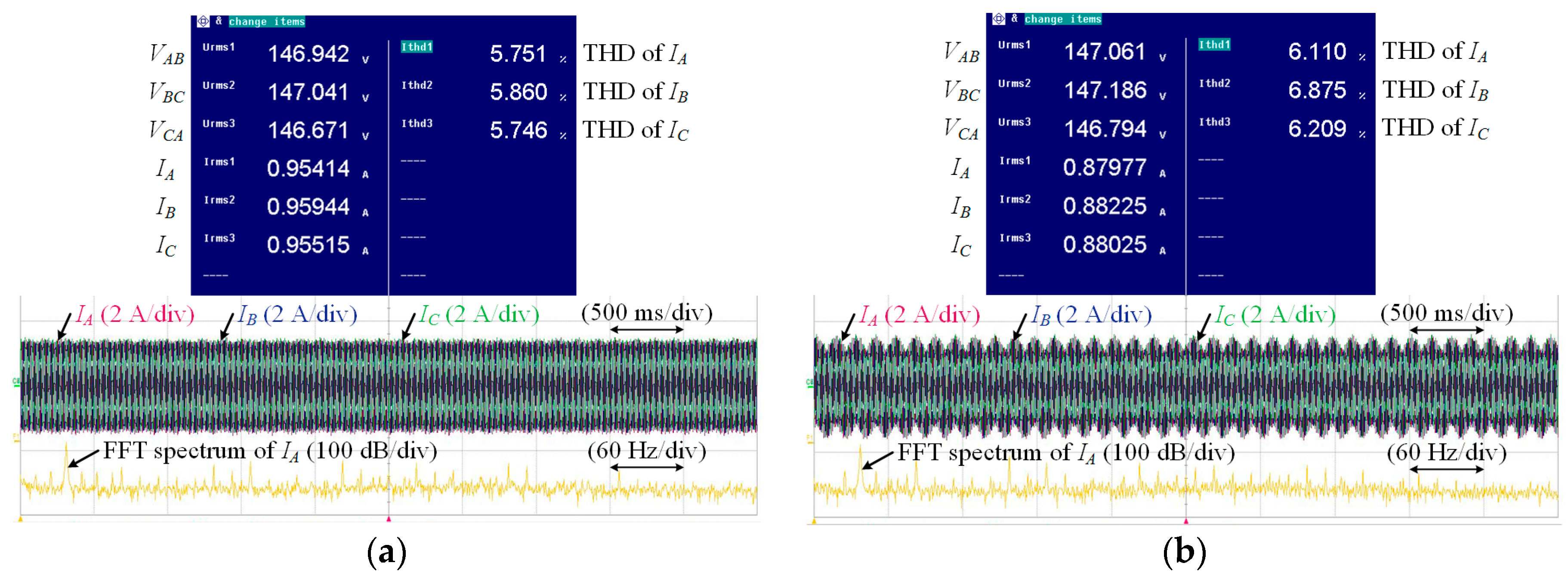
Additionally, total harmonic distortion (THD) analysis for the three-phase currents of the CSR and VSI stage are progressed depending on the grid voltage condition and the control strategy.
Figure 18a–c shows experimental results of THD analysis for the three-phase currents of the CSR stage such as
IA,
IB, and
IC and fast Fourier transform (FFT) spectrum of
IA. They have same scenario as that of
Figure 11a,
Figure 14a, and
Figure 15a, respectively. In
Figure 18a, the three-phase grid has balanced voltage conditions and the three-phase current of the VSI stage are controlled to reference current using the general control strategy. However, in
Figure 18b,c, the three-phase grid has unbalanced voltage conditions depending on decreasing of the magnitude of
VR compared with that of the normal state. Therefore,
IA,
IB, and
IC are distorted and THDs of them are increased as shown in
Figure 18b. In
Figure 18c, the three-phase currents of the VSI stage are controlled using the proposed control strategy for the balanced currents of the CSR stage. As a result, THDs of
IA,
IB, and
IC are decreased.
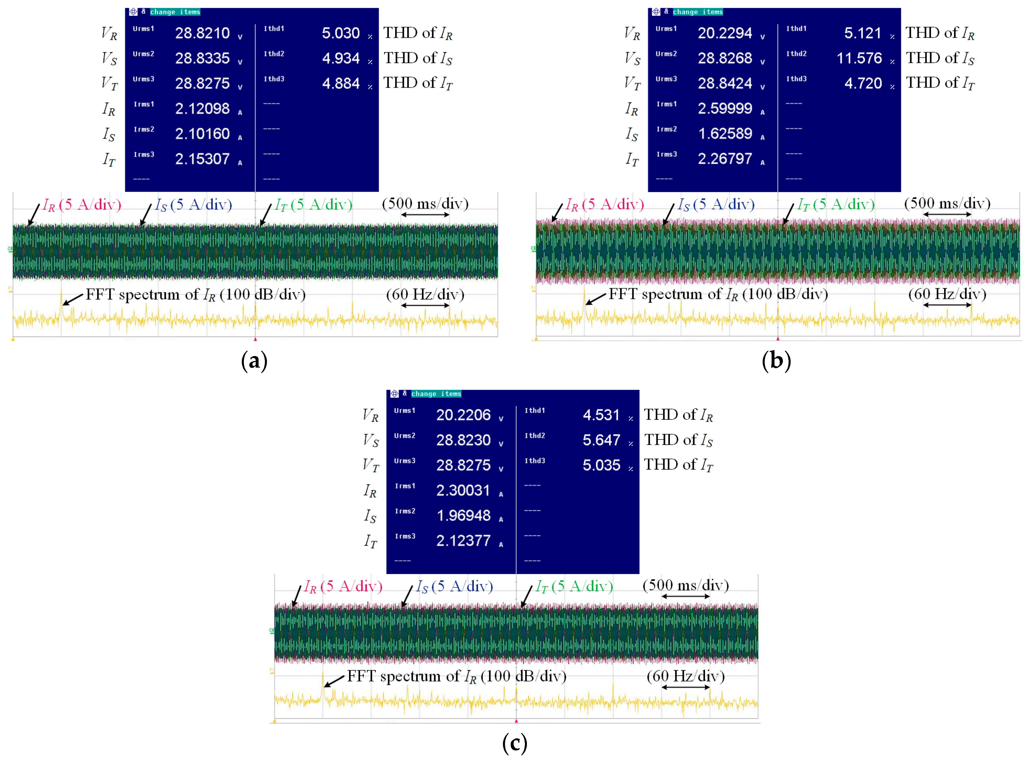
Figure 19a–c shows experimental results of THD analysis for the three-phase currents of the VSI stage such as
IR,
IS, and
IT and FFT spectrum of
IR. They have same scenario as that of
Figure 11b,
Figure 14b and
Figure 15b, respectively. In
Figure 19a, the three-phase grid such as
VR,
VS, and
VT has balanced voltage conditions. Therefore,
IR,
IS, and
IT are controlled to reference current using the general control strategy as balanced currents. However, in
Figure 19b,c, the magnitude of
VR decreases to 70% compared with that of the normal state. Therefore,
IR,
IS, and
IT are distorted under unbalanced grid voltage conditions. Above all,
IS as
S-phase current of the VSI stage is heavily distorted as shown in
Figure 14b. Therefore, THD of
IS is increased as shown in
Figure 19b. In
Figure 19c, the three-phase currents of the VSI stage are controlled using the proposed control strategy for the balanced currents. As a result, THDs of
IR,
IS, and
IT are decreased.


