Article

Multi-Agent System Fault Protection with Topology Identification in Microgrids

1
Department of Electrical Engineering, National Taiwan University of Science and Technology, No. 43, Sec. 4, Keelung Rd., Da’an District, Taipei 10607, Taiwan
2
Department of Electrical Engineering, St. John’s University, No. 499, Sec. 4, Tam King Rd., Tamsui District, New Taipei City 25135, Taiwan
3
Institute of Nuclear Energy Research, No. 1000, Wenhua Rd. Jiaan Village, Longtan District, Taoyuan 32546, Taiwan
*
Author to whom correspondence should be addressed.
Energies 2017, 10(1), 28; https://doi.org/10.3390/en10010028
Submission received: 11 October 2016 / Revised: 15 December 2016 / Accepted: 20 December 2016 / Published: 27 December 2016
(This article belongs to the Special Issue Smart Microgrids: Developing the Intelligent Power Grid of Tomorrow)

Abstract

:
Data acquisition and supervisory control are usually performed using client-server architecture and centralized control in conventional power systems. However, the message transmission and fault clearing are too slow for large-scale complex power systems. Microgrid systems have various types of distributed energy resources (DERs) which are quite different in characteristics and capacities, thus, the client-server architecture and centralized control are inadequate to control and operate in microgrids. Based on MATLAB/Simulink (ver.R2012a) simulation software and Java Agent Development Framework (JADE) (JADE 4.1.1-revision 6532), this paper proposes a novel fault protection technology that used multi-agent system (MAS) to perform fault detection, fault isolation and service restoration in microgrids. A new topology identification method using the YBus Matrix Algorithm is presented to successfully recognize the network configurations. The identification technology can respond to microgrid variations. Furthermore, the interactive communications among intelligent electronic devices (IEDs), circuit breakers (CBs), and agents are clarified during fault occurrence. The simulation results show that the proposed MAS-based microgrids can promptly isolate faults and protect the system against faults in real time.

1. Introduction

This work builds on a recent conference paper [1] concerning fault protection coordination in microgrids. Compared with the conference paper, a new topology identification method and some performed study cases are presented in this paper. There are many sources of energy that harness natural processes and thus considered renewable and environmentally friendly. Renewable energies are under active development in many countries. Facing the global energy crisis, microgrid systems are effective approaches to solve the energy issue and reduce carbon dioxide emissions [2,3,4]. Centralized control is adopted in conventional large-scale and high-voltage power systems. In contrast, a microgrid system usually consists of small-scale and low-voltage distributed energy resources (DERs) like photovoltaics (PVs), fuel cells, wind power, and micro-turbines. The characteristics and capacities of DERs are quite different [5,6]. As a result, the conventional centralized control is inadequate for microgrid systems [7,8,9]. To solve this problem, a novel multi-agent system (MAS) based on topology identification method is proposed in this paper.
An agent can be viewed as a system that is able to perceive its environment through sensors and act upon that environment through actuators, so it can be said that a MAS is a computer-based system, which comprises multiple intelligent agents that are able to interact with each other and carry out their tasks independently without having to wait for a central control signal. The individual agents can cooperate with other agents to achieve individual objectives, or coordinate to achieve global objectives. Furthermore, a MAS with highly autonomy and flexibility can make a decision based on its own judgment to fulfill a specified task or partition a complicated task into several smaller and simpler ones, each to be tackled by an individual agent. Many studies have been reported on the application of MASs to microgrids [10,11,12,13,14,15,16,17,18].
A network topology processor (NTP) utilizes the recent circuit breaker (CB) status to determine the topology of an electrical distribution network. Extensive research has been conducted on topology identification methods [19,20,21,22,23,24,25]. In this paper, a new Topology Identification Matrix method applied in a multi-agent-based microgrid system is proposed to perform MAS protection coordination. The CB status in the microgrids was gathered and converted into a so-called YBus matrix to evaluate the faults. This work reveals how to determine the required settings of CB agents for the fault protection coordination both in grid-connected and islanded modes. The main contributions of the current paper are that a new Topology Identification Matrix method was developed for a microgrid system with a dynamic network and a MAS protection coordination strategy was used for fault protection. The proposed approach is verified for the case of symmetrical faults of a radial distribution system.

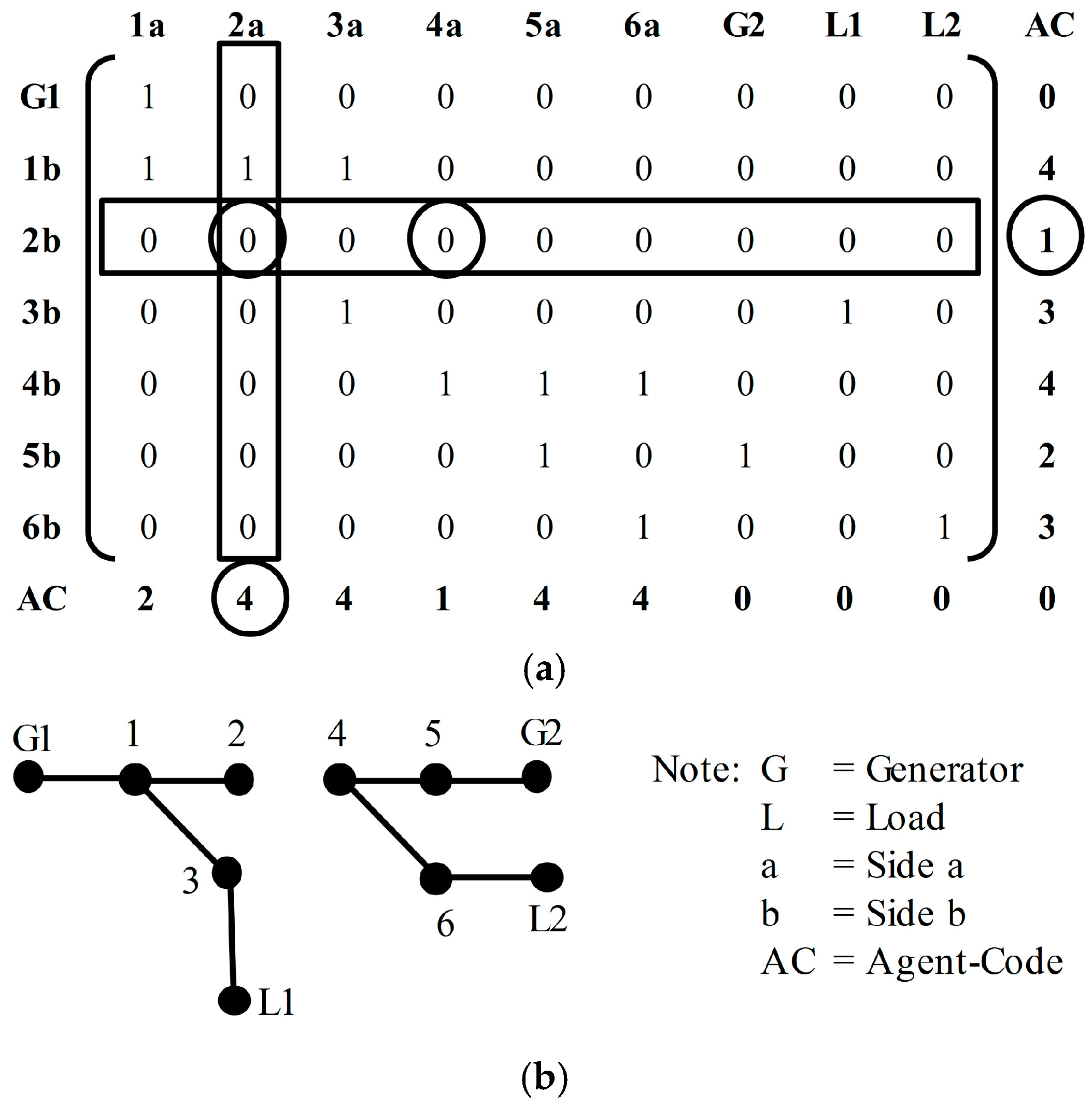
2. Topology Identification Matrix Method

In this paper, a new method for the determination of electrical distribution network topology based on the YBus Matrix Algorithm has been developed. The proposed approach is mainly divided into two parts. The first part records and models CB status, and then forms a matrix called a Topology Matrix (TM). The TM is used to describe all the connection information of a microgrid. The second part constructs the YBus matrix that is used for fault analysis and finding the setting parameters of relays. In this work, the approach is applied to a radial distribution system with DER penetration.

2.1. Topology Matrix Model

The topology of an electrical distribution network can be determined by the CB status obtained from CB agents. CBs and CB agents are placed on both sides of distribution lines, and terminal sides of generators and loads. The agents on the distribution lines, generator, and load are called Lines Agent, Generator Agent, and Load Agent, respectively. In addition, all the microgrid connections are recorded in the TM.
To develop the TM model, the agent code (AC) is established in Table 1 according to the node connection type. Figure 1a shows an example network in which the CB is simply modeled by a sequence of numbers 1, 2, …, 6. The two sides of CB are labeled as “a” and “b” as shown in Figure 1b. In Figure 1c, each side “a” and “b” is respectively registered on the column header and row header of the TM. In the TM, the CB status is placed in the corresponding matrix element position. CB ON and OFF are represented as 1 and 0, respectively. Furthermore, the connections of CB terminals between components (CB, generator or load) are done in the same way. The connected and not-connected components are labeled as 1 and 0, respectively. Finally, every terminal number (both rows and columns) is completed with the AC listed in Table 1 that gives the information about what kind of agent or node is connected to the next components. For example, the terminal 1b connects with 1a through CB1, and connects with 2a and 3a through Bus B1 (AC = 4). This case is listed in the second row of TM. The simplified topology graph for the TM model is shown in Figure 1d.
The key feature of the TM is that it reveals all the connection information in the electrical network system. In other words, the CB status can be identified by the TM model. If one of the CBs trips, the entire row or column of TM associated with the trip CB will be updated and zeroed for comparison between with AC. This can be formulated as:
TM(all.row, TCB) = 0 if ACTCB.a < ACTCB.b
TM(TCB, all.col) = 0 if ACTCB.a > ACTCB.b
where TCB is the Tripped-CB and TCB.a and TCB.b are the terminal sides of Tripped-CB. For example, if CB2 trips, the entire row 2b is set to zero because ACTCB.2a (=4) > ACTCB.2b (=1). The resulting TM can be updated as shown in Figure 2a. Accordingly, the corresponding topology graph is shown in Figure 2b.

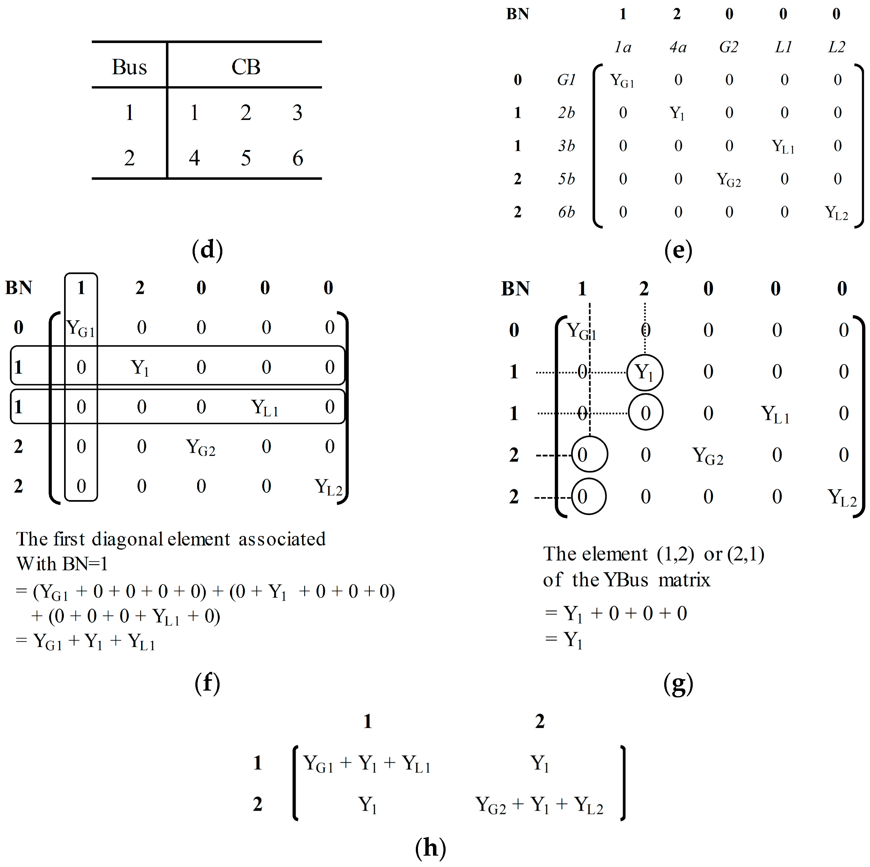
2.2. YBus Matrix Algorithm

As mentioned above, in the electrical distribution network, the connection between CBs and components can be identified from the TM model. However, the TM model cannot be used for fault analysis. To perform fault analysis in microgrids, the TM model requires conversion to a so-called YBus Matrix. The TM model obtained from Figure 1a–c is shown in Figure 3a and it is used to perform the conversion. The conversion process is illustrated as follows:

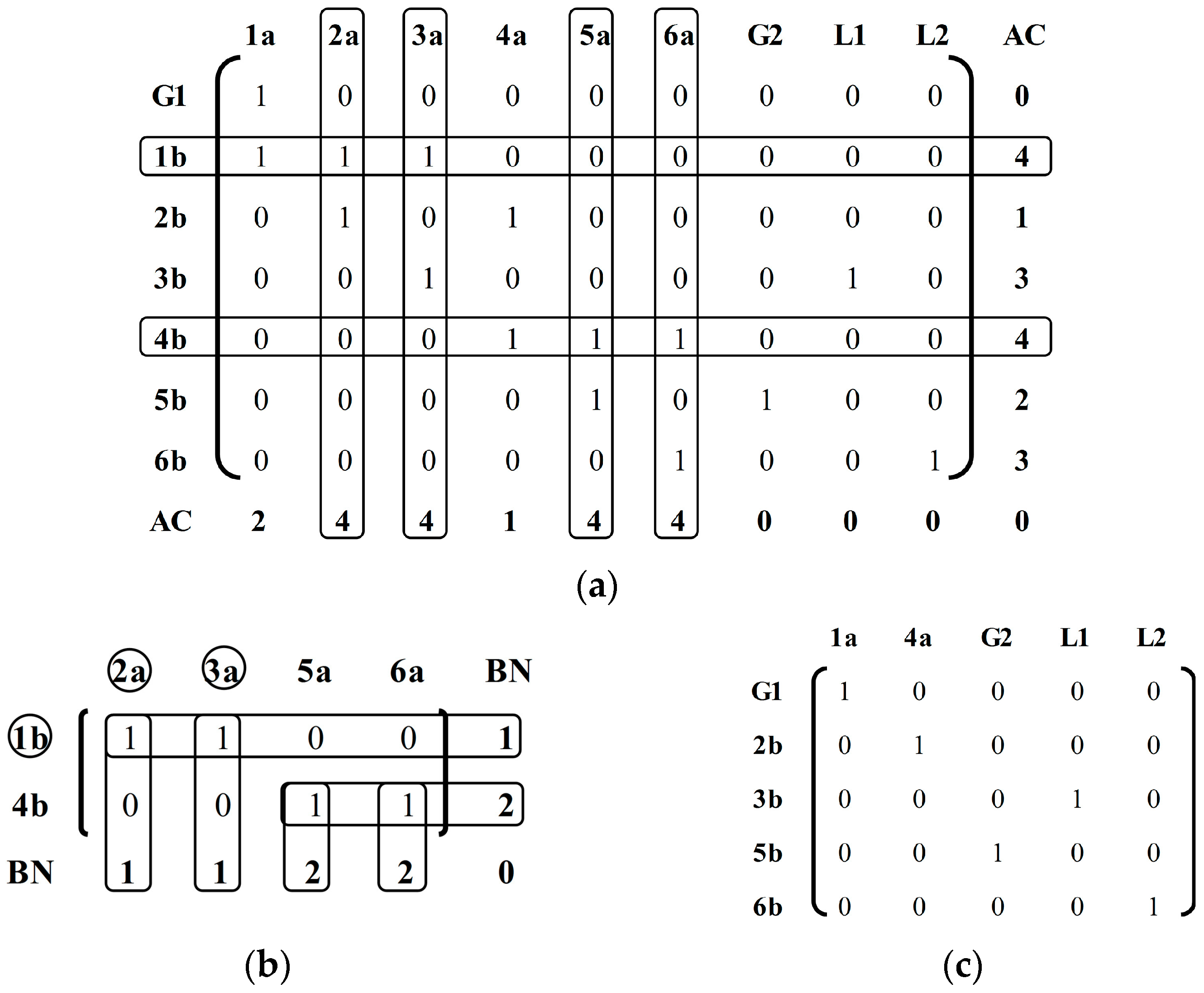
2.2.1. Step 1: Extract the Conversion Matrix (CM) and Base Matrix (BM) from the Topology Matrix (TM)

First, choose the rows and columns of TM associated with all ACs (agent codes) = 4 to construct the CM that describes the bus connection information in the network. The constructed CM is obtained and shown in Figure 3b, where BN is the bus number. After subtracting rows and columns associated with all AC = 4, the rest of TM is then BM and given in Figure 3c.

2.2.2. Step 2: Construct the Conversion Table from CM and the Modified BM

It can be seen that there are two rows in CM, and then the network has two buses. The CM gives all the bus connection information. From the example system in Figure 1a, CBs 1, 2, and 3 are connected to bus 1 and CBs 4, 5, and 6 are connected to bus 2. The connection information is tabulated in Figure 3d that is referred to as the conversion table. Next, BM in Figure 3c needs to be modified. Based on the conversion table, the terminal sides of CBs in BM are replaced by the connected-bus number. The modified BM is given in Figure 3e. From the comparison of Figure 3c,e it can be seen that CBs 1a, 2b, and 3b are replaced by BN = 1 and CBs 4a, 5b, and 6b are replaced by BN = 2. In addition, all the elements 1 in BM are replaced by their corresponding network admittances.

2.2.3. Step 3: Complete the YBus matrix

Finally, the YBus matrix will be found by performing the modified BM. The YBus matrix is a symmetric matrix in which the first and second diagonal elements are computed by adding all the rows and columns of the modified BM associated with BN = 1 and 2, respectively. Figure 3f illustrates the finding of the first diagonal element. The remaining elements of the YBus matrix are obtained by adding the elements of BM that are rows corresponding to BN = i and all columns corresponding to BN = j, where ij ≠ 0. The case is illustrated in Figure 3g, and then the resulting YBus matrix is given in Figure 3h.

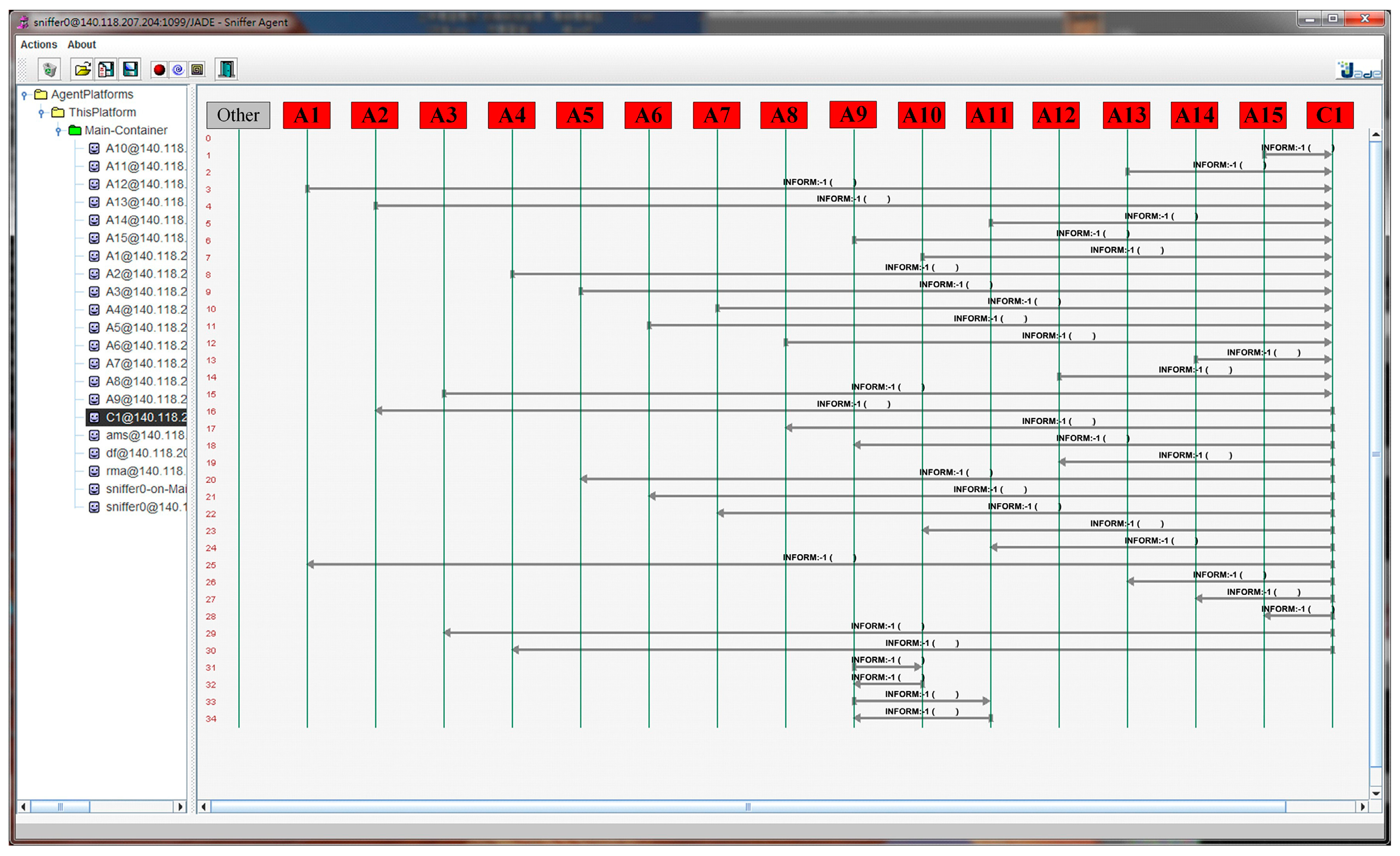
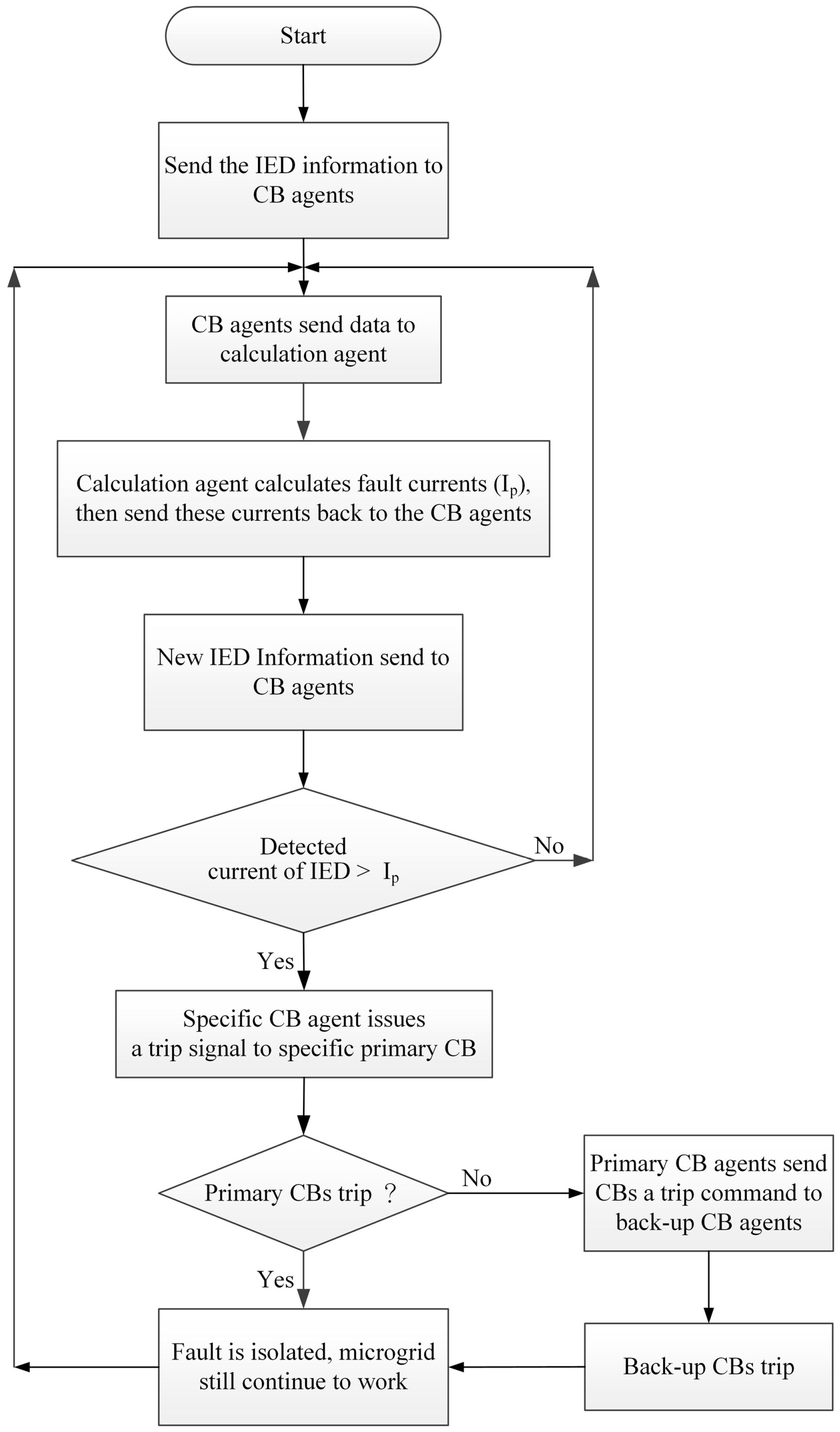
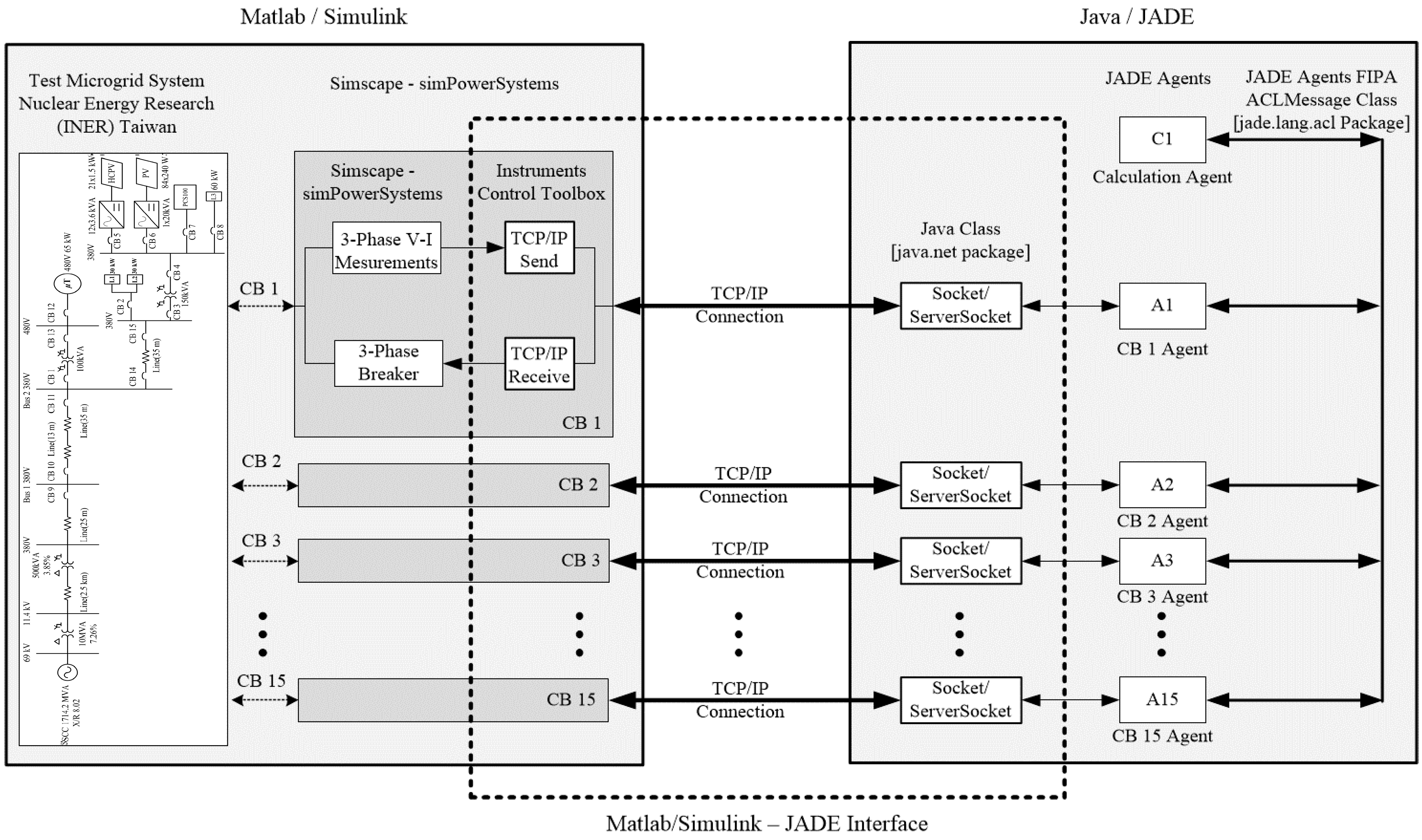
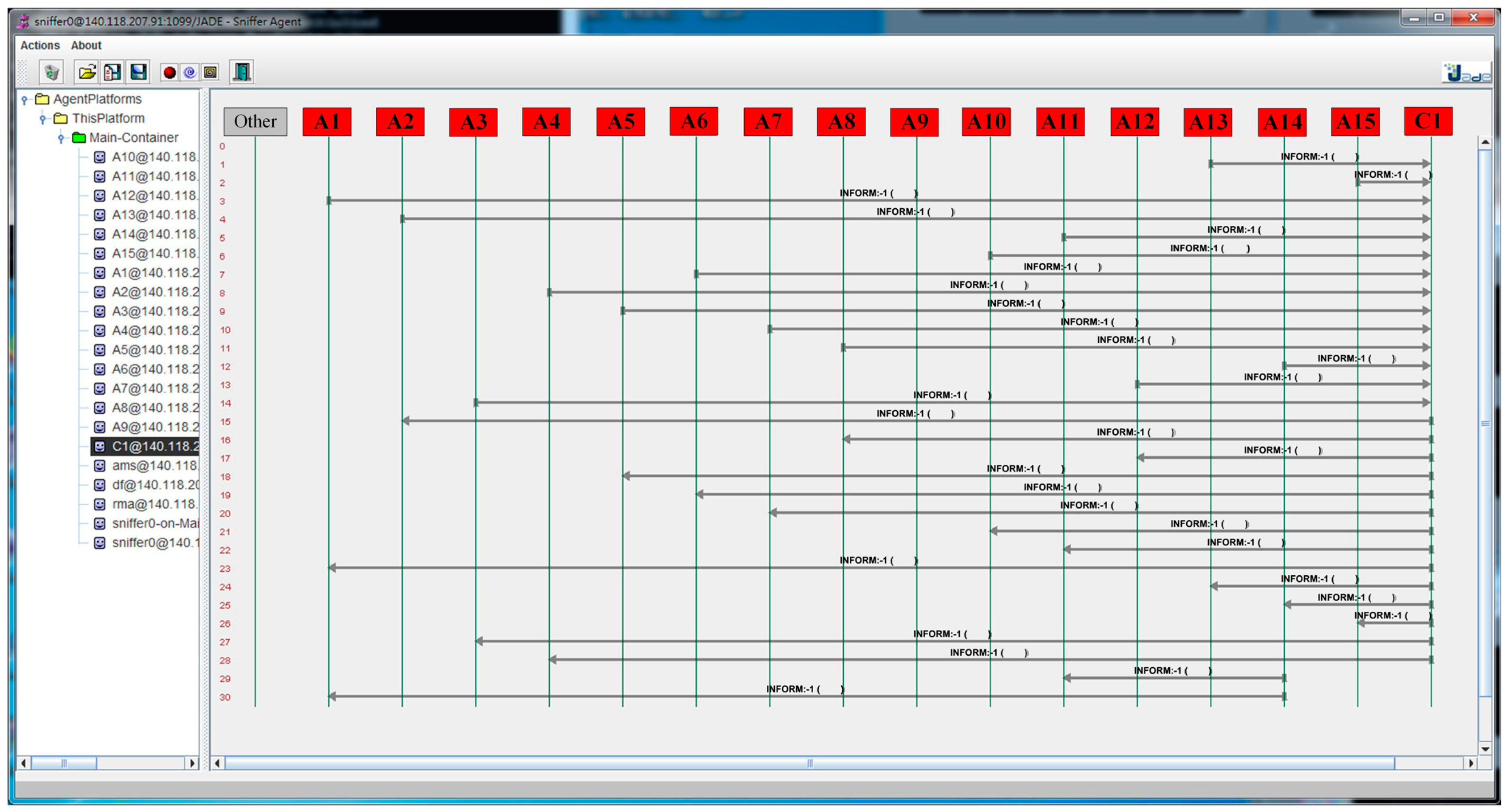
3. Multi-Agent System for Microgrid Protection Coordination

An IED in the multi-agent microgrid system can access the CBs information such as line voltage, line current and CLOSE/TRIP status of CB, and transmit them to the corresponding CB agent. Receiving the information, the calculation agent calculates the three-phase short circuit fault current of near-end by using the topology identification method and the YBus Matrix Algorithm. The detailed operations of MAS applied in fault protection of microgrids are illustrated in the flowchart shown in Figure 4.
The calculated current (i.e., IED’s pick-up current, Ip) is sent back to CB agent and compared with the line current detected by the IED that determines whether the CB needs to be tripped. If the line current is larger than Ip, the CB agent will issue a trip command to a specific CB and isolate the fault. Moreover, once the main protection CB fails to trip, the CB agent will communicate with others and issue a specific trip command to back-up the CB protection to minimize the affected area and promptly protect the microgrid. The protection mechanism insures that the parts of the microgrid can normally operate in islanded mode, that is, generators can still continue to supply electric power, and important loads can still work. Specifically, the multi-agent technology can be used for fault detection, fault isolation and service restoration in electrical distribution networks. Undeniably, MAS could provide an alternative to a centralized processing system. In this study, MATLAB/Simulink simulation software is used to establish a MAS-based microgrid. Java Agent Development Framework (JADE) is an open source agent development software framework for building Foundation for Intelligent Physical Agents (FIPA)-compliant MASs. The studied test microgrid system in this work was simulated in Matlab/Simulink (ver.R2012a) using Simscape—simPowerSystems component libraries. The agents of the MAS were also simulated in JADE. The interface of the Matlab/Simulink model and JADE is TCP/IP communication protocol. Additionally, the TCP/IP Send block and Receive block in the Instruments Control Toolbox of Simulink are used as data sender and receiver in the power system model side. The entire system interface between Matlab/Simulink and JADE is shown in Figure 5.

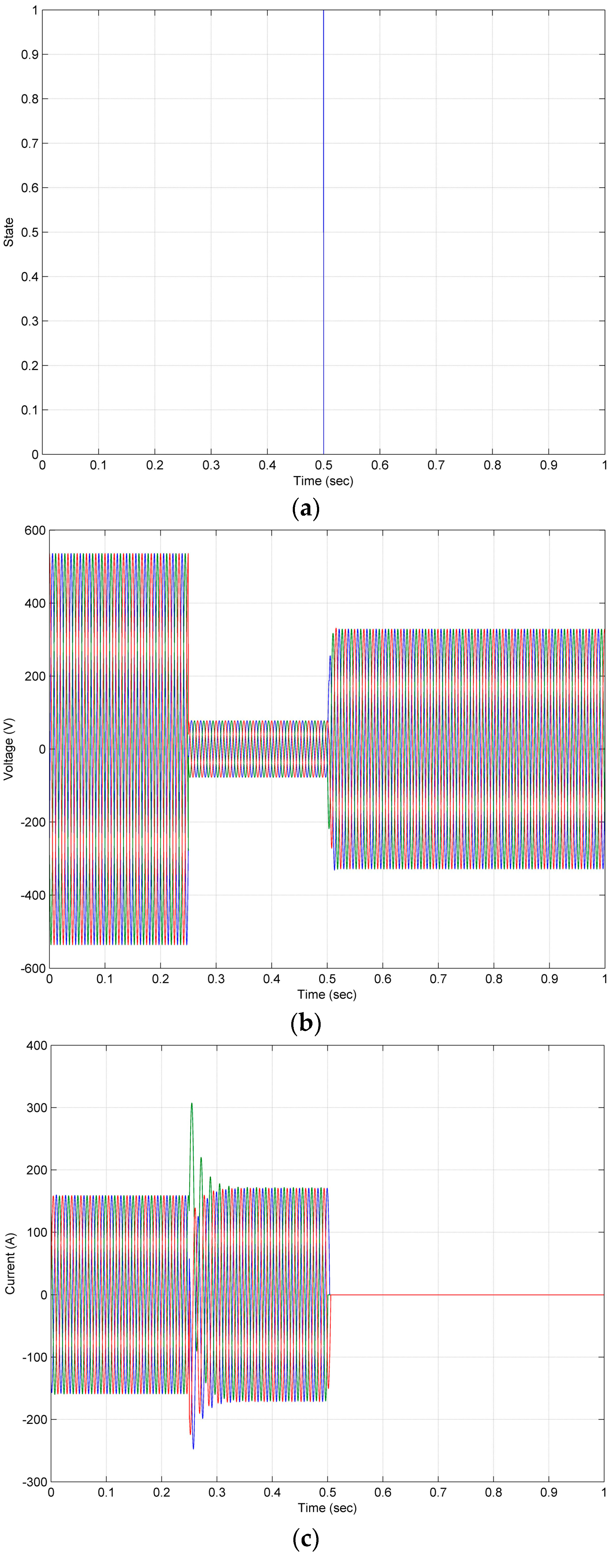
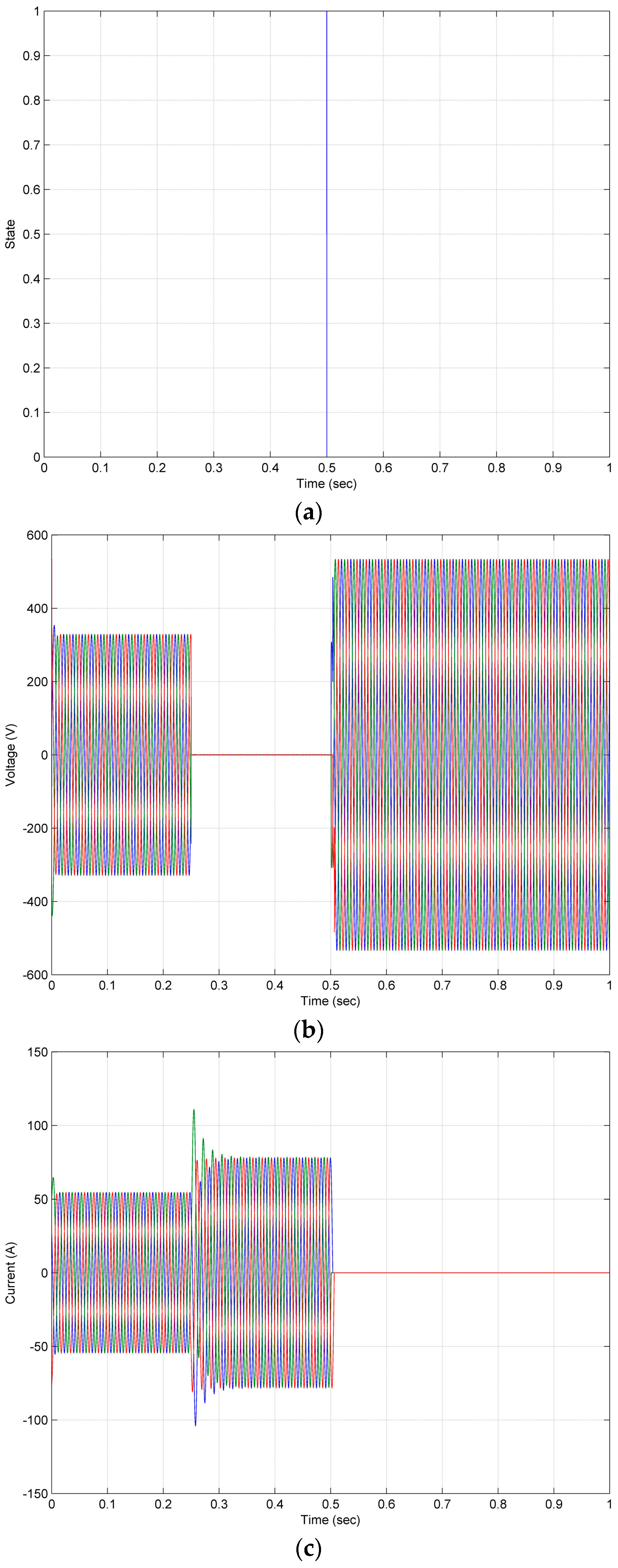
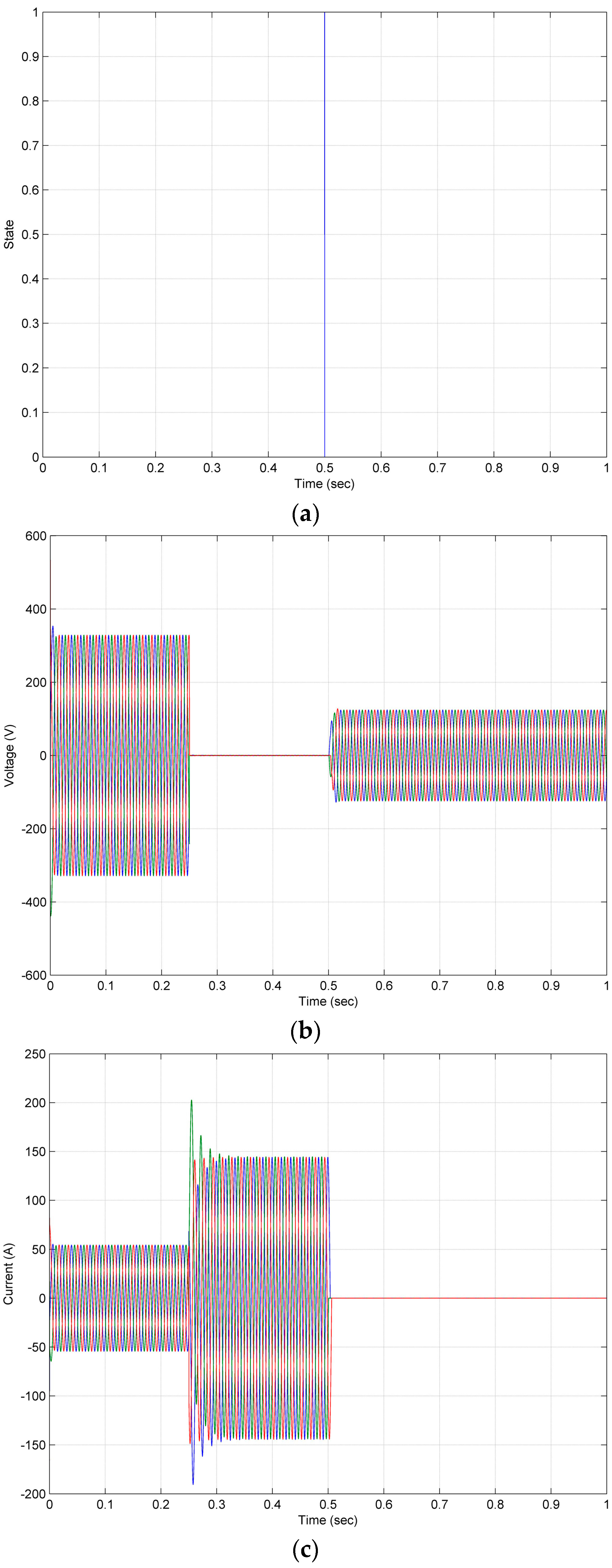
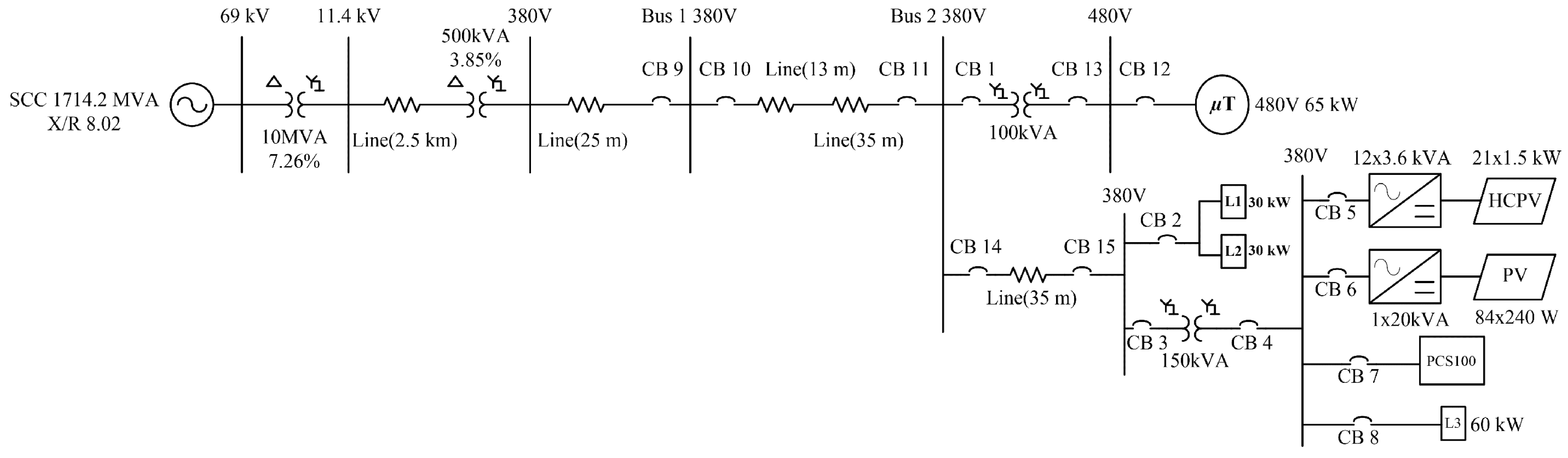
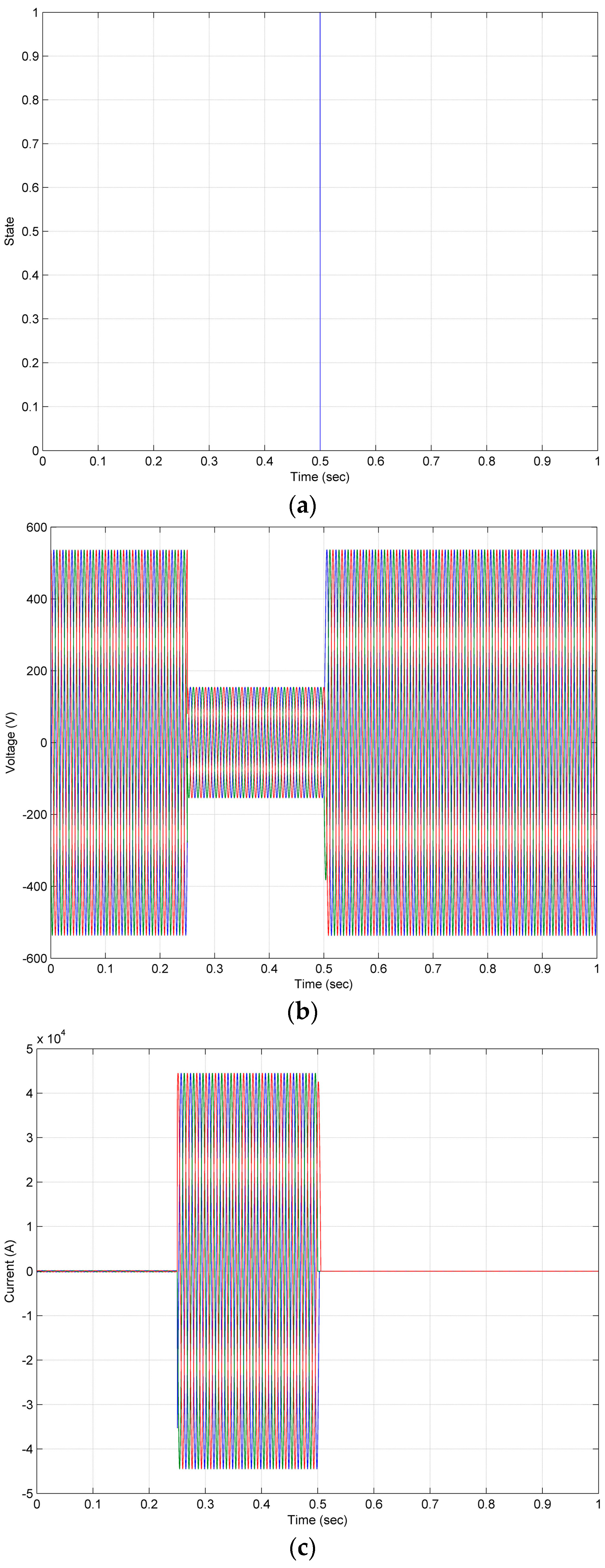
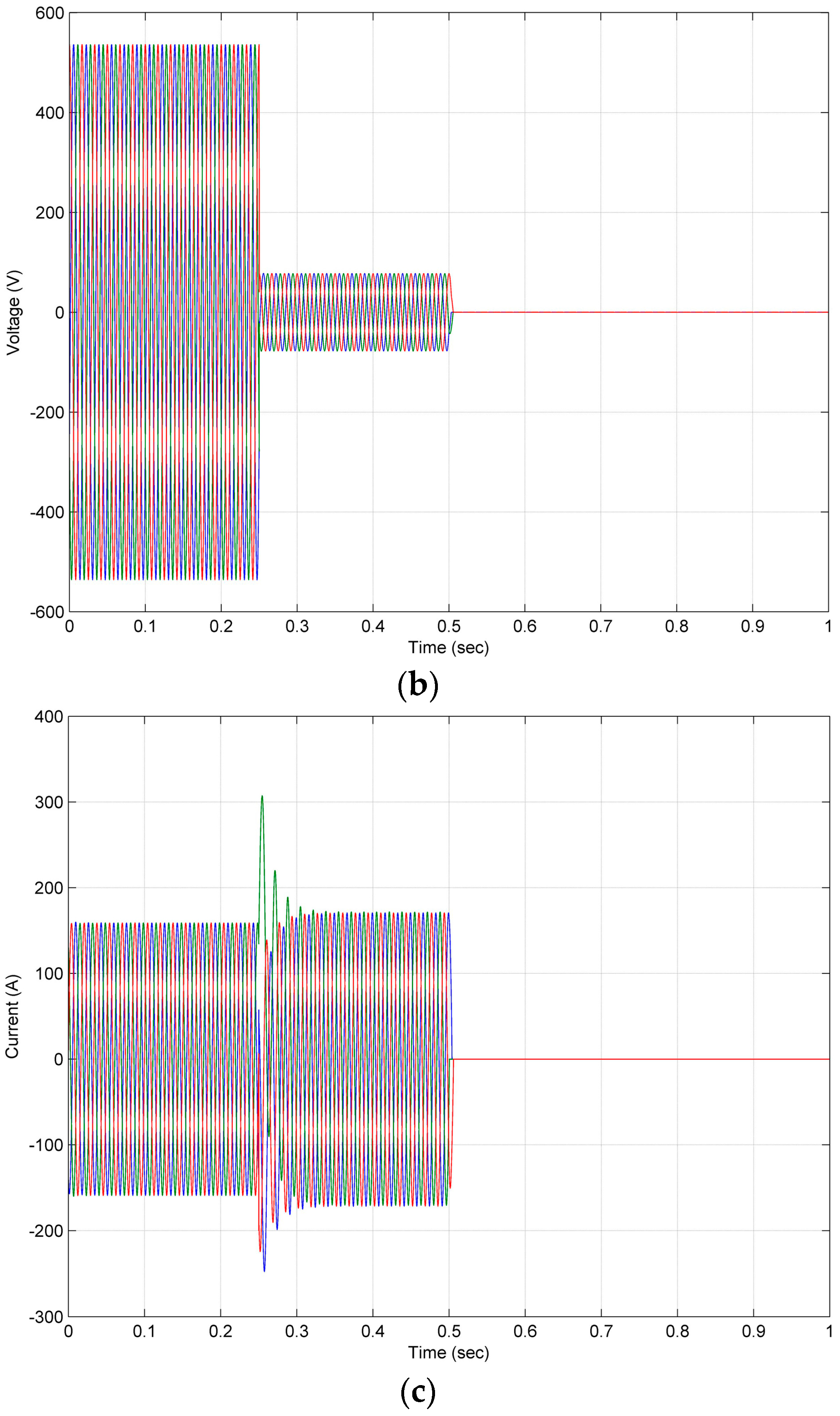
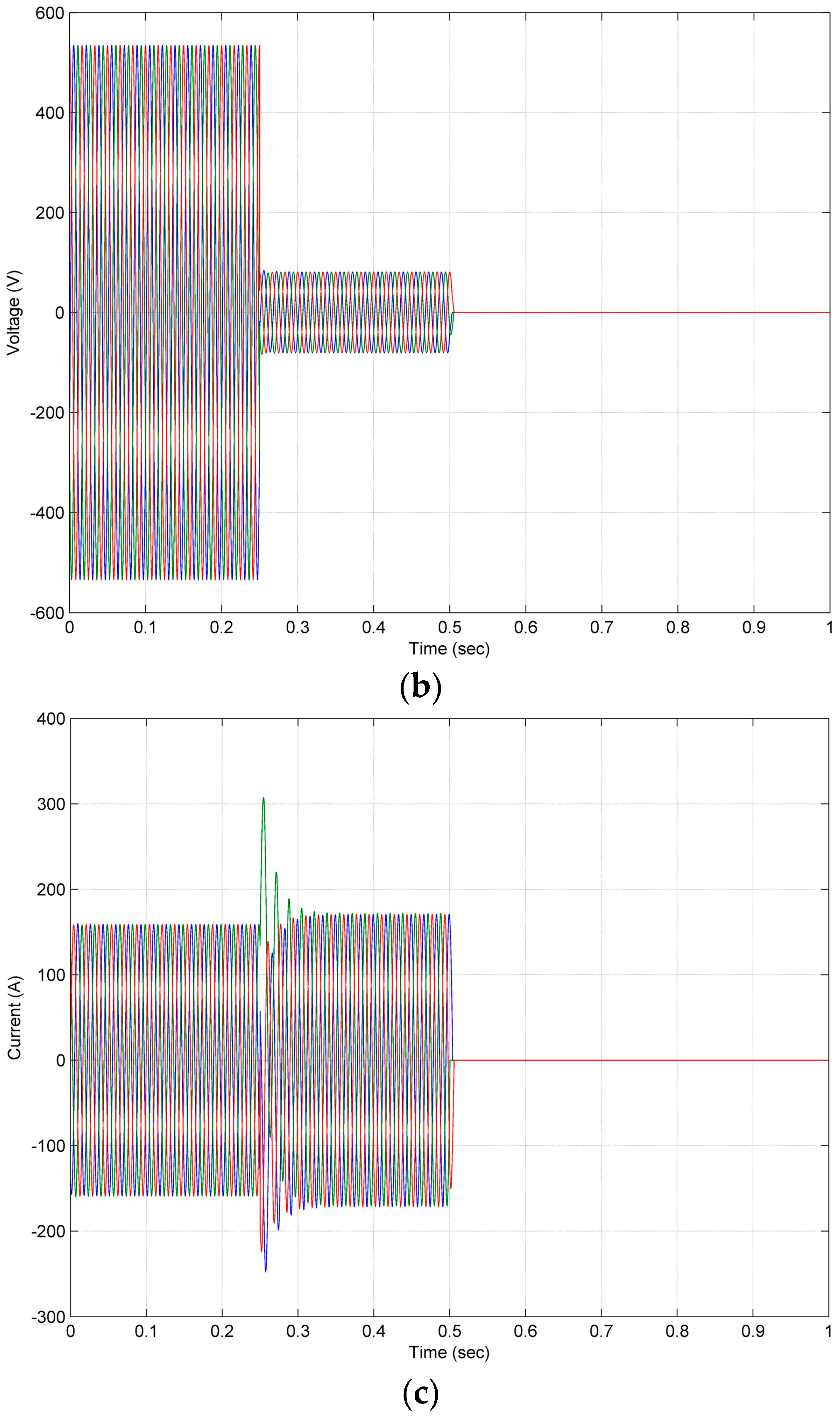
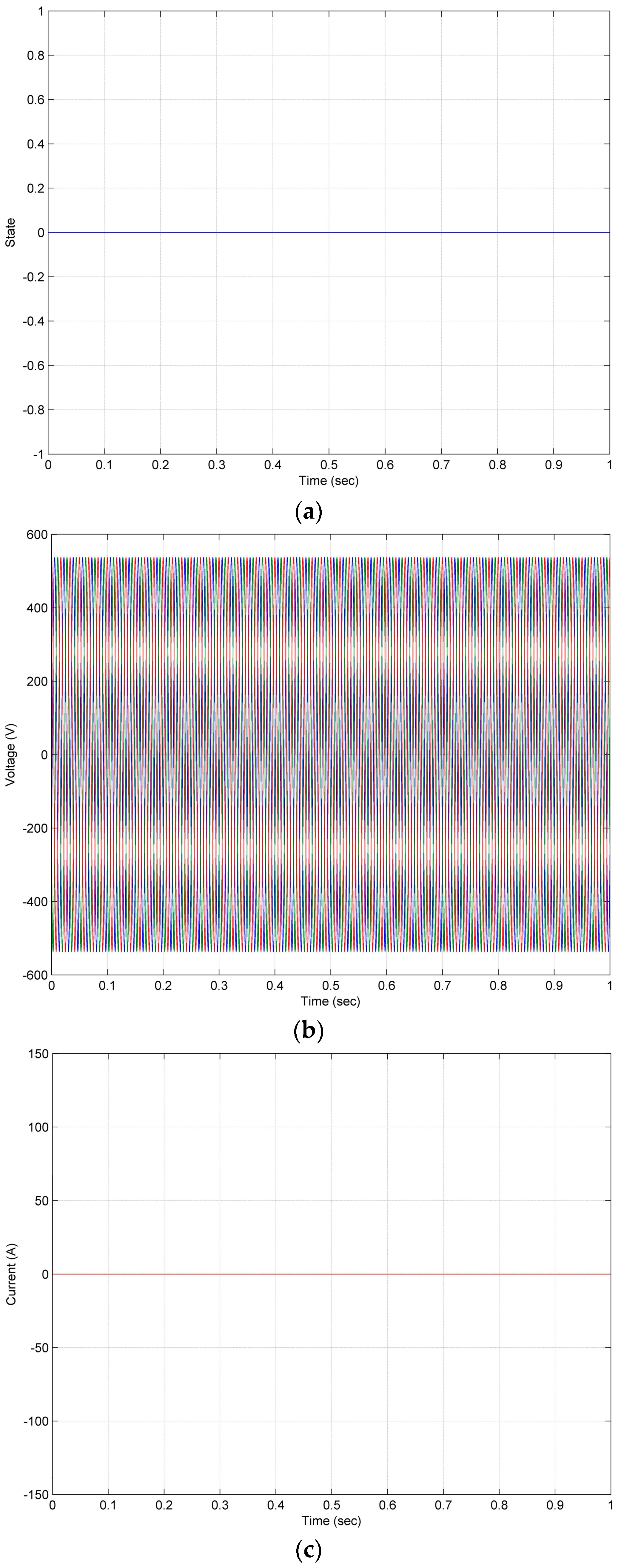
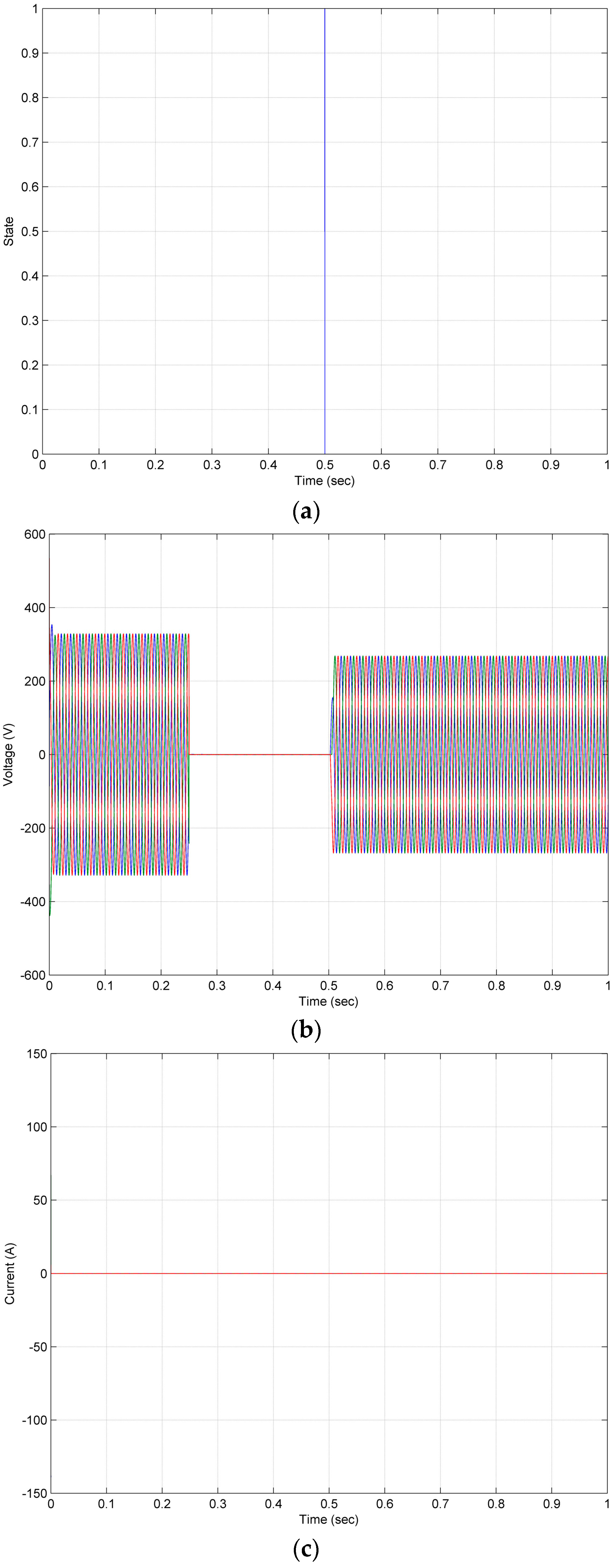
4. Simulation Results and Analysis

The feasibility and effectiveness of the proposed multi-agent technology applied on a microgrid for protection coordination were simulated and verified by the Zone 1 of the microgrid system that is located in the Institute of Nuclear Energy Research (INER) of Taoyuan, Taiwan. The single line diagram of the test microgrid system is shown in Figure 6.
The tripping and closing of each CB in Zone 1 is controlled by its corresponding CB agent. When a three-phase solid fault occurs in the test system, depending on the pick-up current (Ip), the CB agents will issue the tripping signals to their corresponding CBs. The Ip listed in Table 2 is calculated under normal operations of grid-connected and islanded modes for all CBs closing.
In grid-connected mode, the operations of the PV generation system (HCPV, PV), energy storage system (PCS100), and micro-turbine (μT) are in generating mode, charging mode, and standby mode, respectively. When a bolted three-phase fault occurs at Bus 1, the CB agent A9 will issue a trip command to CB9 and make CB9 trip. In addition, the communication between CB agents A9 and A10 will make CB10 trip. Meanwhile the CB agent A10 send a message back to CB agent A9 to confirm that a trip command has been issued to CB10. In the studied test microgrid system, the fault occurs at 0.25 s and the CBs trip at 0.5 s. Figure 7 shows the CLOSE/TRIP state and feeder voltage and current waveforms of CB9. Moreover, Figure 8 shows the CLOSE/TRIP state and feeder voltage and current waveforms of CB10. The interactive communication of the agents is shown in Figure 9. In contrast, if the CB10 fails to trip under the fault case, CB agent A10 will send the fail trip message to CB agent A9. CB agent A9 will issue a trip command to CB agent A11 and make CB11 trip. Meanwhile the CB agent A11 will send a message to CB agent A9 to confirm that a trip command has been issued to CB11. Figure 10 shows the CLOSE/TRIP state and feeder voltage and current waveforms of CB10. Moreover, the CLOSE/TRIP state and feeder voltage and current waveforms of CB11 are shown in Figure 11. In this case, the interactive communication of the agents is shown in Figure 12.
In islanded mode, the operations of the PV generation module (HCPV, PV), energy storage system (PCS100), and micro-turbine (μT) are in generating mode, discharging mode, and generating mode, respectively. Consider a bolted three-phase fault occurrence at Bus 2, CB agents A14 and A15 will issue a trip command to trip CB14 and CB15, respectively. In addition, the communication among CB agents A14, A11 and A1 will make CB11 and CB1 trip. Then CB agents A11 and A1 send the message to CB agent A14 to confirm that the trip command has been issued to CB11 and CB1. The other CBs are in close state, and operate in normal conditions. Regarding the CB9, there is no current through CB9, and CB9 is always in open state. Calculating the value of pick-up current in IED 9 is redundant. Figure 13 shows the CLOSE/TRIP state and feeder voltage and current waveforms of CB9. As mentioned above, the fault occurs at 0.25 s and the CBs trip at 0.5 s. Figure 14, Figure 15, Figure 16 and Figure 17 show the CLOSE/TRIP states and feeder voltage and current waveforms of CB11, CB1, CB14 and CB15, respectively. The interactive communication of the agents is shown in Figure 18.

5. Conclusions

A novel fault protection scheme has been proposed for the protection of microgrids in both of grid-connected and islanded operation modes. The model of the test microgrid system based on multi-agents was established in MATLAB/Simulink and the MAS was built by JADE. This paper introduced a new topology identification method that made MAS well suited for fault protection coordination and control of microgrids. Even if the topology of the microgrid is subject to variation, the proposed approach can identify the variation. Agent interaction, coordination and cooperation were discussed in the context of simulation results and analysis. The application of MAS in microgrids for symmetrical fault isolation has been clearly illustrated with the test microgrid system from INER in Taoyuan, Taiwan. The proposed approach is also adequate to protect from other fault types like single line to ground, line to line, and double line to ground. However, a delay time of CB operation was observed in this work. The main reason for the time delay is that all the sixteen agents’ actions were performed by only one computer. Additionally, the data exchange between MATLAB/Simulink and JADE platforms and some problems concerning TCP/IP communication will cause delays. The delay time will be substantially reduced if such issues can be solved.

Acknowledgments

This research was supported by the Institute of Nuclear Energy Research (INER), Atomic Energy Council (AEC), Taiwan under Grant NL1030943 (associated with the project, “The Development of Protection Management System (PMS)-based Protection Technology for Microgrids”).

Author Contributions

Jyh-Cherng Gu and Stephanus Antonius Ananda contributed in research idea; Stephanus Antonius Ananda and Jun-Da Chen conceived and designed the simulations; Jun-Da Chen performed the simulations; Stephanus Antonius Ananda, Ming-Ta Yang and Jun-Da Chen analyzed the data; Jyh-Cherng Gu and Ming-Ta Yang managed the whole research project; Jing-Min Wang provided for commenting on the early draft; Stephanus Antonius Ananda, Ming-Ta Yang and Jing-Min Wang worked together to write and revise the manuscript. Yung-Ruei Chang, Yih-Der Lee, Chen-Min Chan, and Chia-Hao Hsu are microgrids experts from INER (Institute of Nuclear Energy Research), Atomic Energy Council (AEC), Taiwan. They provide facilities, finance and expertise advisory in the microgrid field for the project.

Conflicts of Interest

The authors declare no conflict of interest.

Nomenclature

ACAgent Code
BMBase Matrix
CBCircuit Breaker
CMConversion Matrix
DERDistributed Energy Resource
FIPAFoundation for Intelligent Physical Agents
HCPVHigh Concentrator Photovoltaics
IEDIntelligent Electronic Devices
INERInstitute Nuclear Energy Research (in Taoyuan, Taiwan)
IpPick-up Current
JADEJava Agent Development Framework
MASMulti-Agent System
NTPNetwork Topology Processor
PVPhotovoltaics
TCBTripped-CB Number
TCB.aTripped-CB Number Side “a”
TCB.bTripped-CB Number Side “b”
TMTopology Matrix
μTMicro-Turbine

References

  1. Gu, J.-C.; Yang, M.-T.; Chen, J.-D.; Chung, H.-Y.; Wang, C.-Y.; Chang, Y.-R.; Lee, Y.-D.; Chan, C.-M.; Hsu, C.-H. Application of multi-agent systems to microgrid fault protection coordination. In Proceedings of the 2016 International Symposium on Computer, Consumer and Control (IS3C), Xi’an, China, 4–6 July 2016; pp. 188–191.
  2. Zeng, X.; Li, K.K.; Chan, W.L.; Su, S. Multi-agents based protection for distributed generation systems. In Proceedings of the 2004 IEEE International Conference on Electric Utility Deregulation, Restructuring and Power Technologies, Honkong, China, 5–8 April 2004; pp. 393–397.
  3. Logenthiran, T.; Srinivasan, D.; Khambadkone, A.; Aung, H. Scalable multi-agent system (MAS) for operation of a microgrid in islanded mode. In Proceedings of the 2010 Joint International Conference on Power Electronics, Drives and Energy Systems (PEDES) & 2010 Power, New Delhi, India, 20–23 December 2010; pp. 1–6.
  4. Aung, H.N.; Khambadkone, A.; Srinivasan, D.; Logenthiran, T. Agent-based intelligent control for real-time operation of a microgrid. In Proceedings of the 2010 Joint International Conference on Power Electronics, Drives and Energy Systems (PEDES) & 2010 Power, New Delhi, India, 20–23 December 2010; pp. 1–6.
  5. Macken, K.J.; Bollen, M.H.; Belmans, R.J. Mitigation of voltage dips through distributed generation systems. In Proceedings of the 38th IAS Annual Meeting Record of the Industry Applications Conference, Salt Lake, UT, USA, 12–16 October 2003; pp. 1068–1074.
  6. Kang, H.-K.; Chung, I.-Y.; Moon, S.-I. Voltage control method using distributed generators based on a multi-agent system. Energies 2015, 8, 14009–14025. [Google Scholar] [CrossRef]
  7. Zhang, J.; Ai, Q.; Jiang, C.; Wang, X.; Zheng, Z.; Gu, C. The application of multi agent system in microgrid coordination control. In Proceedings of the 2009 International Conference on Sustainable Power Generation and Supply, Nanjing, China, 6–7 April 2009; pp. 1–6.
  8. Eddy, F.Y.; Gooi, H. Multi-agent system for optimization of microgrids. In Proceedings of the 2011 IEEE 8th International Conference on Power Electronics and ECCE Asia (ICPE & ECCE), Jeju, Korea, 30 May–3 June 2011; pp. 2374–2381.
  9. Kantamneni, A.; Brown, L.E.; Parker, G.; Weaver, W.W. Survey of multi-agent systems for microgrid control. Eng. Appl. Artif. Intell. 2015, 45, 192–203. [Google Scholar] [CrossRef]
  10. Logenthiran, T.; Srinivasan, D.; Khambadkone, A.; Aung, H. Multi-agent system (mas) for short-term generation scheduling of a microgrid. In Proceedings of the 2010 IEEE International Conference on Sustainable Energy Technologies (ICSET), Kandy, Sri Lanka, 6–9 December 2010; pp. 1–6.
  11. Zheng, W.-D.; Cai, J.-D. A multi-agent system for distributed energy resources control in microgrid. In Proceedings of the 2010 5th International Conference on Critical Infrastructure (CRIS), Beijing, China, 20–22 September 2010; pp. 1–5.
  12. Logenthiran, T.; Srinivasan, D.; Wong, D. Multi-agent coordination for der in microgrid. In Proceedings of the 2008 IEEE International Conference on Sustainable Energy Technologies, Singapore, 24–27 November 2008; pp. 77–82.
  13. Dou, X.; Quan, X.; Wu, Z.; Hu, M.; Yang, K.; Yuan, J.; Wang, M. Hybrid multi-agent control in microgrids: Framework, models and implementations based on iec 61850. Energies 2014, 8, 31–58. [Google Scholar] [CrossRef]
  14. Li, C.; Savaghebi, M.; Guerrero, J.M.; Coelho, E.A.; Vasquez, J.C. Operation cost minimization of droop-controlled ac microgrids using multiagent-based distributed control. Energies 2016, 9, 717. [Google Scholar] [CrossRef]
  15. Lim, Y.; Kim, H.-M.; Kinoshita, T. Distributed load-shedding system for agent-based autonomous microgrid operations. Energies 2014, 7, 385–401. [Google Scholar] [CrossRef]
  16. Cha, H.-J.; Won, D.-J.; Kim, S.-H.; Chung, I.-Y.; Han, B.-M. Multi-agent system-based microgrid operation strategy for demand response. Energies 2015, 8, 14272–14286. [Google Scholar] [CrossRef]
  17. Logenthiran, T.; Naayagi, R.T.; Woo, W.L.; Phan, V.-T.; Abidi, K. Intelligent control system for microgrids using multiagent system. IEEE J. Emerg. Sel. Top. Power Electron. 2015, 3, 1036–1045. [Google Scholar] [CrossRef]
  18. Eddy, Y.F.; Gooi, H.B.; Chen, S.X. Multi-agent system for distributed management of microgrids. IEEE Trans. Power Syst. 2015, 30, 24–34. [Google Scholar] [CrossRef]
  19. Sachdev, M.; Sidhu, T.; Talukdar, B. Topology detection for adaptive protection of distribution networks. In Proceedings of the 1995 International Conference on Energy Management and Power Delivery (EMPD’95), Singapore, 21–23 November 1995; pp. 445–450.
  20. Pandit, S.; Soman, S.A.; Khaparde, S.A. Object-oriented network topology processor power system automation. IEEE Comput. Appl. Power 2001, 14, 42–46. [Google Scholar] [CrossRef]
  21. Piereti, S.A.R.; Delbem, A.C.B.; London, J.B.A.; Bretas, N.G. Tracking network topology processor using node-depth representation. In Proceedings of the 2007 IEEE Lausanne Power Tech, Lausanne, Switzerland, 1–5 July 2007; pp. 143–148.
  22. Prais, M.; Bose, A. A topology processor that tracks network modifications. IEEE Trans. Power Syst. 1988, 3, 992–998. [Google Scholar] [CrossRef]
  23. Rui, S.; Zhongyu, W.; Centeno, V.A. Power system islanding detection & identification using topology approach and decision tree. In Proceedings of the 2011 IEEE Power and Energy Society General Meeting, Detroit, MI, USA, 24–29 July 2011; pp. 1–6.
  24. Yajing, G.; Zhanlong, Z.; Wenchuan, W.; Haifeng, L. A method for the topology identification of distribution system. In Proceedings of the 2013 IEEE, Power and Energy Society General Meeting (PES), Vancouver, BC, Canada, 21–25 July 2013; pp. 1–5.
  25. Arghandeh, R.; Gahr, M.; von Meier, A.; Cavraro, G.; Ruh, M.; Andersson, G. Topology detection in microgrids with micro-synchrophasors. In Proceedings of the 2015 IEEE Power & Energy Society General Meeting, Denver, CO, USA, 26–30 July 2015; pp. 1–5.
Figure 1. Construct TM model. (a) Example network; (b) CB model; (c) TM; (d) Topology graph.
Energies 10 00028 g001
Figure 2. Update TM model for CB2 trip. (a) New TM; (b) Topology graph.
Energies 10 00028 g002
Figure 3. Conversion of TM into the Ybus Matrix. (a) TM; (b) Conversion Matrix (CM); (c) Base Matrix (BM); (d) Conversion Table; (e) Modified Base Matrix; (f) Computation the first diagonal element of the YBus Matrix; (g) Computation of the remaining elements of the YBus Matrix; (h) YBus Matrix.
Energies 10 00028 g003aEnergies 10 00028 g003b
Figure 4. Flowchart for implementation of proposed fault protection for MAS-based microgrid control.
Energies 10 00028 g004
Figure 5. Diagram of the interface between Matlab/Simulink and JADE.
Energies 10 00028 g005
Figure 6. Single line diagram of the test microgrid system with MAS.
Energies 10 00028 g006
Figure 7. (a) CB9 CLOSE/TRIP state; (b) Feeder voltage waveforms of CB9 under grid-connected mode and fault occurrence at Bus 1; (c) Feeder current waveforms of CB9 under grid-connected mode and fault occurrence at Bus 1.
Energies 10 00028 g007
Figure 8. (a) CB10 CLOSE/TRIP state; (b) Feeder voltage waveforms of CB 10 under grid-connected mode and fault occurrence at Bus 1; (c) Feeder current waveforms of CB 10 under grid-connected mode and fault occurrence at Bus 1.
Energies 10 00028 g008
Figure 9. Interactive communication of the agents under grid-connected mode and fault occurrence at Bus 1.
Energies 10 00028 g009
Figure 10. (a) CB10 CLOSE/TRIP state; (b) Feeder voltage waveforms of CB10 under grid-connected mode, fault occurrence at Bus 1 and failure trip of CB10; (c) Feeder current waveforms of CB10 under grid-connected mode, fault occurrence at Bus 1 and failure trip of CB10.
Energies 10 00028 g010aEnergies 10 00028 g010b
Figure 11. (a) CB11 CLOSE/TRIP state; (b) Feeder voltage waveforms of CB11 under grid-connected mode, fault occurrence at Bus 1 and failure trip of CB10; (c) Feeder current waveforms of CB11 under grid-connected mode, fault occurrence at Bus 1 and failure trip of CB10.
Energies 10 00028 g011aEnergies 10 00028 g011b
Figure 12. Interactive communication of the agents under grid-connected mode, fault occurrence at Bus 1 and failure trip of CB10.
Energies 10 00028 g012
Figure 13. (a) CB9 CLOSE/TRIP state; (b) Feeder voltage waveforms of CB9 under islanded mode and fault occurrence at Bus 2; (c) Feeder current waveforms of CB9 under islanded mode and fault occurrence at Bus 2.
Energies 10 00028 g013
Figure 14. (a) CB11 CLOSE/TRIP state; (b) Feeder voltage waveforms of CB11 under islanded mode and fault occurrence at Bus 2; (c) Feeder current waveforms of CB11 under islanded mode and fault occurrence at Bus 2.
Energies 10 00028 g014
Figure 15. (a) CB1 CLOSE/TRIP state; (b) Feeder voltage waveforms of CB1 under islanded mode and fault occurrence at Bus 2; (c) Feeder current waveforms of CB1 under islanded mode and fault occurrence at Bus 2.
Energies 10 00028 g015
Figure 16. (a) CB14 CLOSE/TRIP state; (b) Feeder voltage waveforms of CB14 under islanded mode and fault occurrence at Bus 2; (c) Feeder current waveforms of CB14 under islanded mode and fault occurrence at Bus 2.
Energies 10 00028 g016
Figure 17. (a) CB15 CLOSE/TRIP state; (b) Feeder voltage waveforms of CB15 under islanded mode and fault occurrence at Bus 2; (c) Feeder current waveforms of CB15 under islanded mode and fault occurrence at Bus 2.
Energies 10 00028 g017
Figure 18. Interactive communication of the agents under islanded mode and fault occurrence at Bus 2.
Energies 10 00028 g018
Table 1. Agent code.
CodeConnection Node Type
1Line
2Generator (G)
3Load (L)
4Bus (B)
0Others
Table 2. Pick-up current for IEDs.
IEDPick-Up Current (Unit: A)
Grid-Connected ModeIslanded Mode
13358.9990.58
2135.1583.41
33070.5592.15
43070.5592.15
545.9852.12
645.9852.12
745.9852.12
8135.0783.55
912,789.67-
108818.15141.35
118818.15141.35
1274.0483.16
133358.9990.58
146312.7892.08
156312.7892.08

