
Wireless DC Motor Drives with Selectability and Controllability


1
Department of Electrical and Electronic Engineering, The University of Hong Kong, Hong Kong, China
2
School of Energy and Environment, City University of Hong Kong, Hong Kong, China
*
Author to whom correspondence should be addressed.
Energies 2017, 10(1), 49; https://doi.org/10.3390/en10010049
Submission received: 7 November 2016
/
Revised: 20 December 2016
/
Accepted: 26 December 2016
/
Published: 4 January 2017
(This article belongs to the Special Issue Wireless Power Transfer 2016)
Abstract
:This paper proposes and implements the concept of wireless DC motor drives, which can achieve the abilities of selective driving and controllable speed. Due to different resonant frequencies of the multiple energy receivers of the associated DC motor drives, the transmitter can be purposely tuned to the specified resonant frequency which matches with the specified receiver, hence driving the specified motor selectively. In the meantime, the burst fire control is used to regulate the operating speed of the motor working at the resonant frequency, hence retaining the maximum power transmission efficiency. Both finite element analysis and experimentation are given to verify the validity of the proposed wireless DC motor drive system. For exemplification, three different resonant frequencies, namely 60 kHz, 100 kHz and 140 kHz, are selected to energize three DC motors. Under the burst fire control method, the speed of each motor can be regulated separately and the wireless power transfer (WPT) system can achieve the measured power transmission efficiency of about 60%.
1. Introduction
Since Nikola Tesla pioneered wireless power transfer (WPT) with far and near fields more than one hundred years ago, considerable attention has been refocused on the application of WPT in recent years [1,2,3,4,5]. Based on the principle of magnetic resonant coupling, this WPT technique shows great potential for many applications, such as the implantable medical instruments [6,7], the non-accessible electronic devices [8,9], and the battery-powered electric vehicles [10,11,12].
For some practical applications, such as mobile phones [13] and medical devices [14], multiple-coil power transfer is often required [15,16]. In order to achieve higher feasibility and better flexibility for WPT, the development of simultaneous mid-range power transfer from a single transmitter to multiple receivers has been very active [17,18]. By employing different resonant frequencies, selective WPT to multiple receivers can be achieved [19]. However, the corresponding output power is controlled by tuning the operating frequency, which essentially causes the sacrifice of power transmission efficiency [20]. Meanwhile, the corresponding analysis is limited to resistive loads only, which cannot be applied to industrial applications such as conveyor control or robotic control.
The purpose of this paper is to propose and implement the wireless DC motor drive system. The key is to incorporate the concept of selective WPT into the multiple DC motor drive system so that each wireless DC motor drive can be selectively energized and controlled without sacrifice of power transmission efficiency. Firstly, the mathematical model of the proposed DC motor drive system will be derived, hence assessing its selective driving characteristics. Then, the burst fire control will be employed to regulate the WPT of each DC motor drive, hence achieving speed regulation under the maximum power transmission efficiency. Finally, both finite element analysis and experimentation will be conducted to verify the proposed system.
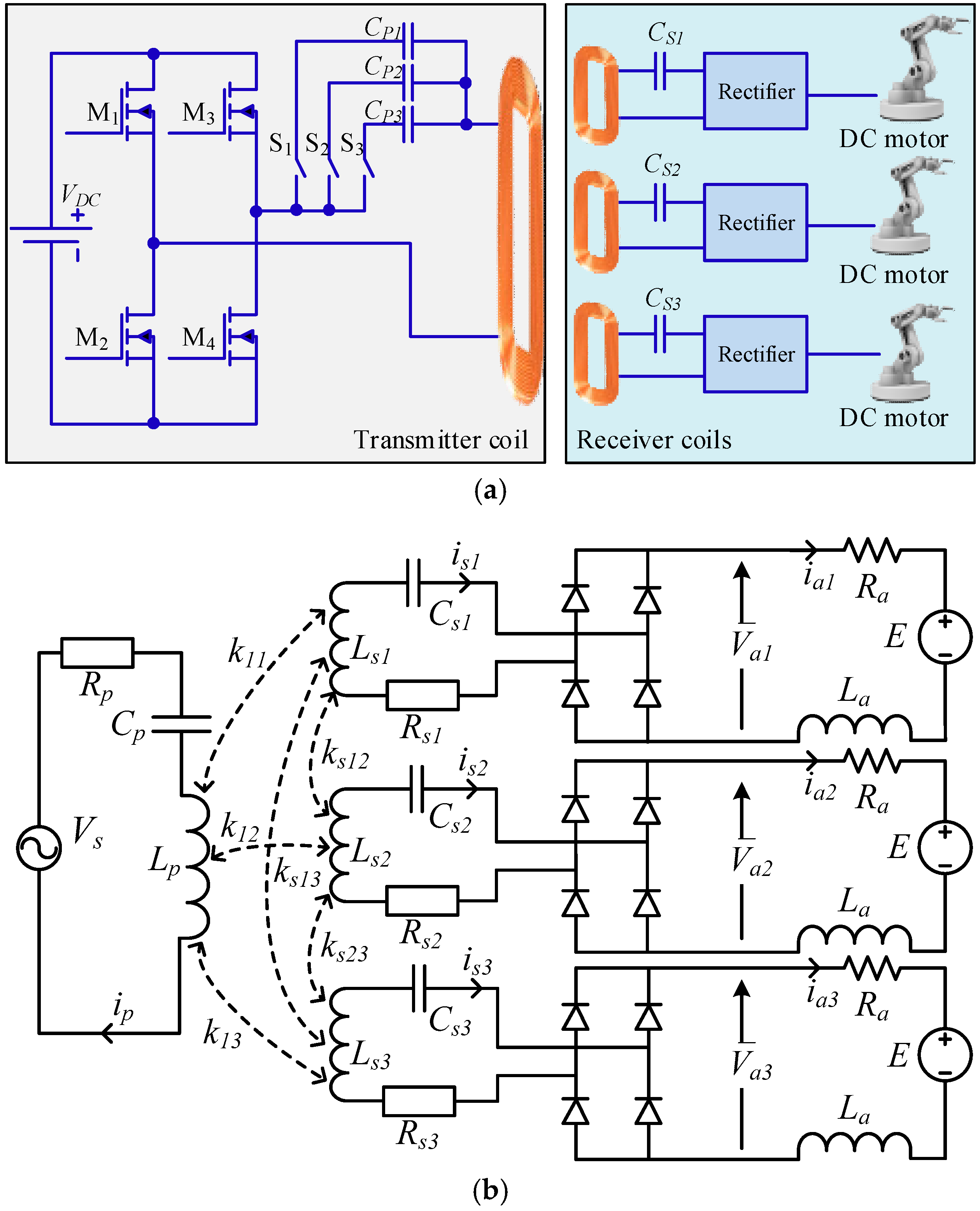
2. System Configuration
The structure of the proposed wireless DC motor drive system is shown in Figure 1, which consists of the full-bridge inverter to energize the transmitter (primary) coil, the switched capacitor array to tune the resonant frequency of the transmitter coil, the resonant capacitors connected in series with relevant receiver (secondary) coils to achieve different receiver resonant frequencies, the full-bridge rectifiers to perform AC–DC conversion for relevant DC motors, and the DC motors for various direct-drive applications.
3. System Design
The equivalent model of the proposed wireless DC motor drive system is shown in Figure 2b. The DC motor is represented by the armature resistance Ra, armature winding inductance La and the back electromotive force (EMF) E. In the meantime, Rp, Rs1, Rs2 and Rs3 are the resistances of the transmitter coil, the first receiver coil, the second receiver coil and the third receiver coil, respectively; Cp, Cs1, Cs2 and Cs3 are the resonant capacitances that are connected in series with the transmitter coil, the first receiver coil, the second receiver coil and the third receiver coil, respectively; and Lp, Ls1, Ls2 and Ls3 are the inductances of the transmitter coil, the first receiver coil, the second receiver coil and the third receiver coil, respectively.
Assuming that the resistance and forward voltage drop of diodes are negligible and La is sufficiently high that the corresponding current ripple can be ignored, the average armature current Iai of the DC motor i (i = 1, 2, 3) can be expressed as [21]:
where Isi is the RMS current of the receiver coil i.
Based on the principle of DC motor under the steady state, the electromagnetic torque T and E can be expressed as:
where K and Φ represent the torque constant and the air-gap flux per pole, respectively; and Ia and ωm are the armature current and motor speed, respectively.
It should be noted that k11, k12, and k13 are the coupling coefficients between the transmitter coil and various receiver coils, respectively. Since the receiver coils are on the same plane, their mutual inductances can be ignored. Thus, the mutual inductances between the transmitter coil and the receiver coils can be expressed as:
The motor will start to rotate when the armature current and hence the torque is larger than the load torque. The threshold of this armature current Ith can readily be calculated by first setting E equal to zero. Hence, the operating frequency range for WPT is to ensure that Ia is larger than Ith.
Accordingly, the system model of the proposed wireless DC motor drive at the stationary mode can be expressed as:
where Zp, Zs1, Zs2 and Zs3 are given by:
The resonant frequencies of the transmitter and receiver coils are denoted as ω, ω1, ω2, and ω3, respectively, which are given by:
Assuming that the internal resistance of each receiver coil is the same, namely Rs1 = Rs2 = Rs3 = R, and the inductance of each receiver coil is the same, namely Ls1 = Ls2 = Ls3 = L, it results in M11 = M12 = M13 = M. Nevertheless, the capacitances in various receiver coils are not the same, namely Cs1 ≠ Cs2 ≠ Cs3. Hence, the threshold current Ithi at the receiver i can be calculated by:
When the transmitter resonant frequency ω is equal or close to ωi (i = 1, 2, 3), the corresponding Zsi becomes much smaller than that of the others so that the transmitter power can be selectively delivered to the targeted receiver coil of the DC motor. Therefore, the transmitter resonant frequency can be utilized to feed a particular receiver selectively based on different resonant frequencies. Consequently, the operating frequency range of each motor can be determined.
For exemplification, when motor 1 is selected to be energized, the motion equation is given by:
By combining Equations (2), (3), (9) and (10), Ip, the speed of motor 1 ωm1 and the power transmission efficiency η1 of motor 1 can be deduced as:
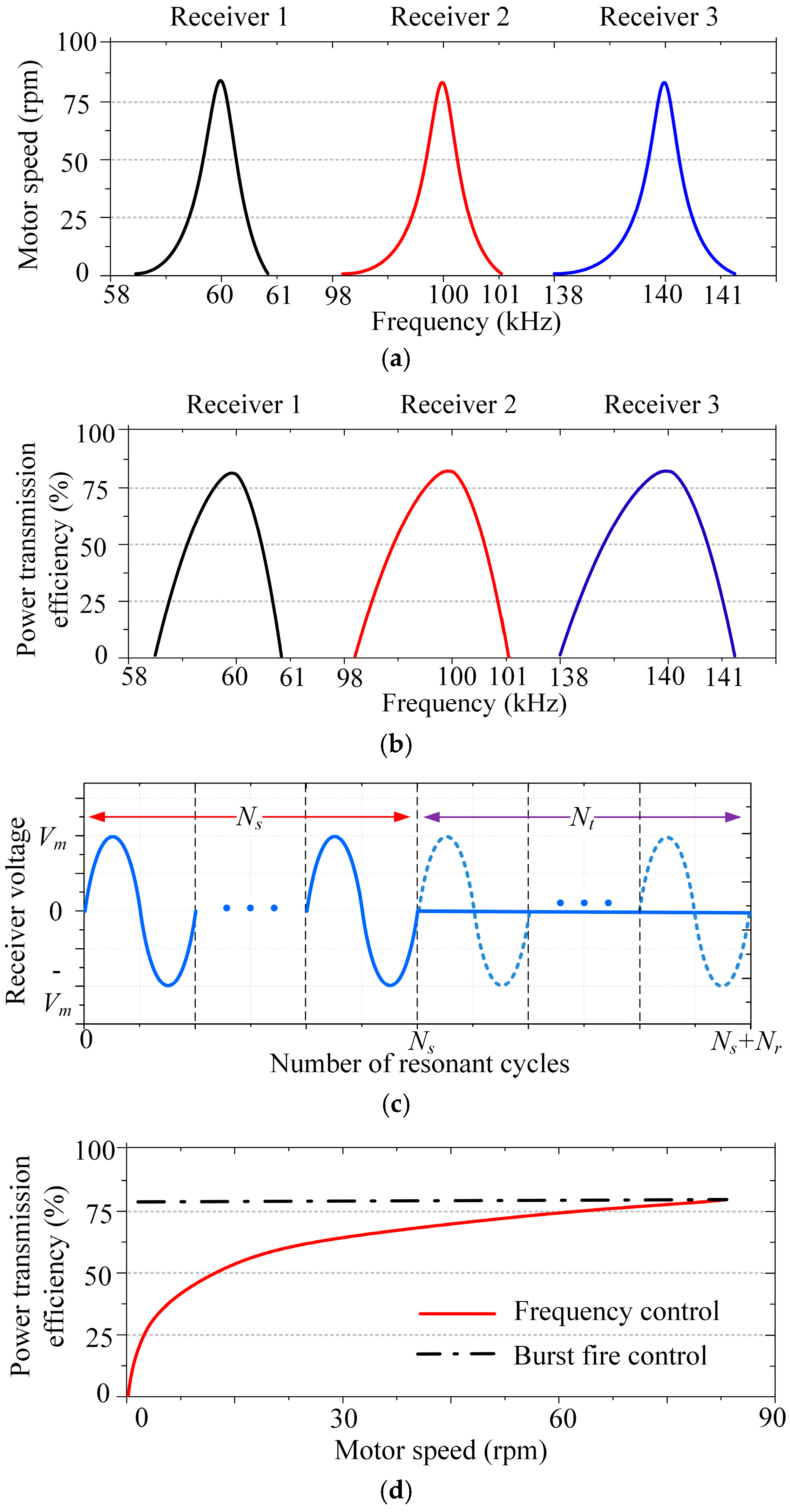
The key parameters of the proposed system are listed in Table 1. The resulting resonant frequencies of the receivers 1, 2 and 3 are 60 kHz, 100 kHz and 140 kHz, respectively. From Equations (12) and (13), the resulting motor speeds and power transmission efficiencies with respect to these operating frequencies are calculated as shown in Figure 2a,b, respectively. It can be observed that each wireless DC motor can be successfully selected without ambiguity.
The power transfer from the transmitter to each receiver can be regulated by varying the operating frequency around the relevant resonant point. However, this regulation method inevitably sacrifices the power transmission efficiency. In order to provide power regulation while maintaining the maximum power transmission efficiency, the burst fire control is employed. Namely, the operating frequencies of the transmitter and the targeted receiver are always the same and kept at the relevant resonant point, and the power transfer is controlled by the number of transmission cycles Nt with respect to the total number of transmission and idling cycles (Nt + Ni) as depicted in Figure 2c. As shown in Figure 2d, it can be observed that although the speed of the DC motor 2 can be adjusted by frequency control, it suffers from the sacrifice of power transmission efficiency; whereas the use of burst fire control can maintain the efficiency at its maximum value. The other two motors perform similarly. In the wireless DC drive system, the transferred power is controlled via the regulation of the duty ratio at the resonant frequency, which corresponds to the changes in motor speed with a fixed load. Thus, the control variable is the duty ratio δ:
Since the resonant frequency is very high, the transmission cycle is much shorter than that of the natural time constant of DC motors. Thus, each control cycle can accommodate many transmission and idling cycles so that the variation of the number of transmitting cycles can provide practically smooth control of power transfer.
4. Simulation Results
In order to assess the proposed wireless DC motor drive system, the system operation is simulated using the electromagnetic finite element analysis software JMAG-Designer (V12.0, JSOL, Tokyo, Japan) and the control software Matlab/Simulink (R2014b, MathWorks, Natick, MA, USA). Particularly, the selectability and controllability of the proposed system are evaluated. The key parameters of the transmitter coil and three receiver coils as listed in Table 1 are adopted for simulation. Meanwhile, the distance between the transmitter coil and the receiver coils is set at 50 mm.
4.1. Selectability of DC Motor
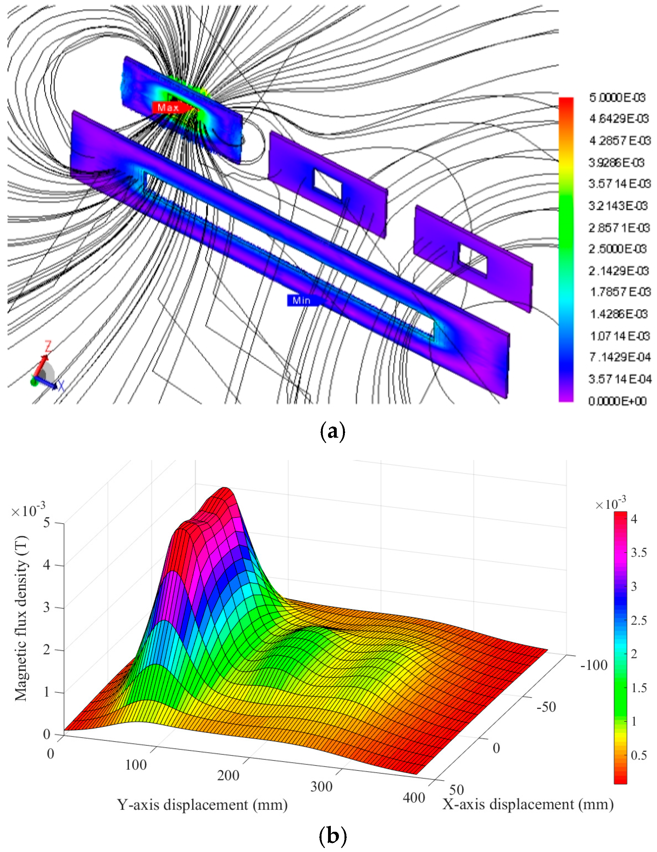
In order to assess the selectability of the proposed system, the resonant frequency of the transmitter is tuned to 60 kHz, 100 kHz and 140 kHz, aiming to selectively transfer power to receivers 1, 2 and 3, respectively. The simulated magnetic flux line distributions and magnetic flux density distributions at the resonant frequencies of 60 kHz, 100 kHz and 140 kHz are shown in Figure 3, Figure 4 and Figure 5, respectively. It can be observed that the flux lines essentially cluster at the left receiver (receiver 1), middle receiver (receiver 2) and right receiver (receiver 3) when the transmitter resonant frequency is tuned to 60 kHz, 100 kHz and 140 kHz, respectively. Meanwhile, the magnetic flux lines passing through the unselected coils are relatively sparse.
Additionally, the magnetic flux density distributions at the resonant frequencies of 60 kHz, 100 kHz and 140 kHz clearly indicate that the WPT from the transmitter to a particular receiver can be accurately selected. For instance, when the middle receiver is selected to pick up wireless power, the corresponding magnetic flux density can reach 2.67 mT at the resonant state, whereas the magnetic flux densities of other two receivers can only reach 0.0759 mT. Similar results can be found when the left receiver or right receiver is selected to pick up wireless power. Therefore, it confirms that the receiver can be selectively targeted to pick up the wireless power from the transmitter.
It should be that the maximum magnetic flux densities that can be picked up by the three receivers are slightly different as shown in Figure 3b, Figure 4b and Figure 5b. This is because the equivalent load impedance reflected to the transmitter increases with the resonant frequency, which leads to the reduction of magnetic flux and hence power transfer from the transmitter to the targeted receiver.
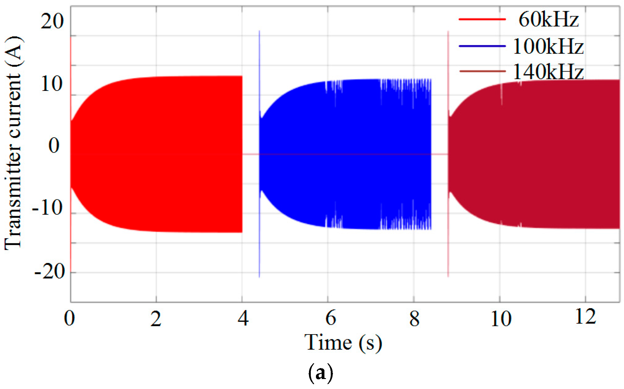
On top of the static selectability, the dynamic selectability of the proposed system is assessed by sequentially selecting the three DC motors. Namely, the resonant frequency of the transmitter is sequentially switched to 60 kHz, 100 kHz, and 140 kHz. Figure 6 shows the responses of transmitter current, motor torque and motor speed of the three DC motors. It illustrates that the DC motors can be selectively excited, which in turn generate the motor torque and accelerate to the rated speed sequentially.
As mentioned above, the power transfer to the targeted receiver slightly decreases with the increase of its resonant frequency, and vice versa, and the corresponding motor torque and speed vary accordingly, as depicted in Figure 6. Thus, speed control is necessary to enable the selected motor achieving the desired speed.
4.2. Controllability of DC Motor
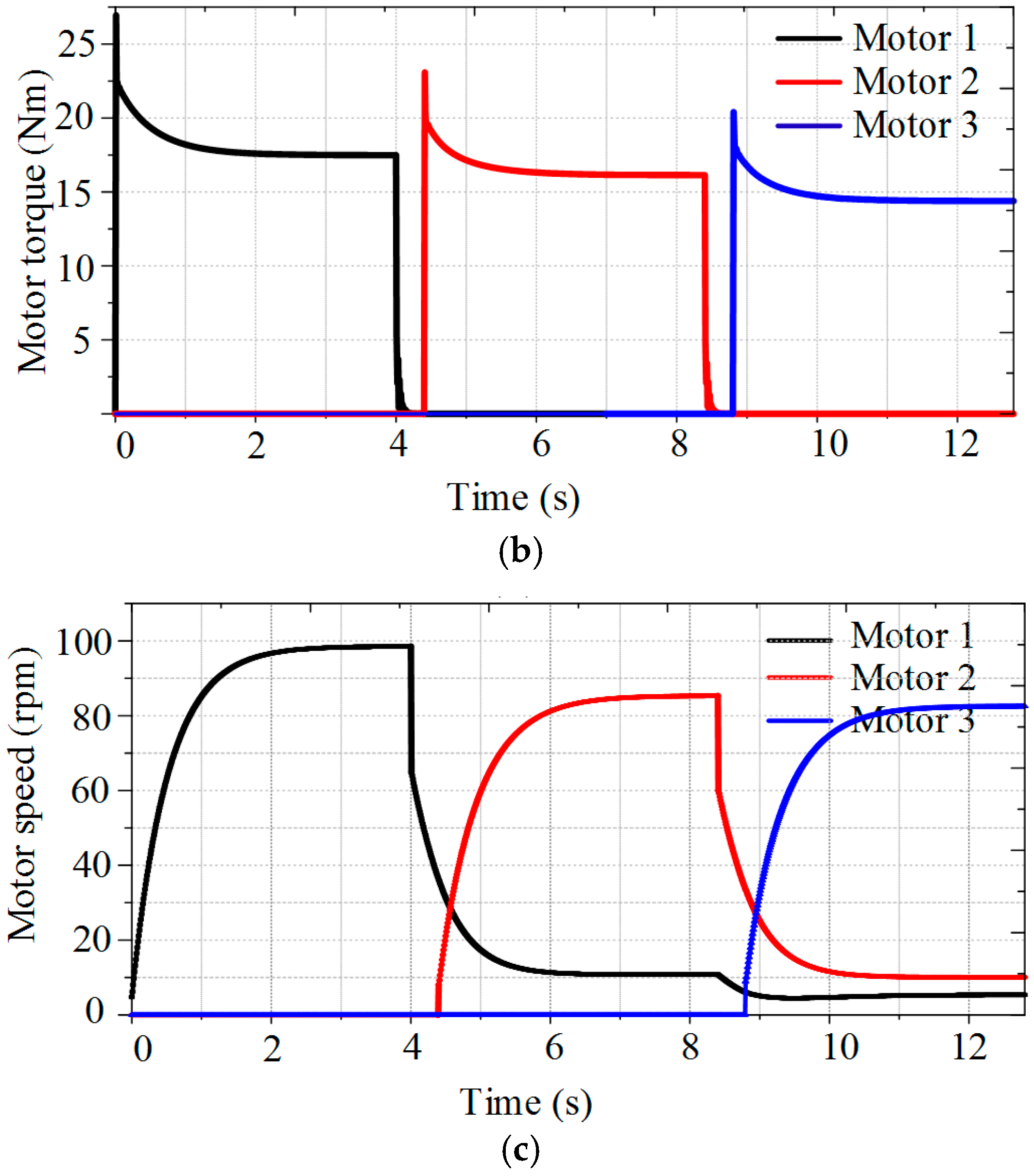
Once the resonant frequency of the transmitter is selected to perform WPT to the targeted receiver, the motor torque and speed of the targeted DC motor can readily be regulated through the adjustment of the operating frequency as shown in Figure 7. It can be observed that the motor torque and hence the motor speed can achieve the maximum values at the point of resonant frequency; meanwhile, the motor torque and speed can be regulated by varying the operating frequency. However, as depicted in Figure 2, the power transmission efficiency will deteriorate significantly if the operating frequency deviates from the resonant frequency.
Instead of performing the frequency control, the burst fire control is employed which can maintain the operating frequency always equal to the resonant frequency. Thus, the speed regulation of the DC motors can be performed while achieving the maximum transmission efficiency. It should be noted that the burst fire control was not attractive for classical DC motor control because the control cycle was relatively long and the control resolution was limited by a standard AC cycle. Fortunately, these drawbacks are automatically solved in this wireless DC motor control because the resonant frequency is so high that the transmission cycle and hence the control cycle are much shorter than that of the natural time constant of DC motors and there are many transmission cycles within a control cycle to enable high control resolution.
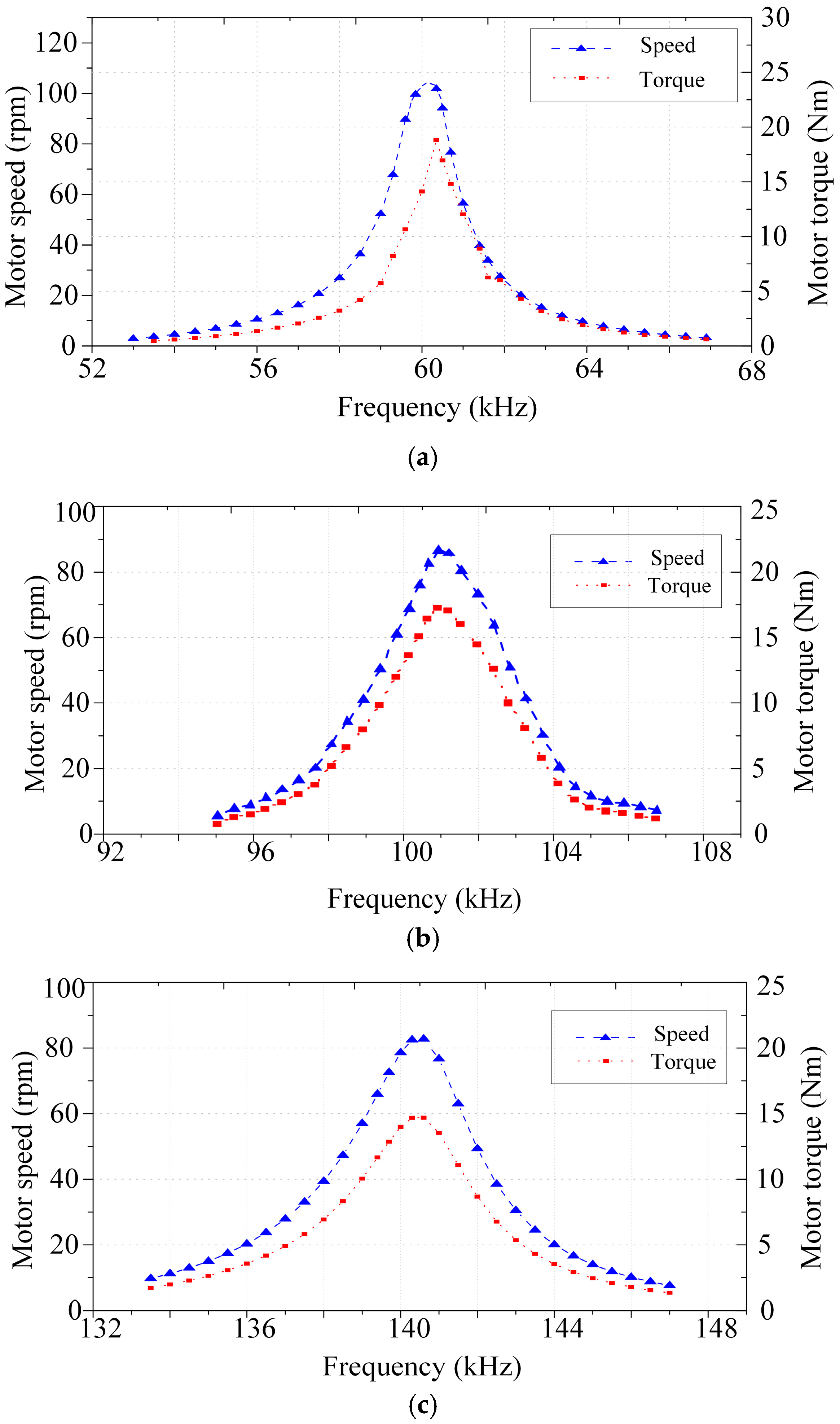
By applying the burst fire control to the proposed DC motor drive system, the control cycle is set to embrace at most 50 transmission cycles. The resulting motor torque and speed at the resonant frequencies of 60 kHz, 100 kHz and 140 kHz for the DC motor 1, 2 and 3, respectively, are plotted against the duty ratio as shown in Figure 8. The results show that the speed of the targeted DC motor can be regulated effectively within the speed range of 0–80 rpm. As aforementioned, the power transfers from the transmitter to the receivers are slightly different. This burst fire control can also be used to regulate this difference to enable the three DC motors achieving the same performance.
5. Experimental Results
For verification, the experimental setup of the proposed wireless DC motor drive system is established as shown in Figure 9. In the test bed, it consists of the programmable function generator to produce the desired AC waveform, the wideband power amplifier to produce the desired AC supply, the current sensors to measure the motor currents, the speed sensors to measure the motor speeds, the digital oscilloscope and PC to display various waveforms, the three DC motors, the transmitter and the three receivers.
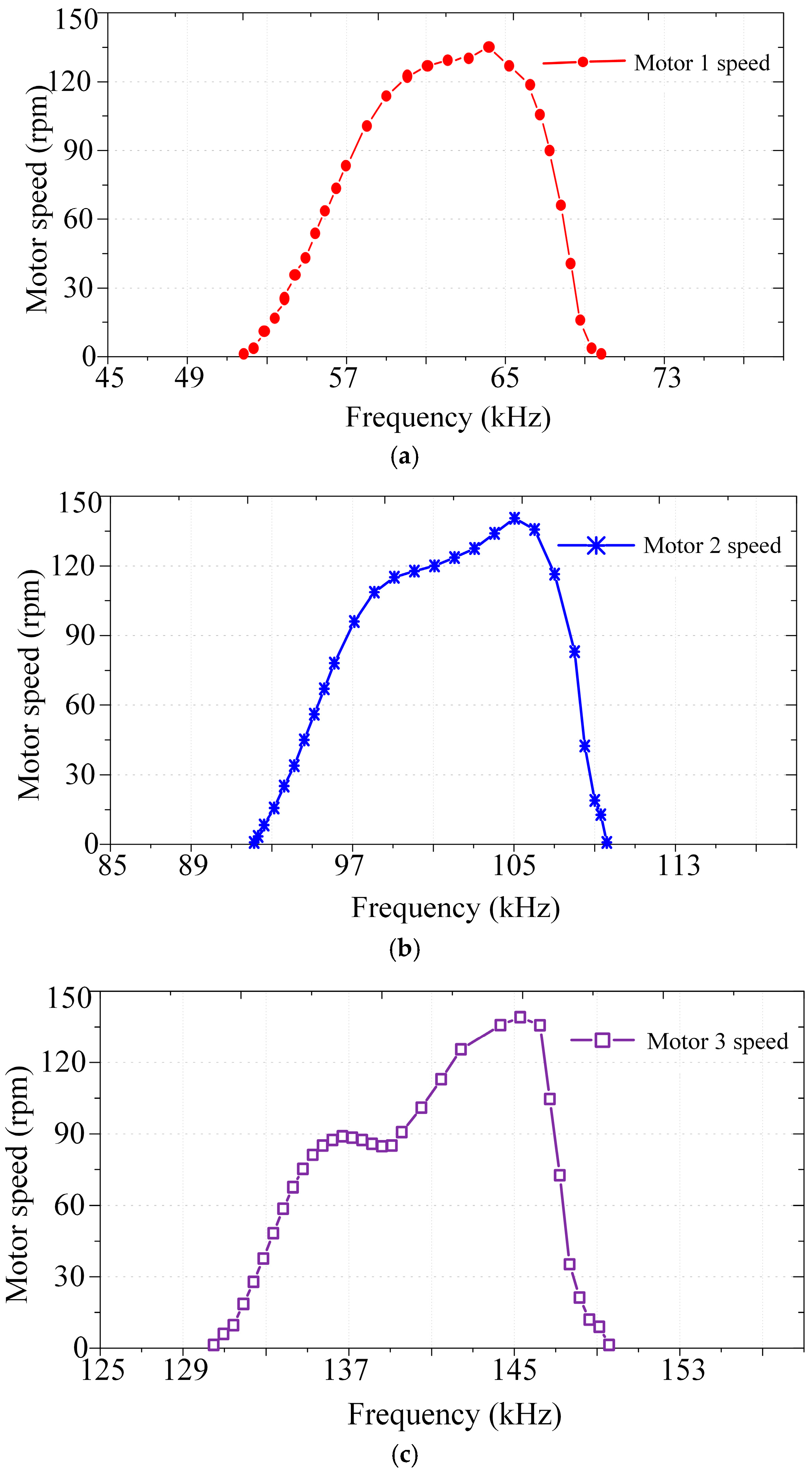
Firstly, the resonant frequency of the transmitter is set at 60 kHz, 100 kHz or 140 kHz, aiming to perform WPT to the DC motor 1, 2 or 3, respectively. Key parameters of the DC motors are listed as follows: the rated output power is 200 W, the rated speed is 500 rpm, the rated input voltage is 80 V, and the rated input current is 3.4 A. The operating frequency is tuned around the resonant frequencies to assess the variation of WPT and hence the motor speed. Under the constant load torque of near 1.5 Nm, the steady-state motor speeds of three DC motors are measured at different operating frequencies as plotted in Figure 10. It confirms that each DC motor can be successfully selected by the operating frequency, and there is no undesirable crosstalk between motors. Namely, only the targeted DC motor picks up the power to accelerate to the desired speed whereas the other two motors cannot pick up the power and keep standstill.
It can be observed that the resonant frequencies of the measured waveforms are not exactly equal to the desired values, which are actually due to the tolerance of the capacitor values. Meanwhile, the shapes of measured waveforms are not exactly sinusoidal and the deviation increases with the operating frequency. It is actually due to the parasitic inductances and capacitances, which are becoming noticeable at higher operating frequencies. Nevertheless, these parameter tolerance and parasitic components will not affect the selectivity of the targeted DC motor.
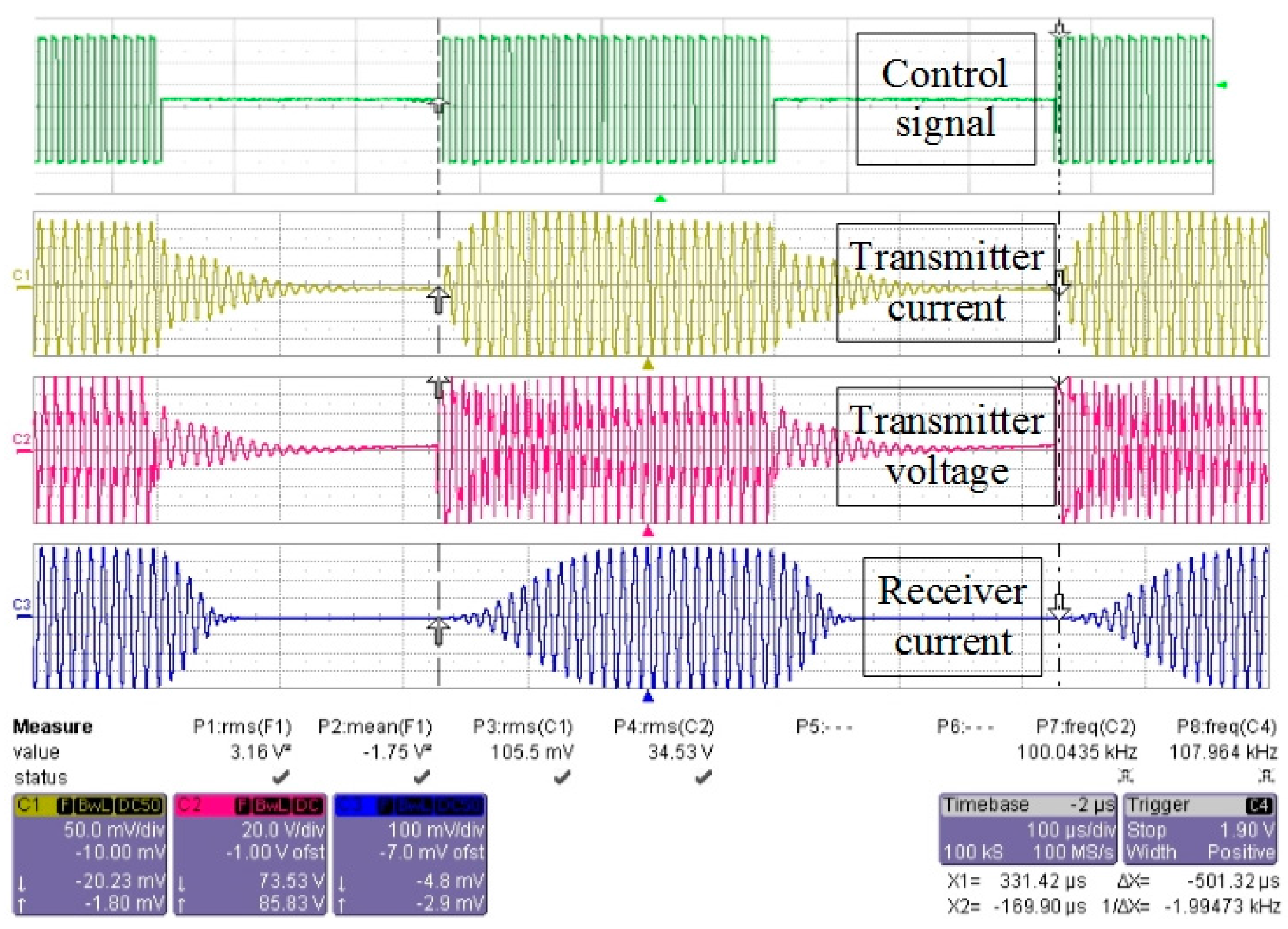
Once the targeted motor has been energized selectively, the speed regulation is assessed experimentally by using the burst fire control. Figure 11 shows the resulting waveforms when DC motor 2 is excited and the burst fire control adopts the duty ratio of 60% with the control cycle equal to 50 transmission cycles. It confirms that the burst fire control can work properly to regulate the WPT.
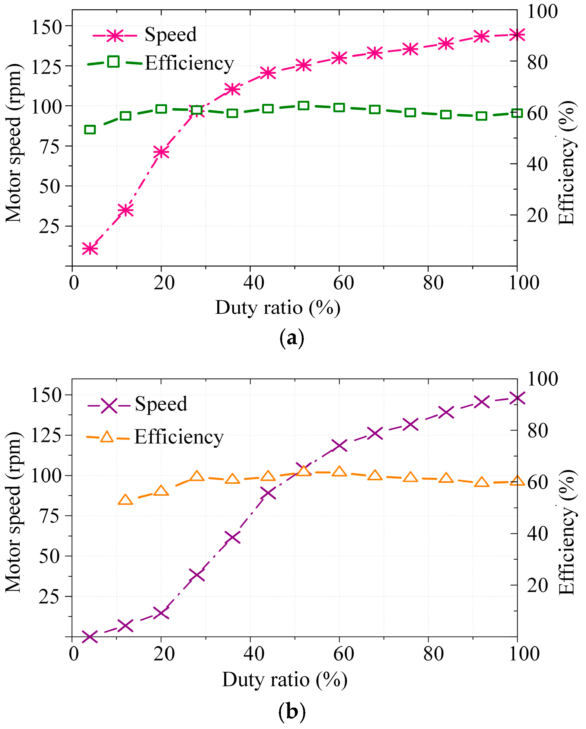
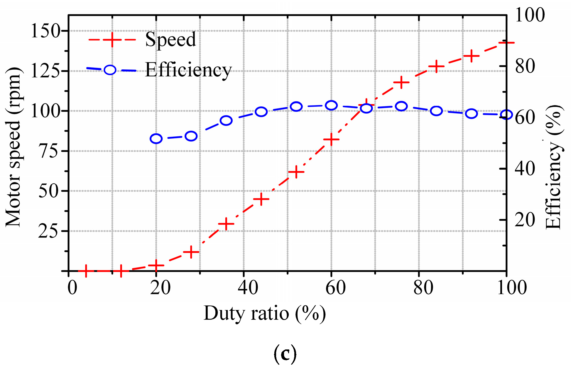
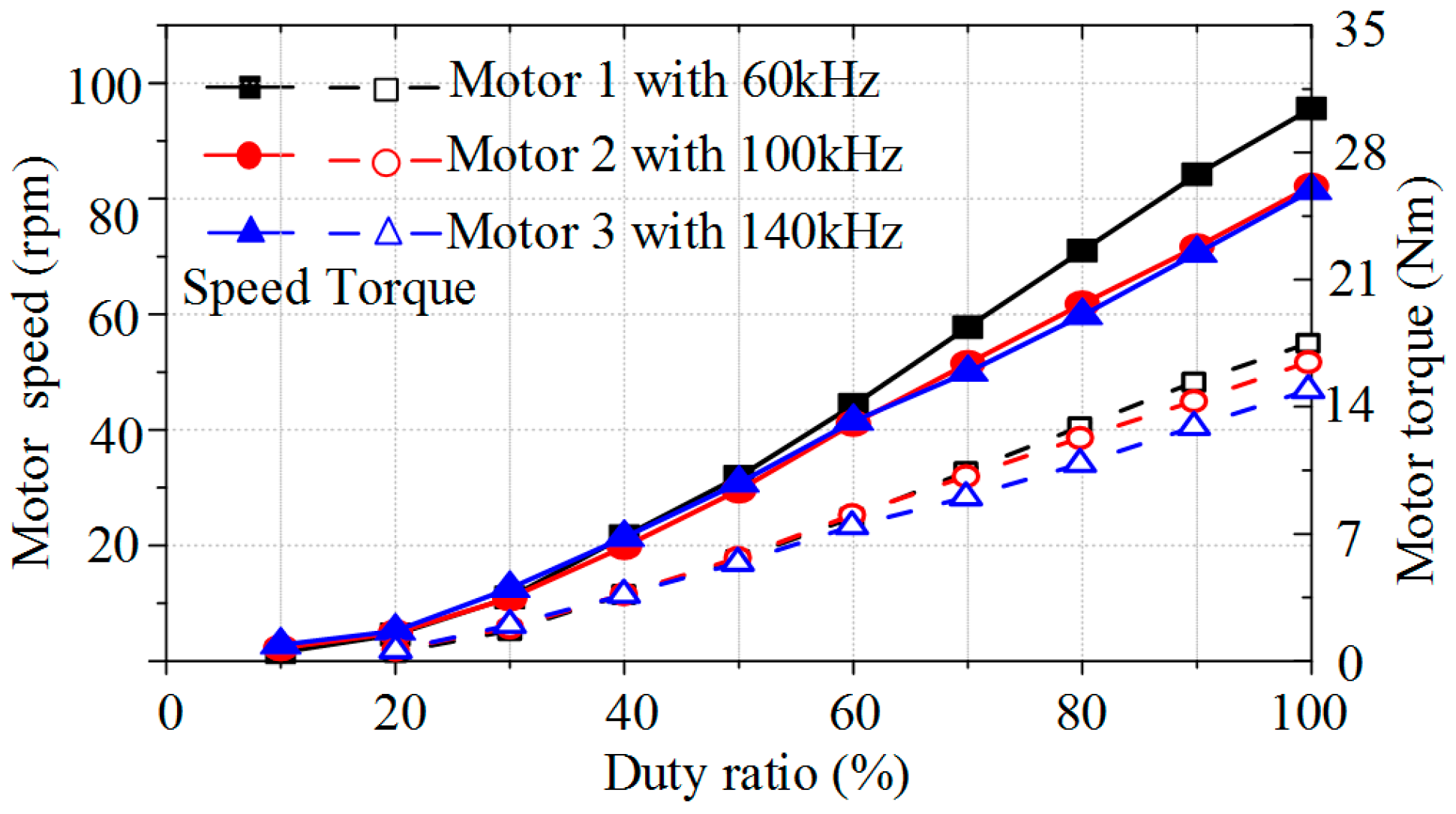
Furthermore, the speed regulation characteristics of three DC motors with respect to the variation of duty ratios are plotted as shown in Figure 12. As expected, the motor speeds can be effectively controlled while the power transmission efficiency can be maintained around the maximum values. In the experiment, the power transmission efficiency is calculated by the measured wireless output power (which is also the input power fed into the DC motor) over the measured wireless input power (which is also the output power from the power amplifier). Nevertheless, it can be observed that the measured efficiencies are somewhat lower than the theoretical values as shown in Figure 2b, especially at the range of low duty ratios. It is actually due to the system imperfection such as the additional resistance and voltage drop in the motor drive.
Finally, it can be found that the experimental results well agree with the theoretical analysis and the simulation results. It verifies that the proposed wireless DC motor drive system possesses the advantages of selectivity and controllability.
6. Conclusions
In this paper, the wireless DC motor drive system has been proposed and implemented, which can offer the unique features of selective driving and controllable speed. The keys are to utilize different resonant frequencies to selectively transfer power to different DC motors, and to employ burst fire control to perform speed control without sacrificing the power transmission efficiency. The proposed system is particularly advantageous for those applications desiring direct drive without involving power cables such as robotic manipulation in totally enclosed environment. Both finite element analysis and experimental evaluation are given to verify the validity of the proposed wireless DC motor drive system, especially the selectivity and controllability. In particular, the magnetic flux density distributions for different targeted receivers have been assessed to illustrate the concept of selectivity. According to the experimental results, under the burst fire control, the motor speeds have been effectively regulated without the sacrifice of power transmission efficiency to illustrate the concept of controllability.
Acknowledgments
This work was supported by a grant (Project No. 201511159096) from The University of Hong Kong, Hong Kong Special Administrative Region, China.
Author Contributions
Chaoqiang Jiang and K.T. Chau designed the system, analyzed the results and wrote this paper. Chunhua Liu helped perform data analysis. Wei Han helped establish the experimental platform.
Conflicts of Interest
The authors declare no conflict of interest.
References
- Covic, G.A.; Boys, J.T. Inductive power transfer. Proc. IEEE 2013, 101, 1276–1289. [Google Scholar] [CrossRef]
- Mayordomo, I.; Drager, T.; Spies, P.; Bernhard, J.; Pflaum, A. An overview of technical challenges and advances of inductive wireless power transmission. Proc. IEEE 2013, 101, 1302–1311. [Google Scholar] [CrossRef]
- Hu, P.; Ren, J.; Li, W. Frequency-splitting-free synchronous tuning of close-coupling self-oscillating wireless power transfer. Energies 2016, 9, 491. [Google Scholar] [CrossRef]
- Tan, L.; Li, J.; Chen, C.; Yan, C.; Guo, J.; Huang, X. Analysis and performance improvement of WPT systems in the environment of single non-ferromagnetic metal plates. Energies 2016, 9, 576. [Google Scholar] [CrossRef]
- Keeling, N.A.; Covic, G.A.; Boys, J.T. A unity-power-factor IPT pickup for high-power applications. IEEE Trans. Ind. Electron. 2010, 57, 744–751. [Google Scholar] [CrossRef]
- RamRakhyani, A.K.; Mirabbasi, S.; Chiao, M. Design and optimization of resonance-based efficient wireless power delivery systems for biomedical implants. IEEE Trans. Biomed. Circuits Syst. 2011, 5, 48–63. [Google Scholar] [CrossRef] [PubMed]
- Vijith Vijayakumaran, N.; Choi, J.R. An integrated chip high-voltage power receiver for wireless biomedical implants. Energies 2015, 8, 5467–5487. [Google Scholar]
- Liu, C.H.; Chau, K.T.; Zhang, Z.; Qiu, C.; Lin, F.; Ching, T.W. Multiple-receptor wireless power transfer for magnetic sensors charging on Mars via magnetic resonant coupling. J. Appl. Phys. 2015, 117. [Google Scholar] [CrossRef] [Green Version]
- Zhang, Z.; Chau, K.T.; Qiu, C.; Liu, C.H. Energy encryption for wireless power transfer. IEEE Trans. Power Electron. 2015, 30, 5237–5246. [Google Scholar] [CrossRef]
- Shekhar, A.; Prasanth, V.; Bauer, P.; Bolech, M. Economic viability study of an on-road wireless charging system with a generic driving range estimation method. Energies 2016, 9, 76. [Google Scholar] [CrossRef]
- Mi, C.C.; Buja, G.; Choi, S.Y.; Rim, C.T. Modern advances in wireless power transfer systems for roadway powered electric vehicles. IEEE Trans. Ind. Electron. 2016, 63, 6533–6545. [Google Scholar] [CrossRef]
- Wang, Z.; Wei, X.; Dai, H. Design and control of a 3 kW wireless power transfer system for electric vehicles. Energies 2016, 9, 10. [Google Scholar] [CrossRef]
- Hui, S.Y. Planar wireless charging technology for portable electronic products and Qi. Proc. IEEE 2013, 101, 1290–1301. [Google Scholar] [CrossRef] [Green Version]
- Li, X.; Meng, X.; Tsui, C.Y.; Ki, W.H. Reconfigurable resonant regulating rectifier with primary equalization for extended coupling-and loading-range in bio-implant wireless power transfer. IEEE Trans. Biomed. Circuits Syst. 2015, 9, 875–884. [Google Scholar] [CrossRef] [PubMed]
- Sun, L.; Tang, H.; Zhang, Y. Determining the frequency for load-independent output current in three-coil wireless power transfer system. Energies 2015, 8, 9719–9730. [Google Scholar] [CrossRef]
- Ahn, D.; Hong, S. Effect of coupling between multiple transmitters or multiple receivers on wireless power transfer. IEEE Trans. Ind. Electron. 2013, 60, 2602–2613. [Google Scholar] [CrossRef]
- Fu, M.; Zhang, T.; Zhu, X.; Luk, P.C.-K.; Ma, C. Compensation of cross coupling in multiple-receiver wireless power transfer systems. IEEE Trans. Ind. Inf. 2016, 12, 474–482. [Google Scholar] [CrossRef]
- Kim, Y.J.; Ha, D.; Chappell, W.J.; Irazoqui, P.P. Selective wireless power transfer for smart power distribution in a miniature-sized multiple-receiver system. IEEE Trans. Ind. Electron. 2016, 6, 1853–1862. [Google Scholar] [CrossRef]
- Hsu, J.U.W.; Hu, A.P.; Swain, A. Fuzzy logic-based directional full-range tuning control of wireless power pickups. IET Power Electron. 2012, 5, 773–781. [Google Scholar] [CrossRef]
- Zhang, Y.M.; Lu, T.; Zhao, Z.M.; He, F.B.; Chen, K.N.; Yuan, L.Q. Selective wireless power transfer to multiple loads using receivers of different resonant frequencies. IEEE Trans. Power Electron. 2015, 30, 6001–6005. [Google Scholar] [CrossRef]
- Zhang, Y.; Chen, K.; He, F.; Zhao, Z.; Lu, T.; Yuan, L. Closed-form oriented modeling and analysis of wireless power transfer system with constant-voltage source and load. IEEE Trans. Power Electron. 2016, 31, 3472–3481. [Google Scholar] [CrossRef]
Figure 1.
Wireless DC motor drive system: (a) schematic; and (b) model.

Figure 2.
Wireless power transfer (WPT) system with selectivity: (a) motor speeds resulted; (b) power transmission efficiencies; (c) burst fire control of WPT from transmitter to receiver; and (d) efficiency comparison between frequency control and burst fire control for speed control of DC motor 2.

Figure 3.
Electromagnetic field analysis at resonant frequency of 60 kHz: (a) magnetic flux line distribution; and (b) magnetic flux density distribution.
Figure 3.
Electromagnetic field analysis at resonant frequency of 60 kHz: (a) magnetic flux line distribution; and (b) magnetic flux density distribution.

Figure 4.
Electromagnetic field analysis at resonant frequency of 100 kHz: (a) magnetic flux line distribution; and (b) magnetic flux density distribution.
Figure 4.
Electromagnetic field analysis at resonant frequency of 100 kHz: (a) magnetic flux line distribution; and (b) magnetic flux density distribution.
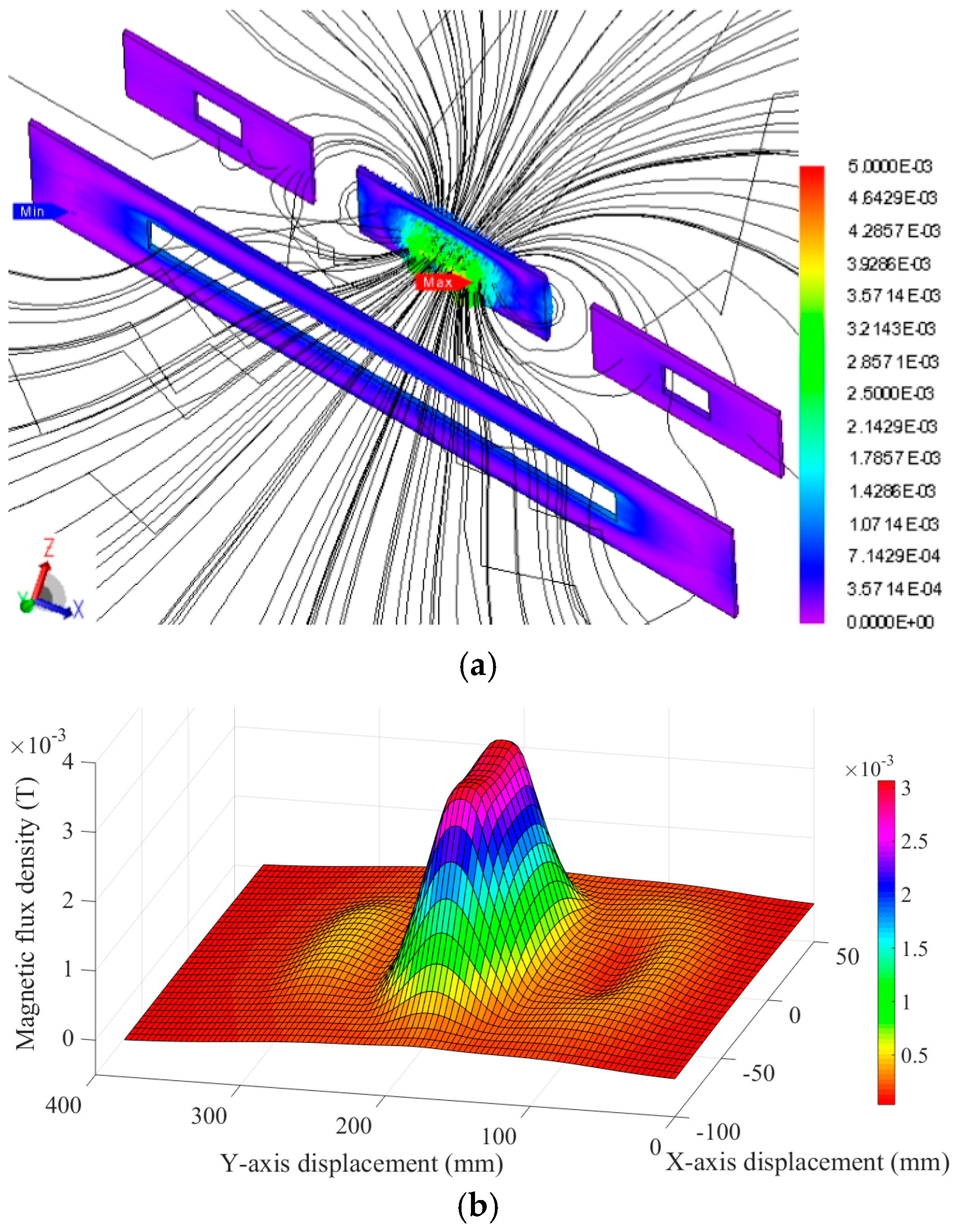
Figure 5.
Electromagnetic field analysis at resonant frequency of 140 kHz: (a) magnetic flux line distribution; and (b) magnetic flux density distribution.
Figure 5.
Electromagnetic field analysis at resonant frequency of 140 kHz: (a) magnetic flux line distribution; and (b) magnetic flux density distribution.
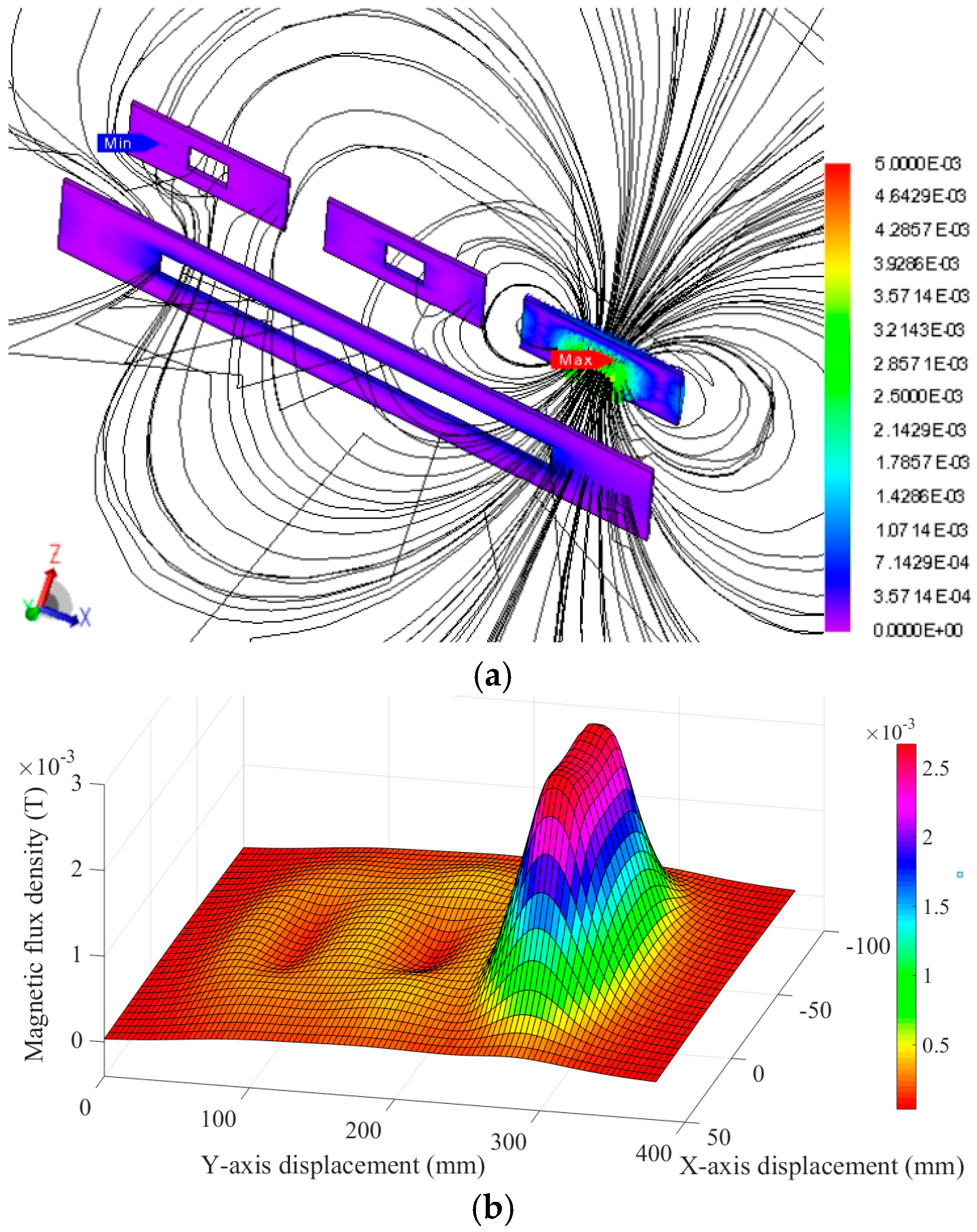
Figure 6.
Dynamic selection of DC motors: (a) transmitter current; (b) motor torque; and (c) motor speed.
Figure 6.
Dynamic selection of DC motors: (a) transmitter current; (b) motor torque; and (c) motor speed.


Figure 7.
Motor speed regulation by frequency control: (a) motor 1; (b) motor 2; and (c) motor 3.

Figure 8.
Motor speed regulation by burst fire control.

Figure 9.
Experimental setup of the proposed DC motor drive system: (a) test bed; and (b) transmitter and receiver coils.
Figure 9.
Experimental setup of the proposed DC motor drive system: (a) test bed; and (b) transmitter and receiver coils.
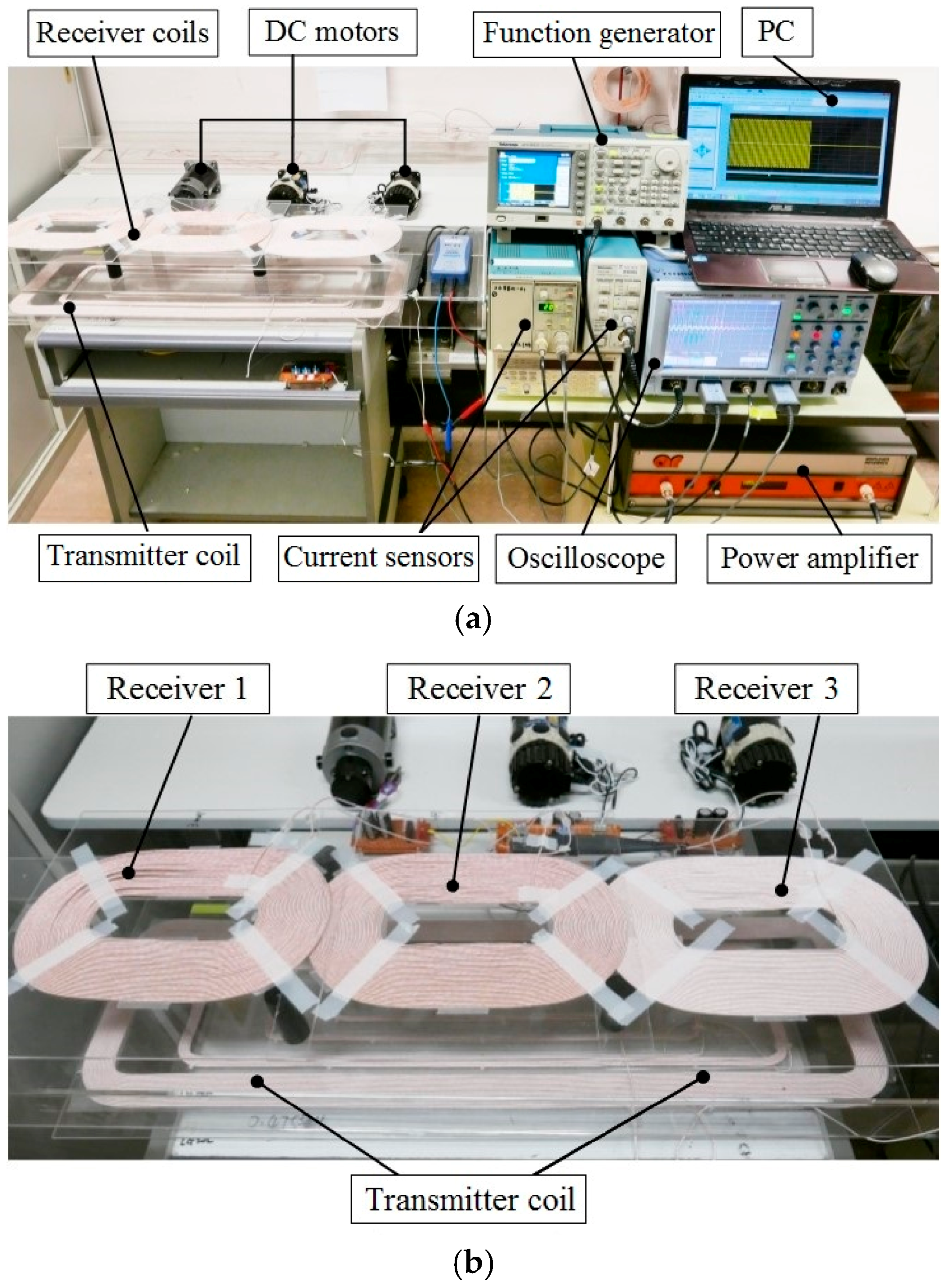
Figure 10.
Measured motor speeds at different operating frequencies: (a) motor 1; (b) motor 2; and (c) motor 3.
Figure 10.
Measured motor speeds at different operating frequencies: (a) motor 1; (b) motor 2; and (c) motor 3.

Figure 11.
Waveforms of motor 2 at duty ratio of 60%.

Figure 12.
Measured speed regulation characteristics using burst fire control: (a) motor 1; (b) motor 2; and (c) motor 3.
Figure 12.
Measured speed regulation characteristics using burst fire control: (a) motor 1; (b) motor 2; and (c) motor 3.

| Item | Value | Unit |
|---|---|---|
| Transmitter coil inductance (Lp) | 0.571 | mH |
| Receiver coil inductance (Ls1, Ls2, Ls3) | 0.253 | mH |
| Mutual inductance (M11, M12, M13) | 4.431 | μH |
| Transmitter resistance (Rp) | 1.5 | Ω |
| First receiver resonant capacitance (Cs1) | 12.323 | nF |
| Second receiver resonant capacitance (Cs2) | 4.436 | nF |
| Third receiver resonant capacitor (Cs3) | 2.263 | nF |
| Armature resistance of motor (Ra) | 1.2 | Ω |
| Receiver resistance (Rs1, Rs2, Rs3) | 0.3 | Ω |
| Supply voltage (Vs) | 60 | V |
| Electromagnetic torque (T) | 16 | Nm |
| Overall torque constant (KΦ) | 1.85 | Nm/A |
© 2017 by the authors; licensee MDPI, Basel, Switzerland. This article is an open access article distributed under the terms and conditions of the Creative Commons Attribution (CC-BY) license (http://creativecommons.org/licenses/by/4.0/).
Share and Cite
MDPI and ACS Style
Jiang, C.; Chau, K.T.; Liu, C.; Han, W. Wireless DC Motor Drives with Selectability and Controllability. Energies 2017, 10, 49. https://doi.org/10.3390/en10010049
AMA Style
Jiang C, Chau KT, Liu C, Han W. Wireless DC Motor Drives with Selectability and Controllability. Energies. 2017; 10(1):49. https://doi.org/10.3390/en10010049
Chicago/Turabian StyleJiang, Chaoqiang, K.T. Chau, Chunhua Liu, and Wei Han. 2017. "Wireless DC Motor Drives with Selectability and Controllability" Energies 10, no. 1: 49. https://doi.org/10.3390/en10010049
Note that from the first issue of 2016, this journal uses article numbers instead of page numbers. See further details here.