1. Introduction
The semi-open, recessed impeller and the enlarged side gap at the front chamber are the characteristics of vortex pumps that impel fluids with solid and fibrous material at a minimal risk of clogging. However, the efficiency of vortex pumps has remained relatively poor compared to conventional centrifugal pumps. In times of raising energy prices and strict energy goals that aim at slowing climate change, designing more efficient vortex pumps seems more desirable than ever. The aim of this paper is to find an improved design of vortex pumps in terms of efficiency and flow characteristics. To this end, an extensive literature search was conducted. Eighteen articles were identified and meta-integrated. All articles varied geometrical aspects in the impeller and/or the casing and then reported the pump characteristics. From these results, we deduce recommendations for a more efficient design. The literature search revealed that vortex pumps were designed according to two diverging design principles: the covered design or the open design. Both are based on different assumptions of the underlying operating principle of a vortex pump.
This review focuses on journal articles and conference articles that were publicly available at the time of the literature search. Eligible articles include single-parameter and/or multi-parameter experimental setups that measured how the geometry of the impeller and/or the geometry of the casing influenced the vortex pump characteristics (e.g., its head and efficiency). The results of computer-based simulations were excluded, but occasionally referred to if they contributed to a better comprehension of the material presented. From spring 2015 until autumn 2015, we searched the databases of Google Scholar (
https://scholar.google.com) for all articles containing the following keywords in the title or abstract: vortex pump, turo pump, recessed impeller, volute width, enlarged gap, side chamber gap, centrifugal pump. Because a large number of Chinese articles were found in the initial search, an additional search was conducted in spring 2015 using the database of the China Academic Journal Electronic Publishing House (
http://www.cnki.net) and the corresponding Chinese keywords. All hits were scanned with respect to their validity and content. The final sample contained 18 articles with 53 primary investigations. All of the eligible articles presented single-parameter experiments that vary only one configuration at a time while holding all other configurations constant.
Figure 1 and
Table 1 list all considered parameters in both the single-parameter and the multi-parameter experiments. Additionally,
Table 1 identifies the articles that provided the empirical base for assessing these parameters. The geometric design parameters and the operation data of the Best Efficiency Point (
BEP) were extracted from all articles. If the values were not explicitly mentioned, we estimated them from the respective graphs.
Some authors investigated the influence of a parameter on slight different configurations of a vortex pump and published it in the same article. For example, the author Wang [
4] investigated the influence of impeller width on an impeller with a diameter of 195 mm, but also tested the influence of impeller width on an impeller with a diameter of 180 mm. To distinguish between these two primary investigations of the same article for the same assessed parameter, we used the notation Wang [
4]-a for the first primary investigation and Wang [
4]-b for the second primary investigation (cp. second column of
Table 1). Similar, it applies to studies of other authors (e.g., for the impeller diameter as assessed parameter: Wang [
4]-c and Wang [
4]-d ; Ohba et al. [
9]-a and Ohba et al. [
9]-b; Lubieniecki [
11]-a, Lubieniecki [
11]-b and Lubieniecki [
11]-c). Therefore,
Table A1 of the
Appendix summarizes the geometry data of the 53 primary investigations.
Several studies were not integrated into this review because of their internal scaling (e.g., [
20,
21,
22]), missing data (e.g., [
15]), ambiguous representation of the data (e.g., parts of [
2]), non-experimental nature and/or missing validation of the simulations (e.g., [
23,
24,
25,
26,
27,
28,
29]). Some primary studies varied more than one parameter at a time when reporting the characteristics ([
1,
2,
4,
9,
11,
17] and [
8] (similar in [
30])). However, the primary studies were limited to single-parameter investigations because it is the only setup that allows isolating how distinct variations affect the
BEPs. Further, deductions can be hardly derived from the multi-parameter investigations due to missing data and missing parameter variations.
2. Design Principles of Vortex Pumps
The literature search revealed that vortex pumps were designed according to one of two design principles: the covered design or the open design.
2.1. Covered Design
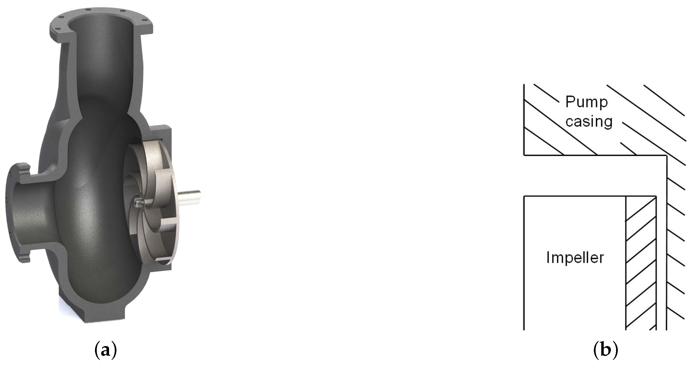
In the covered design (
Figure 2a), the impeller is set back into the casing, and the casing thus completely covers the radial impeller outlet (as
Figure 2b illustrates). Researchers who follow this design concept likely assume that the operating principle of vortex pumps is comparable to a hydraulic coupling, where the impeller induces a vortex in the enlarged side chamber and thereby transports the fluid (e.g., [
11,
29]). Given that this operating principle is at work, it seems most beneficial to cover the impeller to the casing. Doing so allows the forming of stronger vortices in the front chamber. Hence, the working transmission of the impeller would release its force to the fluid on the front side, and only small losses occur at the radial exit of the impeller. The literature search yielded that at least 32 out of 53 articles used the covered design, while the exact design was unspecified in 13 articles.
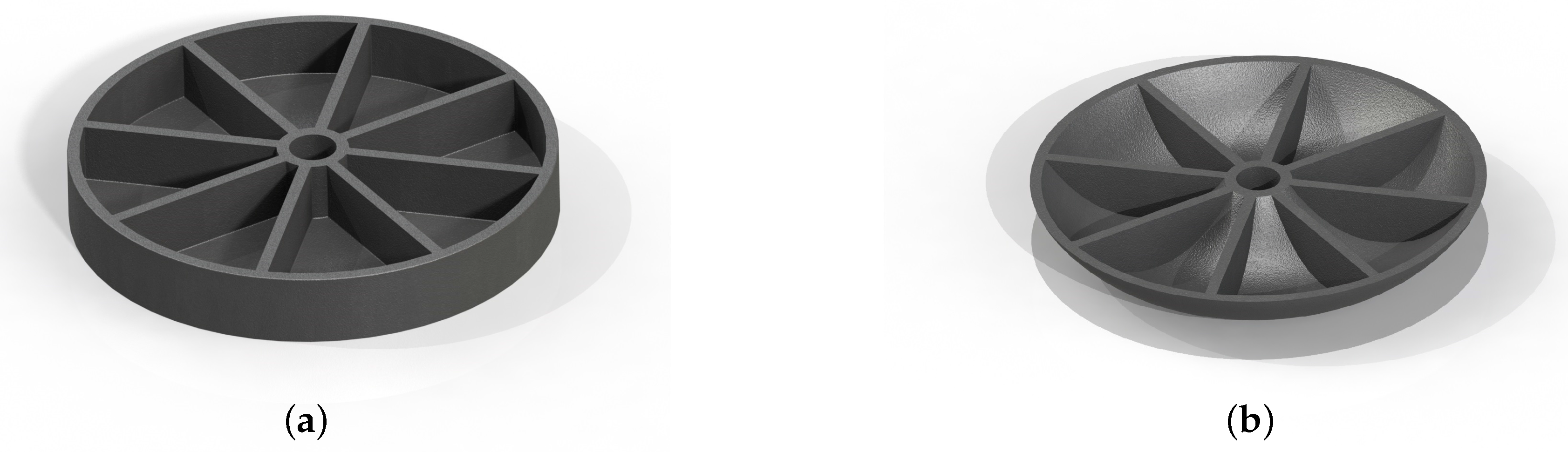
The covered design is sometimes associated with pan impellers whose shape is either rectangular (
Figure 3a) or round (
Figure 3b). Both impellers were likely designed with the intent to optimize the vortex formation. The geometric closing of both impellers’ radial outlet creates an axial energy transfer to the side chamber. In this case, the round shape (
Figure 3b) seems the more suitable form because the round shape guarantees a better guidance of the fluid flow. Overall, it is noteworthy that a pan impeller is not a necessity for the covered designs, although eight out of the 32 investigations on covered designs used them ([
9,
10]).
Various authors developed fluid transport models for the covered designs and pan impellers. For example, Schivley and Dussourd [
20], Aoki ([
31,
32]) and Ohba and colleagues ([
9,
22,
33]) developed predicting methods for the performance and design methods for vortex pump impellers.
2.2. Open Design
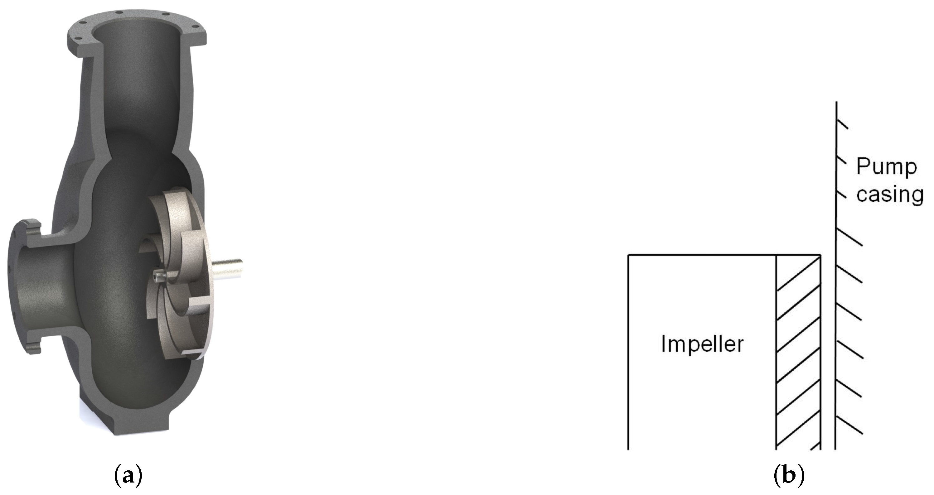
An alternative design principle of vortex pumps is the open design. Here, the casing does not cover the impeller. Instead, the vortex pump looks similar to a centrifugal pump with a semi-open impeller and wide front gap (
Figure 4a,b). The assumed operating principle is that of a conventional centrifugal pump: fluids are transported through the impeller itself and without the assistance of a vortex. Due to the wide front gap, however, exchange losses occur. These losses would explain the relatively low efficiency and the relatively low head of vortex pumps compared to conventional centrifugal pumps (e.g., [
1]). Given that the working principles of vortex pumps and conventional pumps are similar, it follows that comparable design recommendations apply to vortex pumps as they do to conventional centrifugal pumps. For example, an impeller overlapping with the casing would disrupt the outflow from the impeller and, hence, increase losses.
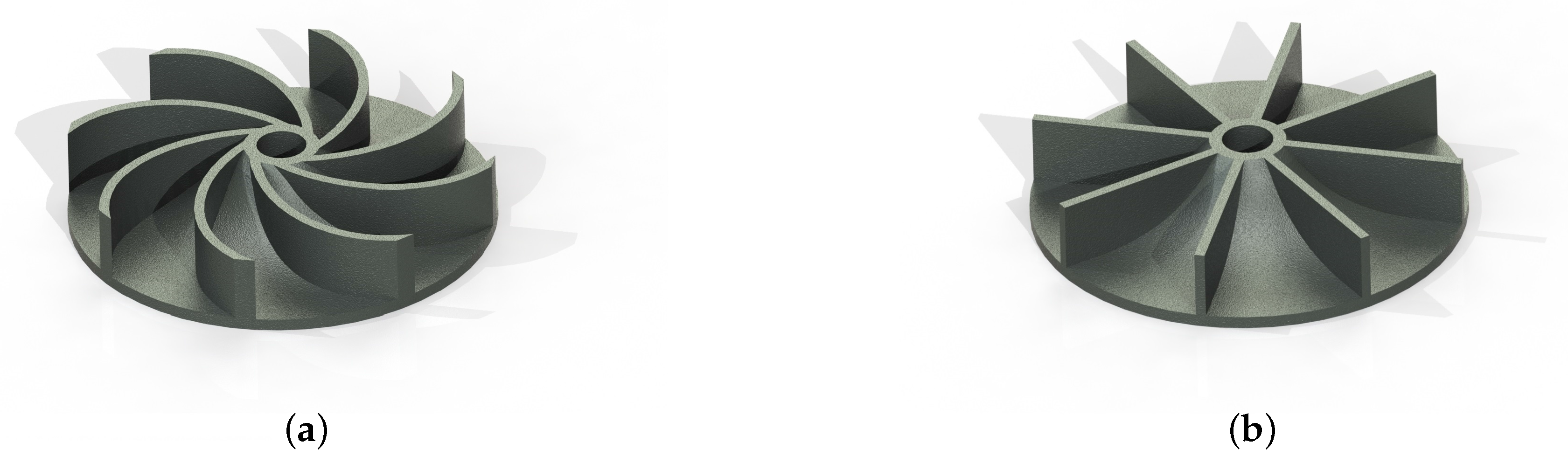
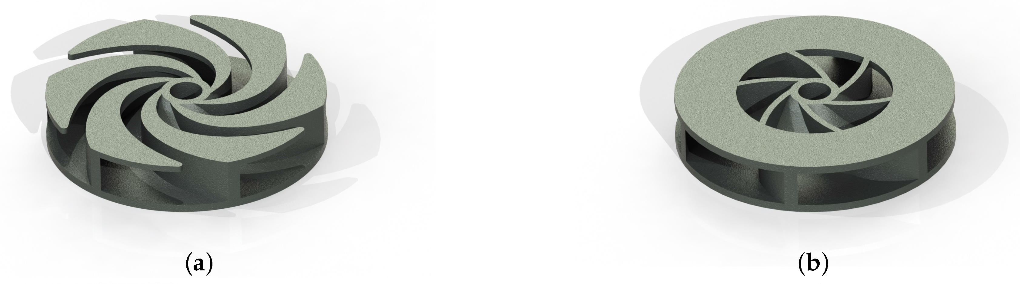
In the open design, the impeller frequently resembles a semi-open impeller, similar to that of a conventional centrifugal pump. The blades are curved or straight and, in both cases, pulled up to the hub (
Figure 5a,b). This design can be modified when winglets are added to the front edges of the blades.
Figure 6a is an example of an impeller with winglets. The maximal execution on winglets results in a front shroud (
Figure 6b).
2.3. Interim Conclusion
Overall, the covered design and the open design are based on different assumptions about the underlying operating principle of a vortex pump. Because it is unclear which of the two operating principles is mainly responsible for the fluid transport, it is unknown which of the two design types should be prioritized in the first place (in terms of higher head and greater efficiencies). As a consequence, it is unclear which geometric modifications ultimately optimize vortex pumps.
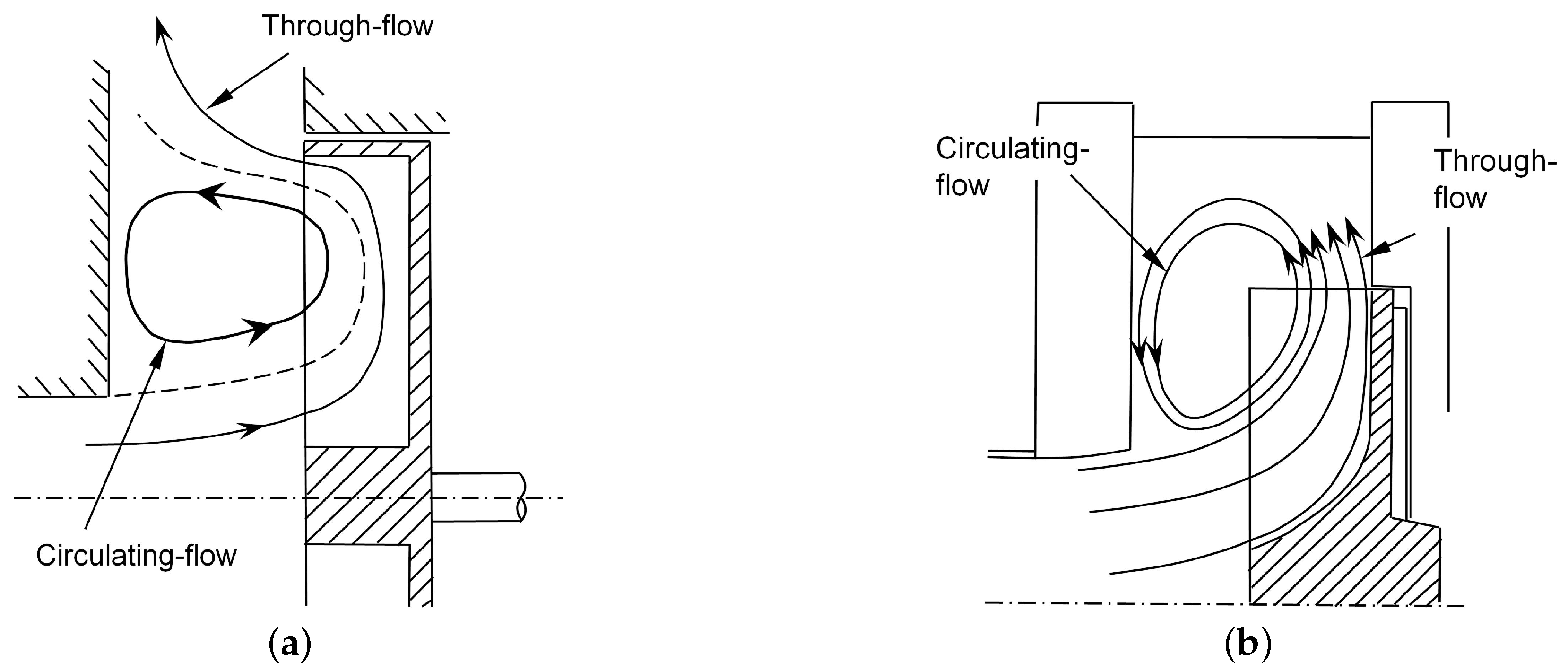
Regardless of the operating principles at work, the fluid flow in the front chamber can be principally divided into two components: a through-flow and a recirculating flow.
Figure 7a,b illustrates the two flows on behalf of the covered design (
Figure 7a) and the open design (
Figure 7b), respectively. It is an open question to what degree each component contributes to the fluid transport and to what degree the two components can be separated.
3. Results
3.1. Presentation of Data
For the presentation of the data, we used the values head (
H) or correspondingly the dimensionless value pressure coefficient (
ψ) and the efficiency (
η). The pressure coefficient is a dimensionless quantity that can be derived from the model laws and serves to characterize the operating behavior of a pump. It describes the head of a pump. The pressure coefficient is defined as:
with the gravitational acceleration
g, the head
H, the rotation speed
n and the impeller diameter D
2.
The efficiency is a ratio to characterize the quality of a machine. It sets the effective power in relation to the consumed power. For pumps, different efficiencies can be named, as for example the hydraulic efficiency or the aggregate efficiency, depending on which power serves as effective power or consumed power. In this study, we did not distinguish between authors using hydraulic efficiencies or aggregate efficiency, as none of the considered articles provided any information, and it was sufficient to determine trends.
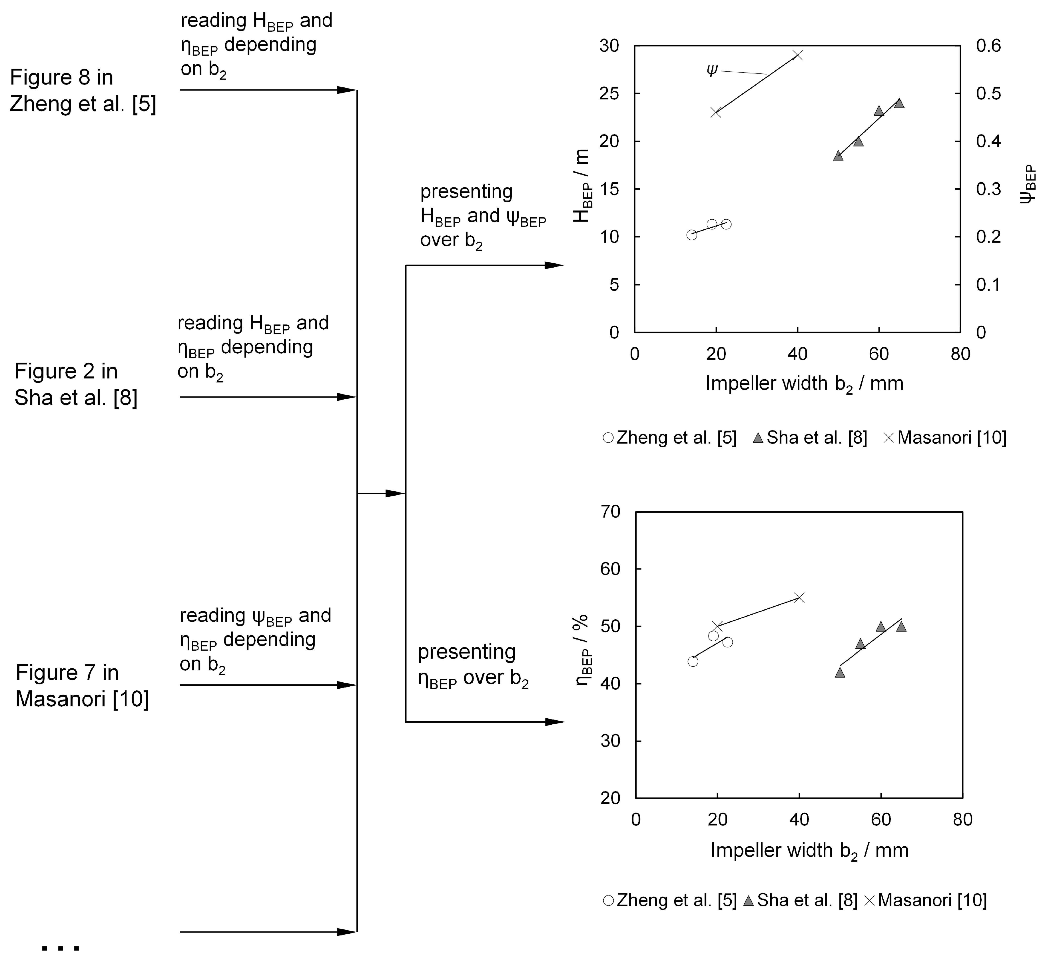
Figure 8 illustrates how the head curves, pressure coefficient curves and the efficiency curves from the primary studies were generated (on the left). The example shows how variations in the impeller width affected the head (
H) and the pressure coefficient (
ψ; both at the top right panel) and efficiency (
η; at the bottom right panel). When integrating primary studies, first the highest efficiency for each impeller width was read off and thereby defining its operation point for best efficiency (
BEP). All
BEPs were combined into a single graph by plotting them against their respective impeller width. Finally, a linear trend line was fitted through all
BEPs of each primary study. These steps were repeated for all primary studies. This representation allows displaying multiple studies in a single graph at the cost of reducing the analyses to comparing
BEP values.
To distinguish between the
BEPs from different design principles of vortex pumps (e.g., covered design, open design), the following coding scheme is used for all symbol markers in the figures: grey- or black-filled markers represent covered designs of vortex pumps with semi-open impellers (e.g., [
8] in
Figure 8); cross markers represent covered designs of vortex pumps with pan impellers, either square-shaped or round-shaped impellers (e.g., [
10] in
Figure 8); black/white two-faced markers represent the open designs of vortex pumps; non-filled markers represent non-specified designs with unknown impeller types (e.g., [
5] in
Figure 8).
3.2. Single-Parameter Investigations
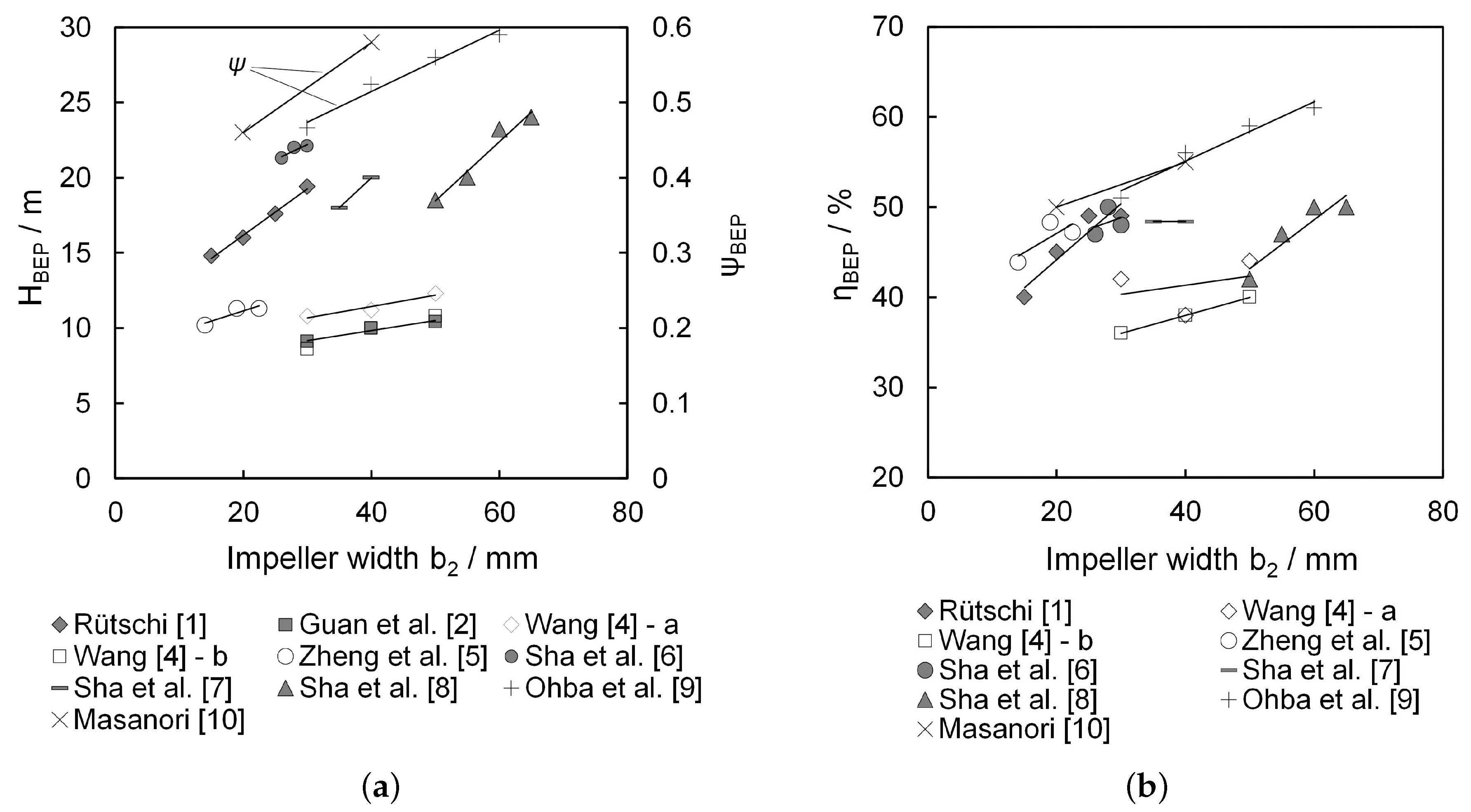
3.2.1. Impeller Width
The impeller width refers to the depth of the blades.
Figure 9a pictures the head and the pressure coefficient over the impeller width.
Figure 9b shows the efficiency at the
BEP for each vortex pumps. Generally speaking, the results suggest that a larger impeller width leads to greater head and higher pressure coefficients. The relation between the impeller width and efficiency is not as clear. Whereas the majority of the studies suggest the efficiency increases with the impeller width increasing, some studies [
5,
6] suggest a threshold for this trend after which the efficiency drops.
Figure 9a,b shows that the gradients of trend lines differ between the studies. This suggests the presence of the confounding influences of other design parameters. The studies differed in their vortex pump design principle, but also in their specific design, for example the casing design, the volute width, blade number, etc. That might influence the maximum reached head and efficiency, as well, and leads to different trends and absolute values between the studies.
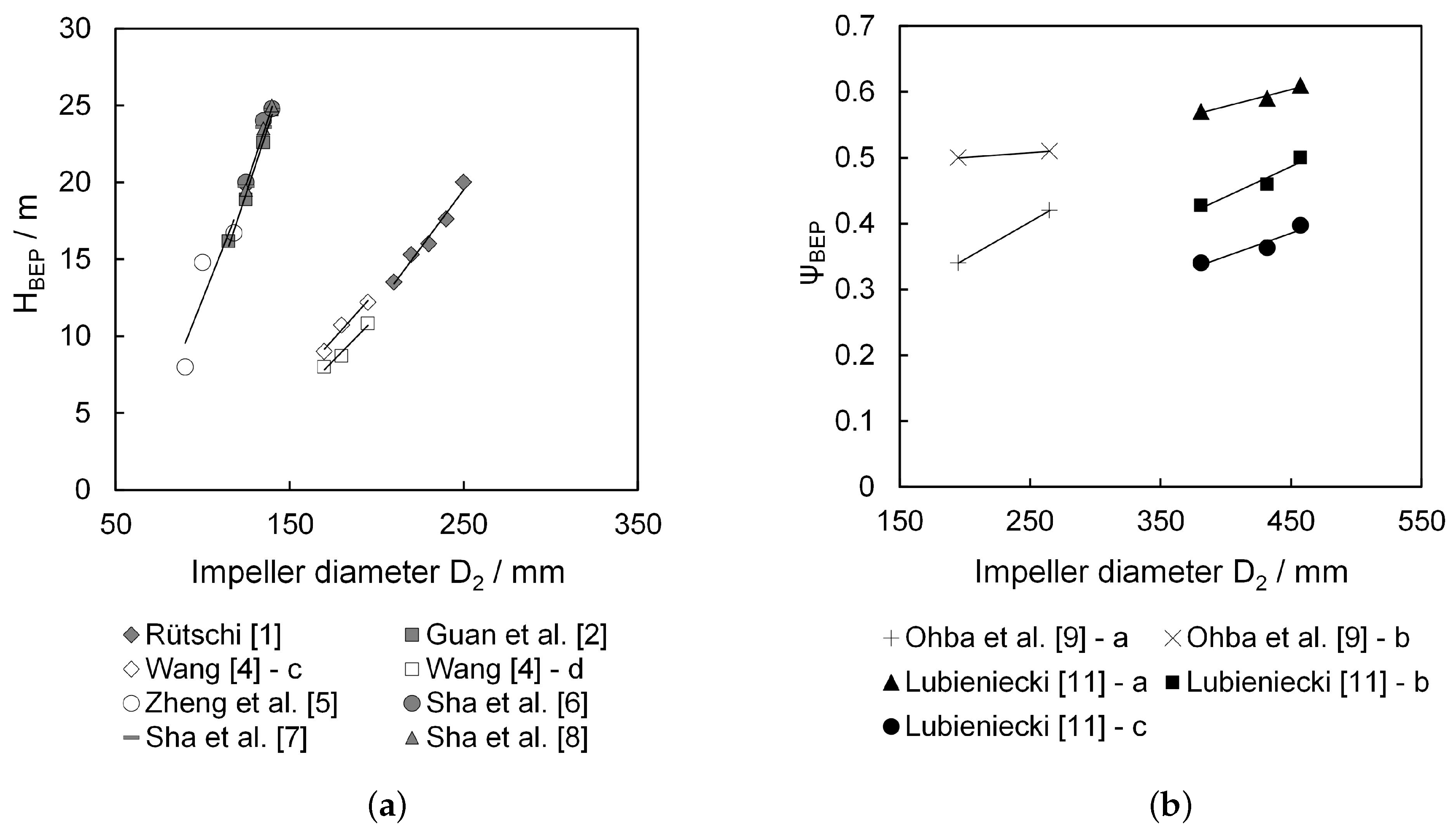
3.2.2. Impeller Diameter
The majority of the primary studies assessed the effect of varying the impeller diameter. Overall, these studies univocally conclude that increasing the impeller diameter yields greater head and pressure coefficients. This is in accordance with insights from common centrifugal pumps where similar effects are known (e.g., [
35,
36]).
Figure 10a plots the head for the
BEP against the impeller diameter.
Figure 10b plots the pressure coefficient for the
BEP against the impeller diameter. Notably, the gradients between the studies differ substantially, suggesting the presence of confounding influences on the head characteristics. Here again, the studies differed in their specific design of tested vortex pump, leading probably to different trends and absolute values between the studies.
Figure 11 combines the studies of
Figure 10a,b and plots the efficiency for the
BEP over the impeller diameter. Overall, the trends suggest that greater impeller diameters lead to greater efficiency. However, this trend is not necessarily linear. The studies of Guan et al. [
2], Zheng et al. [
5] and Sha et al. [
8] for example suggest a U-shaped relationship.
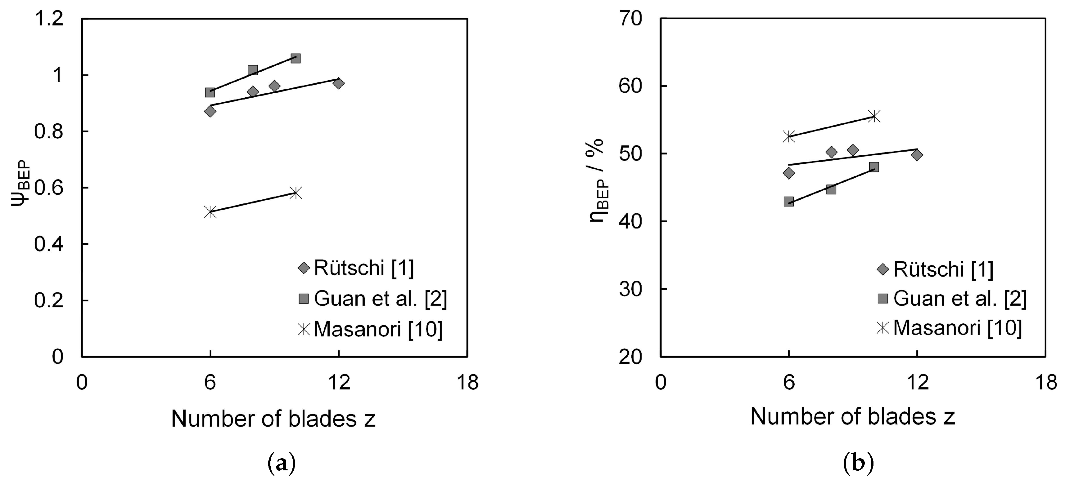
3.2.3. Number of Blades
All studies suggest that an increased blade number leads to greater pressure coefficients and greater efficiency.
Figure 12a shows the influence of the number of blades on the pressure coefficient for the
BEP.
Figure 12b plots blade numbers against efficiency. Noteworthy, Rütschi [
1] reported a decreasing efficiency for 12 blades. In combination with the other studies, this suggests that more than 10 blades are not beneficial.
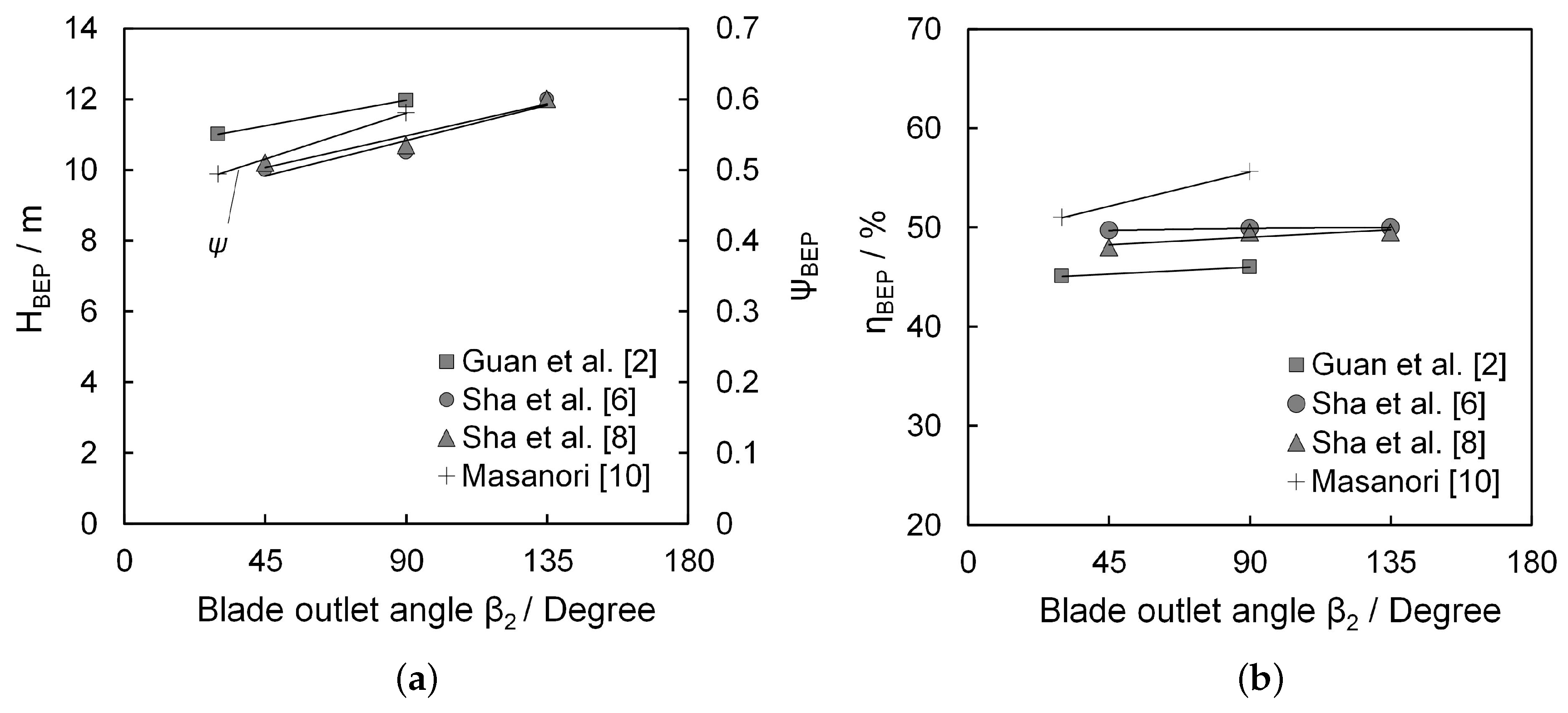
3.3. Blade Angles
The influence of the blade angle was studied in two ways: either by changing the blade outlet angle
β2 at a constant blade inlet angle
β1 or, vice versa, by changing the blade inlet angle
β1 at a constant outlet angle
β2. Overall, increasing the outlet angle seems to increase the head and the pressure coefficient. Greater angles thus lead to more efficiency. In contrast, the transition from straight blades to forward curved blades is marginal.
Figure 13a summarizes the influence of the blade outlet angle
β2 on the pressure coefficient. The results suggest that increasing the blade outlet angle improves the pressure coefficient. In particular, it is demonstrated that an impeller with an outlet angle greater than 90° (i.e., forward curved blades) is associated with greater pressure coefficients.
Figure 13b plots the influence of the blade outlet angle
β2 against efficiency. This shows the tendency of increasing efficiency with increasing blade angle.
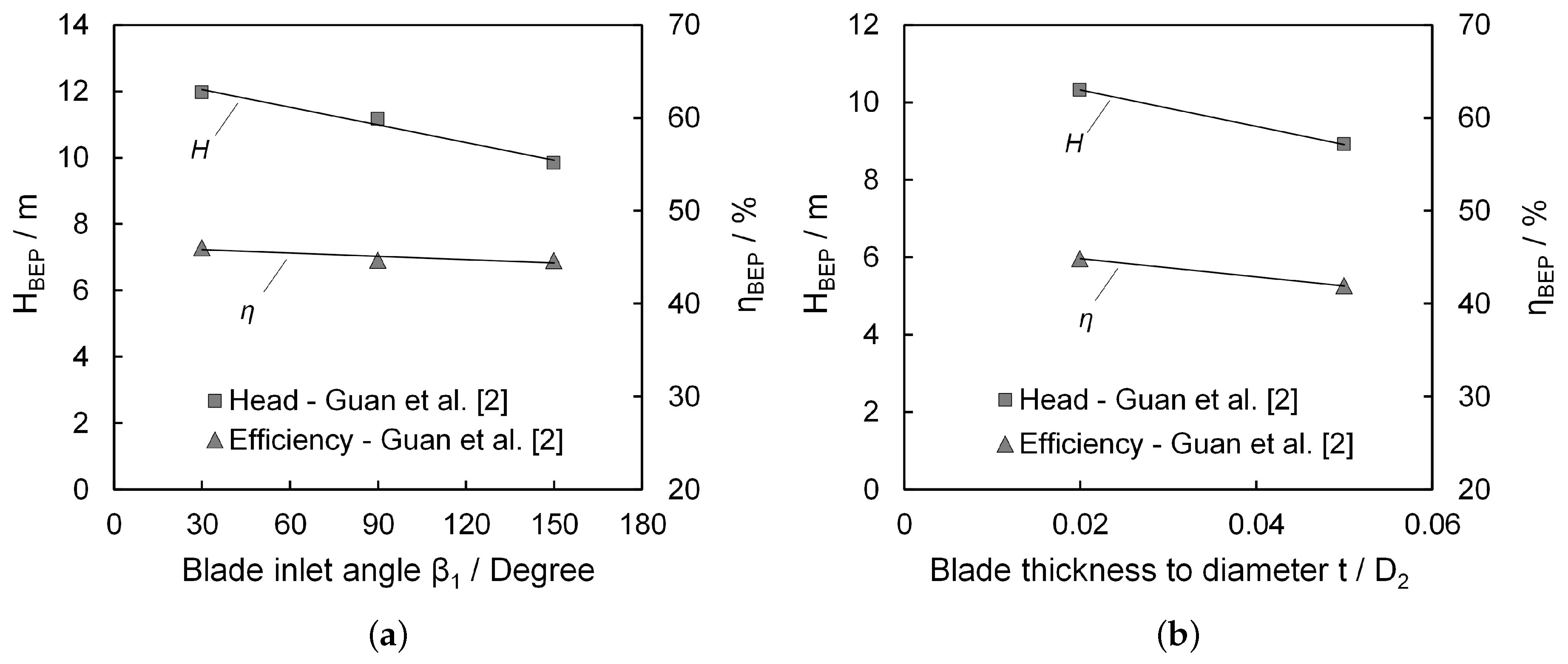
Guan et al. [
2] examined the influence of varying the blade inlet angle
β1.
Figure 14a shows the results for head and efficiency that suggest increasing the inlet angle decreases the head and slightly the efficiency.
3.4. Blade Thickness
Only a single study examined the influence of varying the blade thickness [
2].
Figure 14b suggests that the head and the efficiency of the
BEP drop with blade thickness increasing. However, only two configurations were tested.
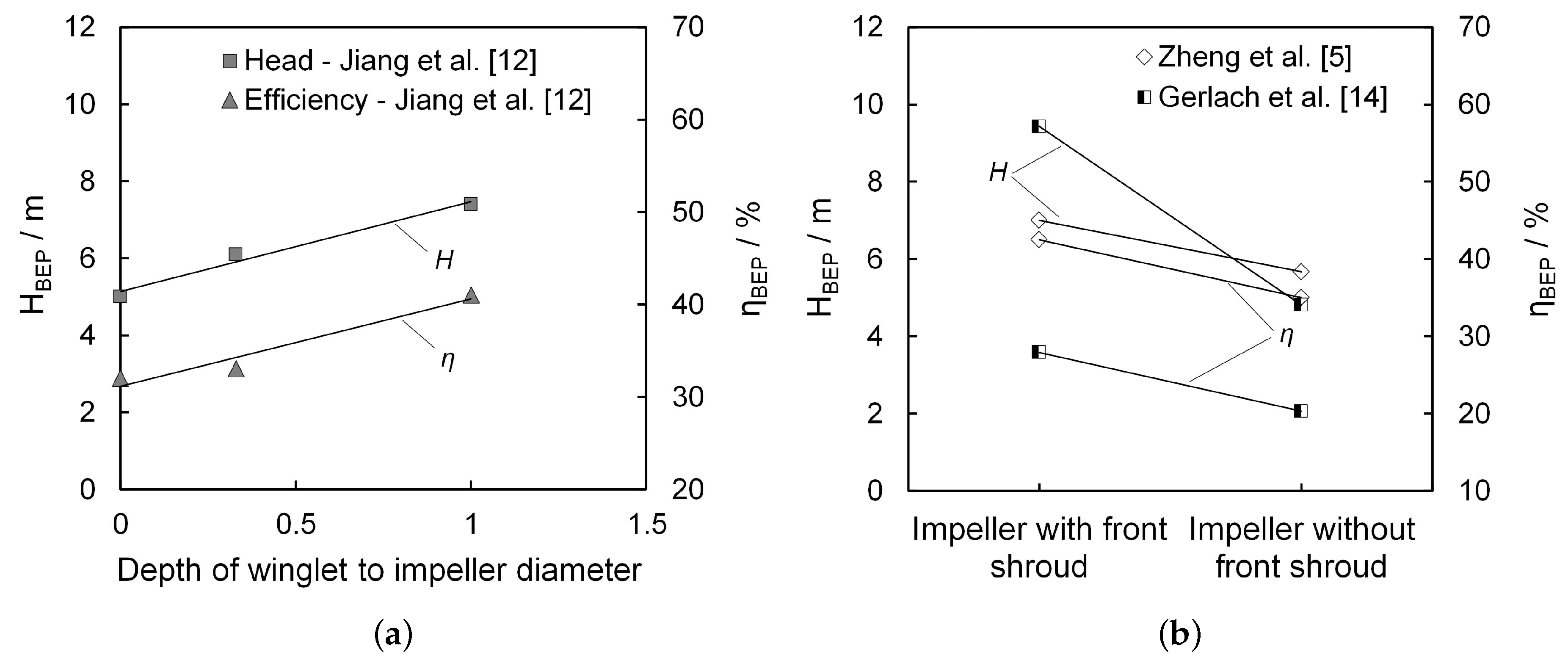
3.5. Winglets and Front Shrouds
Jiang et al. [
12] examined the impact of adding winglets to a semi-open impeller. The study compared two different winglet depths to an impeller without winglets.
Figure 15a shows the results for head and efficiency over the ratio of winglet depth to impeller diameter. Overall, the head and the efficiency of the impellers with winglets were lower than those of the impeller without winglets. Decreasing the ratio of winglet depth to impeller diameter was associated with a lower head and lower efficiency. Notably, another study by Gerlach et al. [
14] demonstrated that adding winglets to a vortex pump with free outflow from the impeller (i.e., without coverage) and four curved blades led to a greater head and more efficiency. On a further note, Cervinka [
24] investigated the operation of winglets using a numerical model. The author compared an impeller with winglets with a geometrically similar impeller without winglets. The study concluded that an impeller with winglets deteriorates the pump characteristic and its efficiency. These results have not been experimentally validated however, and they contradict the measurement results of Jian et al. [
12] and Gerlach et al. [
14].
The maximal design of winglets results in a front shroud. Adding a front shroud strongly limits the use of vortex pumps (e.g., for pumping solid-containing fluids); however, such a modification can prove insightful for understanding the principle characteristics of a vortex pump.
Figure 15b shows the results for an impeller without a front shroud compared to an impeller with a front shroud. Adding the front shroud was associated with a greater head and more efficiency compared to the semi-open impeller.
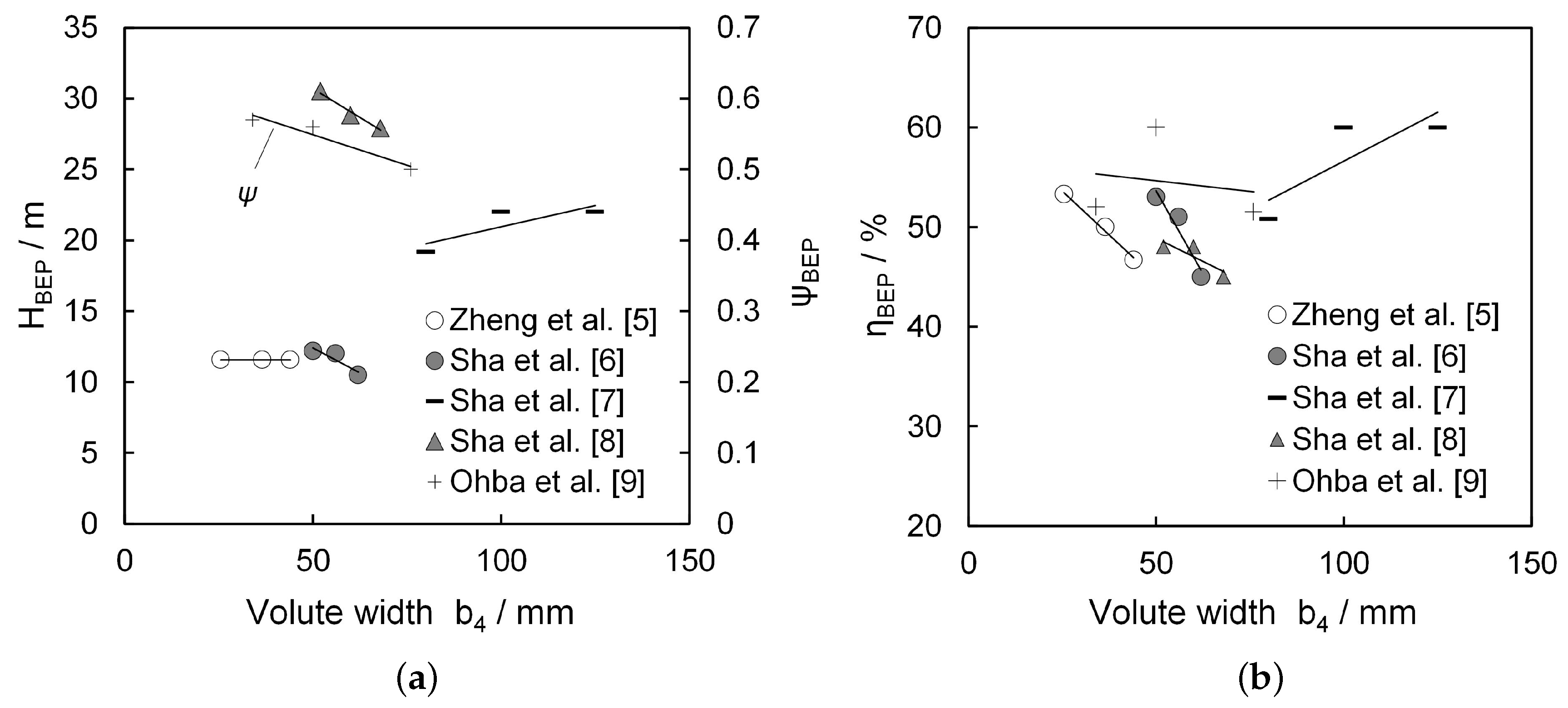
3.6. Volute Width
The volute width refers to the width of side chamber gap between the casing and the impeller.
Figure 16a shows the head and pressure coefficient over the variation of volute width. All, but one study (Sha et al. [
7]), suggested that the head and pressure coefficient decrease when the volute width increases.
Figure 16b plots the associated efficiencies. Again, all but one study (Sha et al. [
7]) suggested that the efficiency decreases when volute width increases. Each study seems to have its own optimal efficiency point depending on the volute width. A parabolic curve seems to fit the measurement points better than a linear trend line.
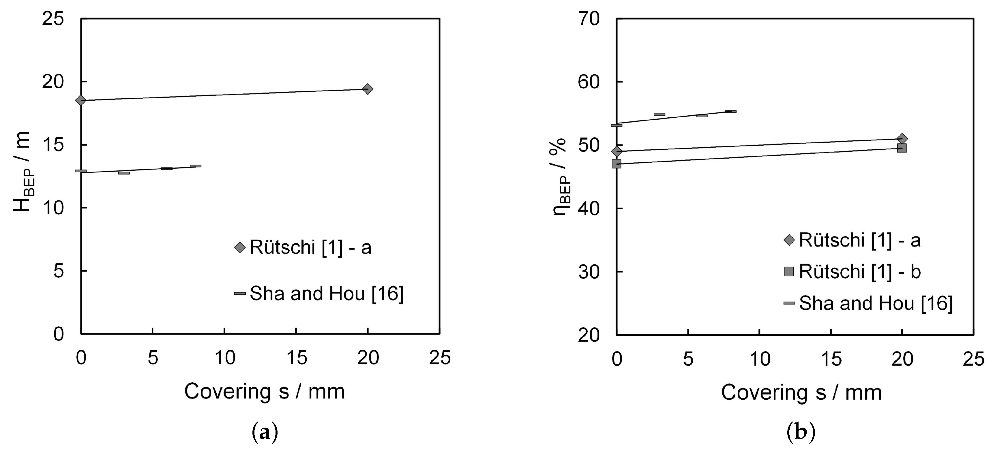
3.7. Covering of the Impeller
The covering of the impeller refers to the overlap between the impellers’ radial outlet and the casing.
Figure 17a depicts how decreasing the covering affects the head for the
BEP. At zero, the impeller completely covers the casing. With increasing values, the covering decreases until the impeller is completely uncovered (the maximum value for each study; e.g., 20 mm in Rütschi [
1]).
Figure 17a suggests that covering the impeller decreases the head.
Figure 17b shows the associated efficiencies for the covering of the impeller. This suggests that covering the impeller decreases efficiency.
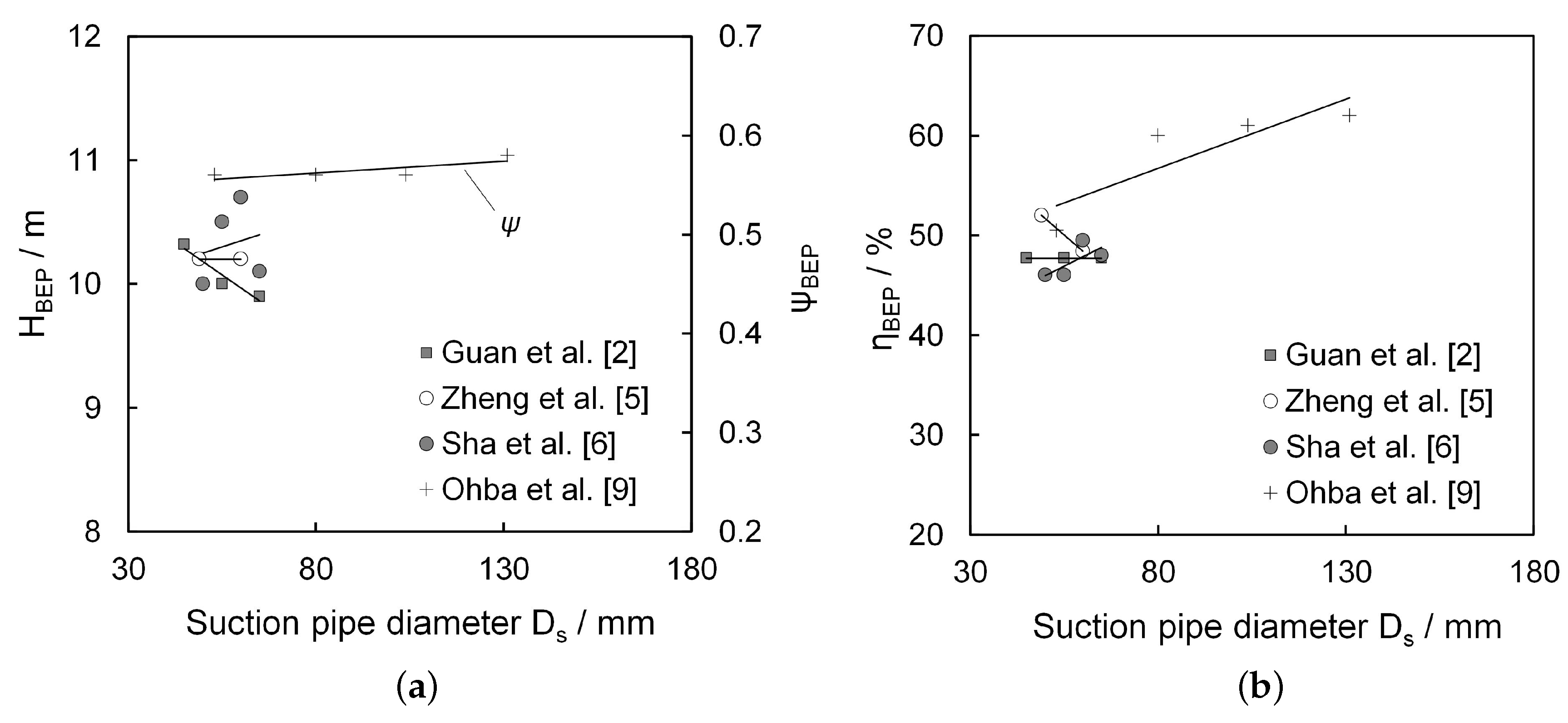
3.8. Suction Pipe Diameter
The suction pipe diameter refers to the pipe diameter at the suction entrance of the pump. Variations in the suction pipe diameter only marginally affect the head and the pressure coefficient. The effect of the suction pipe diameter on efficiency is contradictory. The studies of Sha et al. [
6] and Ohba et al. [
9] show an increase of efficiency with increasing suction pipe diameter, while the study of Zheng et al. [
5] shows the opposite behavior. Only Guan et al. [
2] shows no influence of suction pipe diameter on the efficiency.
Figure 18a shows the results for the head and the pressure coefficient over the suction pipe diameter.
Figure 18b shows the respective values for efficiency.
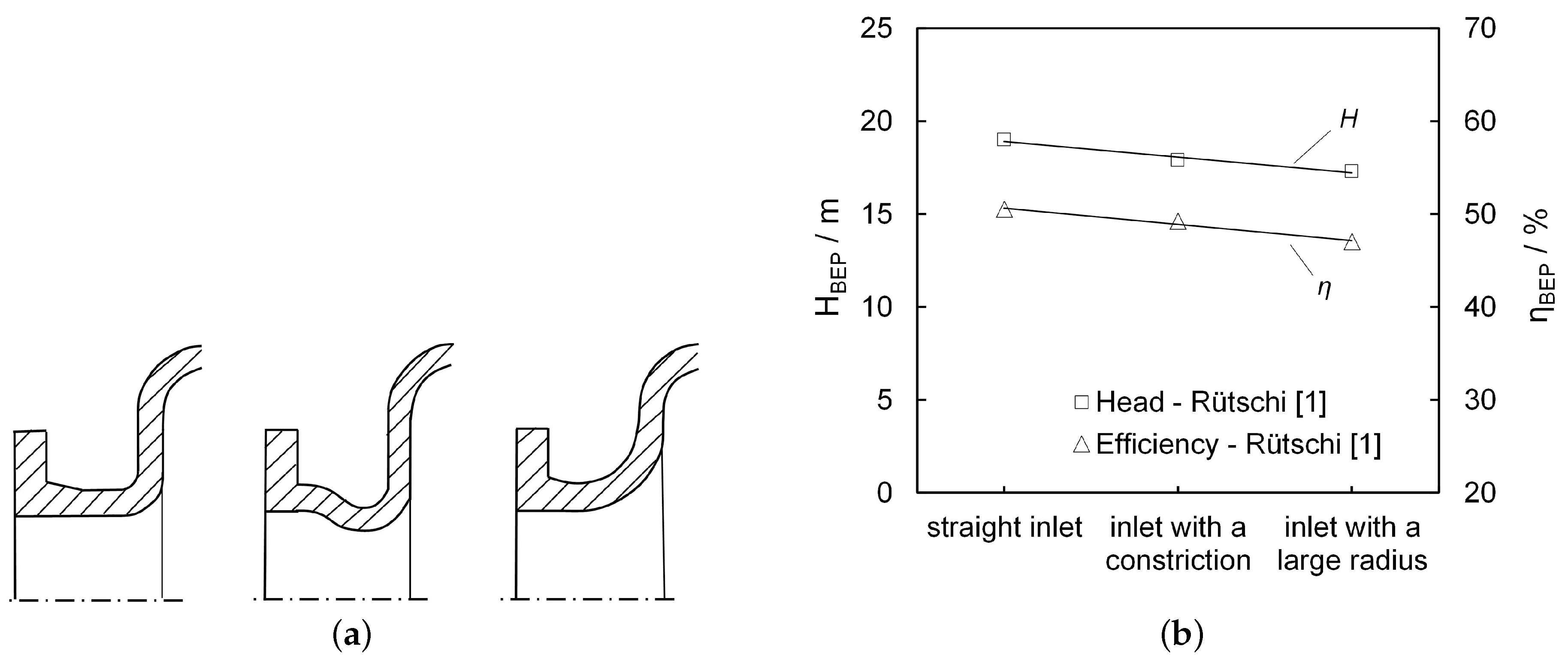
3.9. Suction Pipe Inlet Geometry
Only Rütschi [
1] examined the suction pipe inlet geometry, i.e., the design of inlet from the suction pipe of the pump to the casing. Three variations were considered, shown in
Figure 19a (from left to right): a straight inlet, an inlet with a constriction and an inlet with a large radius of curvature.
Figure 19b plots the results of the measurements against the head and efficiency. A straight inlet of the suction pipe seems preferable in terms of highest head and efficiency. The comparisons were based on an impeller with nine straight blades.
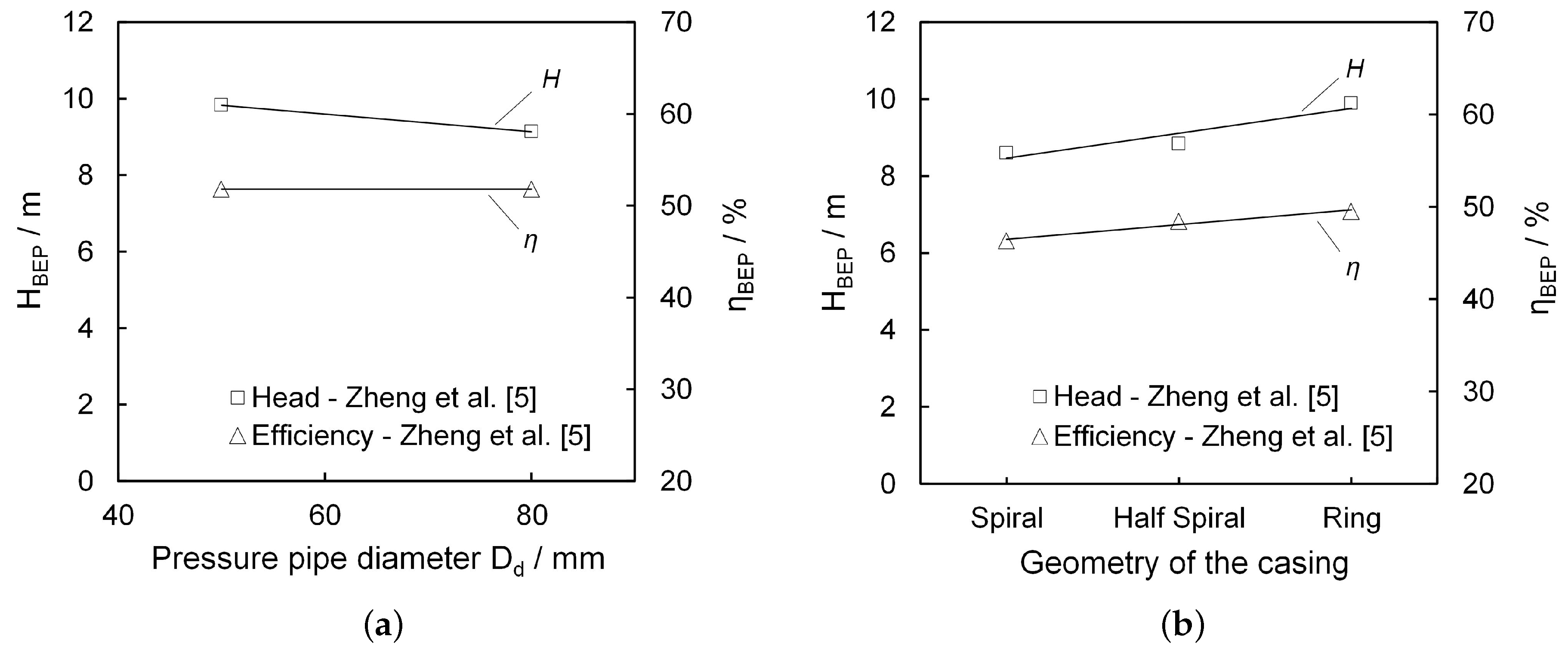
3.10. Pressure Pipe Diameter
A single study tested variations in the pressure pipe diameter by two configurations (Zheng et al. [
5]).
Figure 20a shows the associated head and efficiency. The results suggest that a large pressure pipe diameter decreases the head. The impact on the efficiency is insignificant. However, it has to be considered that only two configurations were tested, and correlations are hard to deduce.
3.11. Geometry of the Casing
The geometry of the casing refers to the specific design of the casing, for example the comparison between a spiral casing or a ring casing.
Figure 20b shows how the geometry of the casing influences the head and efficiency. The graph is based on the study of Zheng et al. [
5]. The study compared a spiral casing with a ring casing and with a half spiral casing. Both head and efficiency were highest when the ring casing was used.
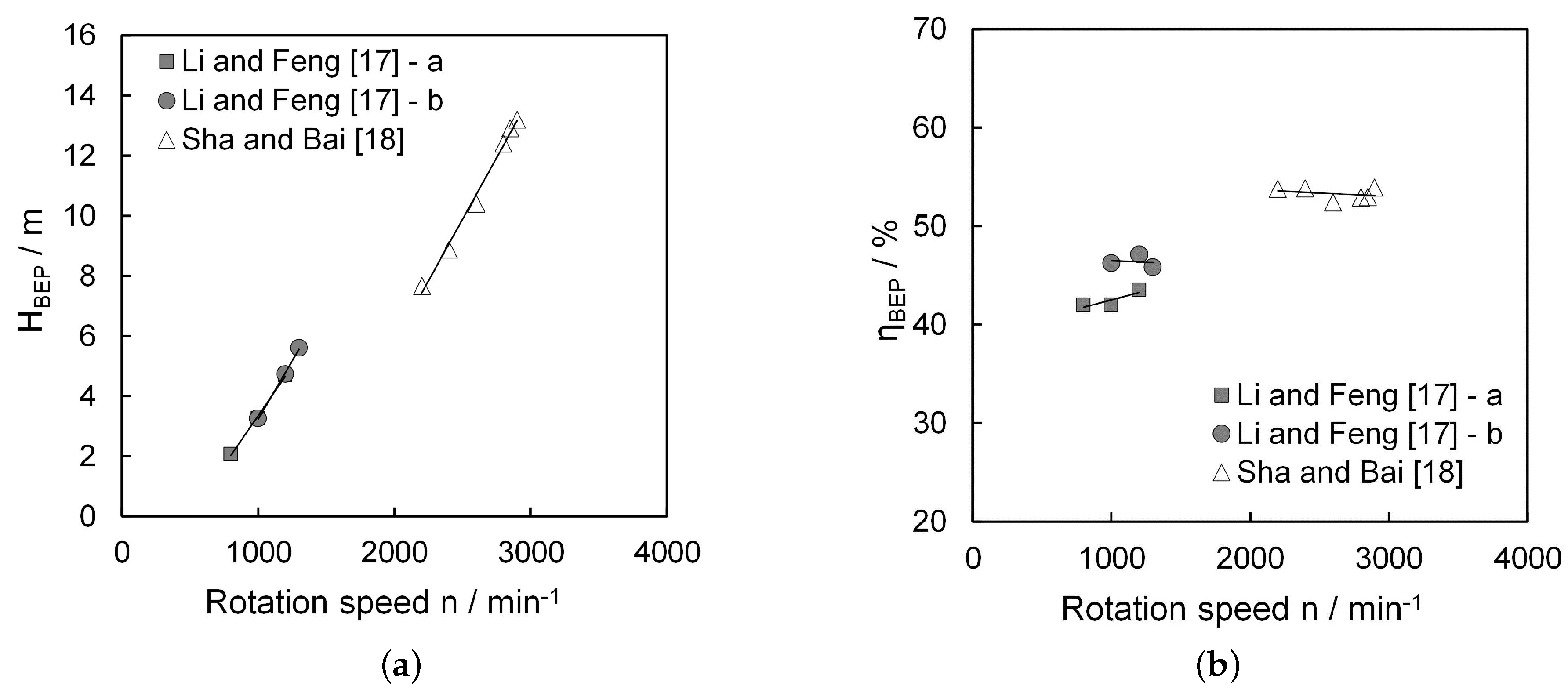
3.12. Rotation Speed
As depicted in
Figure 21a, three studies univocally suggest that higher rotation speeds lead to greater head. In contrast,
Figure 21b suggests that rotation speed has little effect on efficiency. The effect on head resembles insights on common centrifugal pumps for which similar effects have been observed (e.g., [
35,
36]).
3.13. Correlations between Parameters
Some of the single primary studies explicitly deduce recommendations about specific ratios for geometric parameters with the goal of maximizing head and/or achieving the highest efficiencies.
Table 2 provides an overview on the recommended ratios. We tried to verify the suggested correlations based on all collected primary studies. For this propose, all studies were considered that indicated both parameters while testing one of them. For example, the relation between suction pipe diameter and impeller diameter, mentioned as 0.45 by Ohba et al. [
22] (
Table 2, last column), was tested by looking at all single primary studies that changed the suction pipe diameter with constant impeller diameter and vice versa. These studies were plotted over the ratio of suction pipe diameter to impeller diameter to identify optima. However, we failed to verify the suggested correlations. This was either because no studies tested the targeted correlations or the optimum itself did not exist.
4. Discussion
As a major difference in the studies, the design type was highlighted, as explained at the beginning of this paper. This is to say, in some studies, a covered design was used, a pan impeller or less common a free flow impeller. However, it is assumed that this has a significant effect on the performance, since it possibly prevents the free flow out of the impeller. A study that compares the pan impeller with covering to a normal impeller with free outflow and without covering was partly shown by Rütschi [
1]. These tested impellers are not directly comparable due to many different parameters, so that a conclusion could not be drawn. However, testing such impellers, similar in parameters, but different by the type, would be the best way to face the assumed operating principles.
Some authors describe the optimal ratios of geometric parameters to each other to achieve the highest head and efficiencies. The described optima were considered on the basis of the collected data and could not be confirmed. However, it is important to note that the slopes of the suggested trends may considerably differ between the primary studies. These differences suggest that confounding, but unobserved factors exist that moderate the relations between the geometric variation and the observed behaviors. This suggests that trends for this type of pump might be described; however, a number of unknown factors exist, so definite and formula-based relationships are not yet grasped.
Despite the fact that volute width has been assessed in a number of studies, it often remains unclear how these measurements were exactly implemented. The volute width could be varied, for example, by varying the impeller widths or by moving the impeller in the casing, to change the distance between impeller and casing. Hence, the results should be interpreted with care. The same applies for the parameter covering. Here again, it is unclear how these experiments were implemented in detail and if a change in volute width took place. Therefore, the impact on the pump-specific performance is not entirely clear for this parameter, either.
Based on the data collected, it would be interesting to calculate characteristic values, such as the specific speed or the specific diameter. This might also possibly further hint at the operating principle of the pump. However, this was not possible because many of the studies did not fully publish the geometry data and/or operating data or scaled them internally. Thus, no comparability was possible. The fact to be scrutinized is that in some cases, the same measurements were found in various publications.
Overall, it is surprising that no literature works were found for the clogging behavior. Therefore, the results on the influence of the parameters always relate purely to the hydraulic data of the delivery and do not indicate the clogging behavior. This opens up a large field of research since vortex pumps are actually used for the transport of fluids with solids. The same applies for the usage of back vanes on vortex pumps. It is the practice of pump suppliers to use back vanes on vortex pump impellers, but no studies were found on that. Since it is known from classical centrifugal pumps that semi-open impellers increase the axial trust, it is not reprehensible to adopt this to vortex pumps and apply back vanes as a countermeasure. However, this needs further clarification, since back vanes might influence the clogging behavior.
5. Conclusions
5.1. Influence of Parameters
We reviewed 53 primary studies that geometrically varied the characteristics of vortex pumps and measured their effect on the head, the pressure coefficient and efficiency for
BEP.
Table 3 summarizes these effects for geometric changes to the impeller.
Table 4 summarizes these effects for geometric changes to the casing and to the rotation speed. They show the effect of increasing a parameter on the pump-specific characteristics head and efficiency for
BEP. The results all apply to testing with clear water, i.e., no clogging behavior is considered.
Table 3 and
Table 4 summarize that increasing the impeller width, the impeller diameter, the blade number and the blade outlet angle all led to an increase of head, pressure coefficient and efficiency. However, increasing the blade inlet angle or the blade thickness resulted in a decrease of the head, pressure coefficient and efficiency. Adding winglets to the blade tips of an impeller was preferable in terms of increasing the head and efficiency compared to an impeller without winglets. Increasing the volute width led presumably to a decrease of head, pressure coefficient and efficiency. Increasing the covering presumably increase the head and efficiency, which means that the impeller should not be covered. The influence of suction pipe diameter was unambiguous, as some studies showed that an increase of suction pipe diameter led to an increase of head, pressure coefficient and efficiency, but some trends of studies showed the opposite. An increase of pressure pipe diameter led to a decrease of head. A straight design of the suction pipe inlet geometry was best in terms of head and efficiency compared to a design with a constriction and a design with a large radius of curvature. Similar, a ring casing design was best in terms of head and efficiency compared to a spiral casing and a half spiral casing. An increase of rotation speed led to an increase of head, while it had little effect on the efficiency.
5.2. Design Recommendations for Vortex Pumps
The single-parameter nature of the primary studies allows drawing causal inferences about the effect of geometric changes on the pump characteristics. Therefore, recommendations for the design of vortex pumps can be given if relations were unambiguous. We consider relations as unambiguous if multiple primary studies suggest similar trends between the parameter and the head or efficiency.
Table 5 summarizes these design recommendations for the impeller, and
Table 6 lists the design recommendations for the casing and for the rotation speed.
Finally, it remains to clarify which operating principle is more likely for a vortex pump. Based on the evaluation, the behavior is similar to a conventional centrifugal pump. A vortex pump responds to the change in the geometry sizes in trend with the same behavior as a conventional centrifugal pump. For example, the coverage of the impeller should be avoided, and the influence of diameter change is similar. Standing out is only the parameter blade outlet angle, whereby this behavior is known by centrifugal pumps with semi-open impellers [
37]. Therefore, it can be assumed that a vortex pump can be regarded as a centrifugal pump with a semi-open impeller and an enlarged side gap.
Acknowledgments
This research was supported by Grundfos Holding A/S. We thank Yang Song and Xue Yousheng for assistance with the Chinese literature; Philipp Gerlach for editing the manuscript; and Dorian Perlitz for his assistance with the graphs.
Author Contributions
Angela Gerlach has performed the analysis and data evaluation in this paper and has prepared the manuscript. Paul Uwe Thamsen, Sebastian Wulff and Christian Brix Jacobsen have consulted during the analysis and discussion and made editorial corrections.
Conflicts of Interest
The authors declare no conflict of interest.
Abbreviations
The following abbreviations are used in this manuscript:
| BEP | Best Efficiency Point |
| b2 | impeller width |
| b4 | volute width |
| D2 | impeller diameter |
| Ds | suction pipe diameter |
| Dd | pressure pipe diameter |
| g | gravitational acceleration |
| H | head |
| n | rotation speed |
| Q | flow rate |
| s | covering |
| t | blade thickness |
| z | blade number |
| β1 | blade inlet angle |
| β2 | blade outlet angle |
| ψ | pressure coefficient |
| η | efficiency |
Appendix A
Table A1 summarizes the geometry data of the 53 primary investigations.
Table A1.
Geometry data in the articles.
Table A1.
Geometry data in the articles.
| Source | Assessed Parameter | Design Type | D2 (mm) | b2 (mm) | z (-) | b4 (mm) | β2 (°) |
|---|
| b2—Figure 9a,b |
| Rütschi [1] | b2 = 15, 20, 25, 30 mm | covered | nn | 15, 20, 25, 30 | nn | nn | nn |
| Guan et al. [2] | b2 = 30, 40, 50 mm | covered | 182 | 30, 40, 50 | nn | nn | nn |
| Wang [4]-a | b2 = 30, 40, 50 mm | unknown | 195 | 30, 40, 50 | nn | nn | nn |
| Wang [4]-b | b2 = 30, 40, 50 mm | unknown | 180 | 30, 40, 50 | nn | nn | nn |
| Zheng et al. [5] | b2 = 14, 19, 22.5 mm | unknown | 100 | 14, 19, 22.5 | nn | 40.5 | nn |
| Sha et al. [6] | b2 = 26, 28, 30 mm | covered | 135 | 26, 28, 30 | 8 | 45 | nn |
| Sha et al. [7] | b2 = 35, 40 mm | covered | 232 | 35, 40 | 10 | 100 | nn |
| Sha et al. [8] | b2 = 50, 55, 60, 65 mm | covered | 286 | 50, 55, 60, 65 | 8 | 68 | nn |
| Ohba et al. [9] | b2 = 30, 40, 50, 60 mm | covered, pan impeller | 265 | 30, 40, 50, 60 | nn | 100 | nn |
| Masanori [10] | b2 = 19.95, 40.5 mm | covered, pan impeller | 300 | 19.95, 40.5 | 10 | nn | 90 |
| D2—Figure 10a,b and Figure 11 |
| Rütschi [1] | D2 = 200, 210, 220, 230, 240, 250 mm | covered | 200, 210, 220, 230, 240, 250 | nn | nn | nn | nn |
| Guan et al. [2] | D2 = 115, 125, 135, 140 mm | covered | 115, 125, 135, 140 | nn | nn | nn | nn |
| Wang [4]-c | D2 = 170, 180, 195 mm | unknown | 170, 180, 195 | 50 | nn | nn | nn |
| Wang [4]-d | D2 = 170, 180, 195 mm | unknown | 170, 180, 195 | 30 | nn | nn | nn |
| Zheng et al. [5] | D2 = 90, 100, 118 mm | unknown | 90, 100, 118 | nn | nn | nn | nn |
| Sha et al. [6] | D2 = 125, 135, 140 mm | covered | 125, 135, 140 | 30 | 8 | 45 | nn |
| Sha et al. [7] | D2 = 125, 135, 140 mm | covered | 125, 135, 140 | 26 | 7 | 40 | nn |
| Sha et al. [8] | D2 = 125, 135, 140 mm | unknown | 125, 135, 140 | 32 | 8 | 45 | nn |
| Ohba et al. [9]-a | D2 = 195, 265 mm | covered | 195, 265 | 25 | nn | 100 | nn |
| Ohba et al. [9]-b | D2 = 195, 265 mm | covered | 195, 265 | 25 | nn | 50 | nn |
| Lubieniecki [11]-a | D2 = 381, 431.8, 457.2 mm | covered | 381, 431.8, 457.2 | 76.2 | nn | nn | 90 |
| Lubieniecki [11]-b | D2 = 381, 431.8, 457.2 mm | covered | 381, 431.8, 457.2 | 50.8 | nn | nn | 45 |
| Lubieniecki [11]-c | D2 = 381, 431.8, 457.2 mm | covered | 381, 431.8, 457.2 | 38.1 | nn | nn | 45 |
| z—Figure 12a,b |
| Rütschi [1] | z = 6, 8, 9, 12 | covered | nn | nn | 6, 8, 9, 12 | nn | nn |
| Guan et al. [2] | z = 6, 8, 10 | covered | 98 | nn | 6, 8, 10 | nn | 90 |
| Masanori [10] | z = 6,10 | covered, pan impeller | 300 | 40.05 | 6, 10 | nn | 90 |
| β2—Figure 13a,b |
| Guan et al. [2] | β2 = 30°, 90° | covered | 182 | nn | 7 | nn | 30, 90 |
| Sha et al. [6] | β2 = 45°, 90°, 135° | covered | 105 | 30 | 8 | 45 | 45, 90, 135 |
| Sha et al. [8] | β2 = 45°, 90°, 135° | covered | 105 | 23 | 7 | 45 | 45, 90, 135 |
| Masanori [10] | β2 = 30°, 90° | covered, pan impeller | 300 | 40.05 | 10 | nn | 30, 90 |
| β1—Figure 14a |
| Guan et al. [2] | β2 = 30, 90° | covered | 300 | 40.05 | 10 | nn | 30, 90 |
| t—Figure 14b |
| Guan et al. [2] | t /D2 = 0.02, 0.05 | covered | 98 | nn | nn | nn | nn |
| Winglets—Figure 15a |
| Jiang et al. [12] | Depth of winglets | covered | nn | nn | nn | nn | nn |
| Front shroud—Figure 15b |
| Zheng et al. [5] | With and without front shroud | unknown | nn | 13 | 7 | 30.1 | nn |
| Gerlach et al. [14] | With and without front shroud | open | 230 | nn | 4 | 80 | nn |
| b4—Figure 16a,b |
| Zheng et al. [5] | b4 = 25.5, 35.5, 44 mm | unknown | nn | nn | nn | 25.5, 35.5, 44 | nn |
| Sha et al. [6] | b4 = 50, 56, 62 mm | covered | 200 | 40 | 8 | 50, 56, 62 | nn |
| Sha et al. [7] | b4 = 80, 100, 125 mm | covered | 268 | 50 | 8 | 80, 100, 125 | nn |
| Sha et al. [8] | b4 = 80, 100, 125 mm | covered | 328 | 42 | 8 | 52, 60, 68 | nn |
| Ohba et al. [9] | b4 = 34, 50, 76 mm | covered, pan impeller | 265 | 25 | nn | 34, 50, 76 | nn |
| Covering—Figure 17a,b |
| Rütschi [1]-a | s = 0, 20 mm | covered | nn | nn | 6 | nn | 90 |
| Rütschi [1]-b | s = 0, 20 mm | covered | nn | nn | 12 | nn | 90 |
| Sha and Hou [16] | s = 0, 3, 6, 8 mm | covered | 94 | 20 | 8 | 25 | 90 |
| Ds—Figure 18a,b |
| Guan et al. [2] | Ds = 45, 55, 65 mm | covered | 100 | nn | nn | nn | nn |
| Zheng et al. [5] | Ds = 49, 60 mm | unknown | 93.4 | 22.5 | 8 | 40 | nn |
| Sha et al. [6] | Ds = 50, 55, 60, 65 mm | covered | 105 | 30 | 8 | 45 | nn |
| Ohba et al. [9] | Ds = 53, 80, 104, 131 mm | covered, pan impeller | 265 | 25 | nn | 50 | nn |
| Geometry suction pipe—Figure 19b |
| Rütschi [1] | Inlet straight, constriction, large radius | unknown | nn | nn | 9 | nn | 90 |
| Dd—Figure 20a |
| Zheng et al. [5] | Dd = 50, 80 mm | unknown | nn | nn | nn | nn | nn |
| Geometry casing— Figure 20b |
| Zheng et al. [5] | Spiral, Ring, half Spiral | unknown | 93.4 | 22.5 | nn | nn | nn |
| n—Figure 21a,b |
| Li and Feng [17]-a | n = 800, 1000, 1200 min−1 | covered | 150 | 45 | 6 | 50 | 90 |
| Li and Feng [17]-b | n = 1000, 1200, 1300 min−1 | covered | 150 | 35 | 9 | 50 | 90 |
| Sha and Bai [18] | n = 2200, 2400, 2600, 2800, 2850, 2900 min−1 | unknown | 96 | 22 | 8 | 25 | 90 |
References
- Rütschi, K. Die arbeitsweise von freistrompumpen (The operating principle of vortex pumps). Swiss Civ. Eng. J. 1968, 32, 575–582. (In German) [Google Scholar]
- Guan, X.; Xie, D.; Zhang, X.; Xu, L. Design of immersible sludge pump. J. Jiangsu Inst. Technol. 1989, 10, 26–37. [Google Scholar]
- Guan, X.; Xie, D.; Zhang, X.; Sha, Y. Design method research on a vortex pump. Fluid Eng. 1989, 18, 18–23. [Google Scholar]
- Wang, J. Performance testing of a vortex pump investigating the inner losses. Drain. Irrig. Mach. 1989, 8, 8–15. [Google Scholar]
- Zheng, M.; Yuan, S.; Chen, C. Influence of structural parameter of a vortex pump on its performance. Trans. Chin. Soc. Agric. Mach. 2000, 32, 46–49. [Google Scholar]
- Sha, Y.; Yang, M.; Yuan, S.; Wang, J.; Li, C.; Wen, J. Experimental study on performance and design ,method of a submarine sewage vortex pump. Agric. Mech. J. 2004, 35, 82–86. [Google Scholar]
- Sha, Y.; Yang, M.; Kang, C.; Wang, J.; Huilong, C. Design method and characteristic analysis of vortex pump. Trans. CSAE 2004, 20, 124–127. [Google Scholar]
- Sha, Y.; Yang, M.; Kang, C.; Wang, X. Design and performance experiment of sewage and slurry vortex pump. J. Jiangsu Univ. (Nat. Sci. Ed.) 2005, 26, 153–157. [Google Scholar]
- Ohba, H.; Nakashima, Y.; Shiramoto, K.; Shiramoto, K.; Kozima, T. A study on performance and internal flow pattern of a vortex pump. Bull. JSME 1978, 21, 1741–1749. [Google Scholar] [CrossRef]
- Masanori, A. Borutekkusu ponpu ni tsuite (About the vortex pump). Tābo Kikai (Turbo Masch.) 1984, 12, 80–87. (In Japanese) [Google Scholar]
- Lubieniecki, V.M. Some performance characteristics of a centrifugal pump with recessed impeller. In Proceedings of the Gas Turbine and Fluids Engineering Conference Products Show, San Francisco, CA, USA, 26–30 March 1972.
- Jiang, D.; Lü, J.; Dai, L.; Su, B. A numerical simulation of and experimental research on optimum efficiency of vortex pumps. Chin. Agric. Hydraul. Power 2012, 4, 92–98. [Google Scholar]
- Zhu, R.; Su, B.; Wang, X.; Yin, Y. Numerical simulation and experiment of influence of hem on performance of vortex pump. J. Drain. Irrig. Mach. Eng. 2010, 28, 398–401. [Google Scholar]
- Gerlach, A.; Thamsen, P.U.; Lykholt-Ustrup, F. Experimental investigation on the performance of a vortex pump using winglets. In Proceedings of the 16th International Symposium on Transport Phenomena and Dynamics of Rotating Machinery, Honolulu, HI, USA, 10–15 April 2016.
- Cheng, Q.; Liu, Y.; Luo, F. Experiments on the casing of a vortex pump. Drain. Irrig. Mach. 1992, 11, 12–15. [Google Scholar]
- Sha, Y.; Hou, L. Effect of impeller location and flow measurement in volute of a vortex pump. Agric. Mech. J. 2010, 41, 57–62. [Google Scholar]
- Li, S.; Feng, J. The preliminary study on vortex pump. J. Beijing Agric. Eng. Univ. 1987, 7, 39–46. [Google Scholar]
- Sha, Y.; Bai, X. Experimental investigation on changing rotational speed of a vortex pump. Water Pump Technol. 2010, 4, 9–12. [Google Scholar]
- Wu, J.; Sha, Y.; Xu, X. Experimental investigation on variable speed performance and volute flow of vortex pump. J. Zhejiang Univ. (Eng. Sci.) 2010, 44, 1811–1817. [Google Scholar]
- Schivley, G.P.; Dussourd, J.L. An analytical and experimental study of a vortex pump. J. Basic Eng. 1970, 92, 889–900. [Google Scholar] [CrossRef]
- Aoki, M. Studies on the Vortex Pump (2nd Report, Pump Performance). Bull. JSME 1983, 26, 394–398. [Google Scholar] [CrossRef]
- Ohba, H.; Nakashima, Y.; Shiramoto, K.; Shiramoto, K.; Kojima, T. A study on internal flow and performance of a vortex pump—Part 2 a comparison between analyses and experimental results, and a design method of pump. Bull. JSME 1983, 26, 1007–1013. [Google Scholar] [CrossRef]
- Wang, X.; Zhu, R.; Su, B.; Yu, Z. Numerical simulation and experiment of latin square design on non-overload vortex pump. Agric. Mech. J. 2012, 43, 48–52. [Google Scholar]
- Cervinka, M. Computational Study of Sludge Pump Design with Vortex Impeller. In Proceedings of the 18th International Conference on Engineering Mechanics, Svratka, Czech Republic, 14–17 May 2012; pp. 191–201.
- Steinmann, A.; Wurm, H.; Otto, A. Numerical and experimental investigations of the unsteady cavitating flow in a vortex pump. In Proceedings of the 9th International Conference on Hydrodynamics, Shanghai, China, 11–15 October 2010.
- Aoki, M. Studies on the vortex pump (4th report, cavitation characteristics). Bull. JSME 1983, 26, 1020–1026. [Google Scholar] [CrossRef]
- Wang, X.; Zhu, R.; Yu, Z.; Su, B. Influences of high-low blade on performance of vortex pumps. Mech. Eng. 2011, 22, 2030–2033. [Google Scholar]
- Zhu, R.; Chen, J.; Wang, X.; Su, B. Numerical simulation and experimental of influence of hem and high-low blade on performance of vortex pump. Fluid Mach. 2012, 40, 1–5. [Google Scholar]
- Grabow, G.; Gneipel, G. Berechnung von strömungsvorgängen in freistromradpumpen zur hydraulischen feststofförderung (calculation of flow processes in vortex pumps for hydraulic solid transports). Mach. Mark. 1989, 95, 152–157. [Google Scholar]
- Sha, Y.; Shi, W.; Wang, Z.; Ji, H. Hydraulic design of no-clogging pump and experimental research on its characters. Agric. Mech. J. 2005, 36, 62–66. [Google Scholar]
- Aoki, M. Studies on the vortex pump (1st report, internal flow). Bull. JSME 1983, 26, 387–393. [Google Scholar] [CrossRef]
- Aoki, M. Studies on the vortex pump (3rd report, estimation of pump performance). Bull. JSME 1983, 26, 1014–1019. [Google Scholar] [CrossRef]
- Ohba, H.; Nakashima, Y.; Shiramoto, K. A study on internal flow and performance of a vortex pump—Part 1 theoretical analysis. Bull. JSME 1983, 26, 999–1006. [Google Scholar] [CrossRef]
- Hofmann, V. Einfluss der Spaltweite auf die Strömung in Offenen Laufrädern Radialer Bauart (Influence of Gap Width on the Flow in Open Impellers of Radial Type). Ph.D. Thesis, Technische Hochschule Darmstadt, Darmstadt, Germany, 1992. [Google Scholar]
- Neumann, B. The Interaction between Geometry and Performance of a Centrifugal Pump; Mechanical Engineering Publications: London, UK, 1991. [Google Scholar]
- Yedidiah, S. Centrifugal Pump User’s Guidebook; Chapman & Hall: London, UK, 1996. [Google Scholar]
- Gülich, J.F. Kreiselpumpen (Centrifugal Pumps); Springer: Heidelberg, Germany, 2013. [Google Scholar]
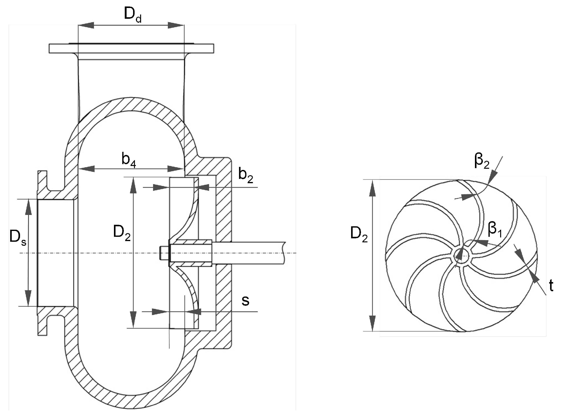
Figure 1.
Considered parameters of a vortex pump.
Figure 1.
Considered parameters of a vortex pump.
Figure 2.
(a) Vortex pump according to the covered design; and (b) schematic illustration of the covered design.
Figure 2.
(a) Vortex pump according to the covered design; and (b) schematic illustration of the covered design.
Figure 3.
Examples of pan impellers. (a) Rectangular shape; and (b) rounded shape.
Figure 3.
Examples of pan impellers. (a) Rectangular shape; and (b) rounded shape.
Figure 4.
(a) Vortex pump according to the open design; and (b) schematic illustration of the open design.
Figure 4.
(a) Vortex pump according to the open design; and (b) schematic illustration of the open design.
Figure 5.
Schematic view of impellers (a) with curved blades; and (b) with straight blades.
Figure 5.
Schematic view of impellers (a) with curved blades; and (b) with straight blades.
Figure 6.
Schematic view of impellers (a) with winglets; and (b) with front shroud.
Figure 6.
Schematic view of impellers (a) with winglets; and (b) with front shroud.
Figure 7.
(
a) Flow model for the covered design (adapted from [
31]); and (
b) flow model for the open design (adapted form [
34]).
Figure 7.
(
a) Flow model for the covered design (adapted from [
31]); and (
b) flow model for the open design (adapted form [
34]).
Figure 8.
Example for the presentation of the data.
Figure 8.
Example for the presentation of the data.
Figure 9.
(a) Head and pressure coefficient over impeller width; and (b) efficiency over impeller width.
Figure 9.
(a) Head and pressure coefficient over impeller width; and (b) efficiency over impeller width.
Figure 10.
(a) Head over impeller diameter; and (b) pressure coefficient over impeller diameter.
Figure 10.
(a) Head over impeller diameter; and (b) pressure coefficient over impeller diameter.
Figure 11.
Efficiency over impeller diameter.
Figure 11.
Efficiency over impeller diameter.
Figure 12.
(a) Pressure coefficient over number of blades; and (b) efficiency over number of blades.
Figure 12.
(a) Pressure coefficient over number of blades; and (b) efficiency over number of blades.
Figure 13.
(a) Head and pressure coefficient over blade outlet angle; and (b) efficiency over blade outlet angle.
Figure 13.
(a) Head and pressure coefficient over blade outlet angle; and (b) efficiency over blade outlet angle.
Figure 14.
(a) Head and efficiency over blade inlet angle; and (b) head and efficiency over blade thickness to impeller diameter.
Figure 14.
(a) Head and efficiency over blade inlet angle; and (b) head and efficiency over blade thickness to impeller diameter.
Figure 15.
(a) Head and efficiency over depth of winglet.; and (b) head and efficiency for impellers with and without a front shroud.
Figure 15.
(a) Head and efficiency over depth of winglet.; and (b) head and efficiency for impellers with and without a front shroud.
Figure 16.
(a) Head and pressure coefficient over volute width; and (b) efficiency over volute width.
Figure 16.
(a) Head and pressure coefficient over volute width; and (b) efficiency over volute width.
Figure 17.
(a) Head over covering; and (b) efficiency over covering.
Figure 17.
(a) Head over covering; and (b) efficiency over covering.
Figure 18.
(a) Head and pressure coefficient over suction pipe diameter; and (b) efficiency over suction pipe diameter.
Figure 18.
(a) Head and pressure coefficient over suction pipe diameter; and (b) efficiency over suction pipe diameter.
Figure 19.
(
a) Different inlet geometries of the suction pipes (based on [
1]; from left): a straight inlet, an inlet with a constriction and an inlet with a large radius of curvature; and (
b) influence of the suction pipe inlet geometry on the head and efficiency.
Figure 19.
(
a) Different inlet geometries of the suction pipes (based on [
1]; from left): a straight inlet, an inlet with a constriction and an inlet with a large radius of curvature; and (
b) influence of the suction pipe inlet geometry on the head and efficiency.
Figure 20.
(a) Head and efficiency over pressure pipe diameter; and (b) head and efficiency for different geometries of the casing.
Figure 20.
(a) Head and efficiency over pressure pipe diameter; and (b) head and efficiency for different geometries of the casing.
Figure 21.
(a) Head over rotation speed; and (b) efficiency over rotation speed.
Figure 21.
(a) Head over rotation speed; and (b) efficiency over rotation speed.
Table 1.
Assessed parameters in the articles.
Table 1.
Assessed parameters in the articles.
| Assessed Parameter | Prefix | Source(s) |
|---|
| Impeller | Impeller width | b2 | Rütschi [1], Guan et al. [2] ([3]), Wang [4]-a, Wang [4]-b, Zheng et al. [5], Sha et al. [6], Sha et al. [7], Sha et al. [8], Ohba et al. [9], Masanori [10] |
| Impeller diameter | D2 | Rütschi [1], Guan et al. [2] ([3]), Wang [4]-c, Wang [4]-d, Zheng et al. [5], Sha et al. [6], Sha et al. [7], Sha et al. [8], Ohba et al. [9]-a, Ohba et al. [9]-b, Lubieniecki [11]-a, Lubieniecki [11]-b, Lubieniecki [11]-c |
| Blade number | z | Rütschi [1], Guan et al. [2] ([3]), Masanori [10], |
| Blade outlet angle | β2 | Guan et al. [2] ([3]), Sha et al. [6], Sha et al. [8], Masanori [10] |
| Blade inlet angle | β1 | Guan et al. [2] ([3]) |
| Blade thickness | t | Guan et al. [2] ([3]) |
| Winglets and front shroud | - | Zheng et al. [5], Jiang et al. [12] ([13]), Gerlach et al. [14] |
| Casing | Volute width | b4 | Zheng et al. [5] ([15]), Sha et al. [6], Sha et al. [7], Sha et al. [8], Ohba et al. [9] |
| Covering | s | Rütschi [1]-a, Rütschi [1]-b, Sha and Hou [16] |
| Suction pipe diameter | Ds | Guan et al. [2] ([3]), Zheng et al. [5], Sha et al. [6], Ohba et al. [9] |
| Geometry of suction inlet pipe | - | Rütschi [1] |
| Pressure pipe diameter | Dd | Zheng et al. [5] |
| Geometry of casing | - | Zheng et al. [5] |
| Rotation speed | n | Li and Feng [17]-a, Li and Feng [17]-b, Sha and Bai [18] ([19]) |
Table 2.
Recommended ratios for geometric parameters in articles.
Table 2.
Recommended ratios for geometric parameters in articles.
| Source | Relationship | Targeted Improvement | Conclusion |
|---|
| Rütschi [1] | b2/Ds = (0.25–0.30) | Best efficiencies and head | Not confirmed |
| Ohba et al. [22] | b2/D2 = 0.25 | Best efficiencies | Not confirmed |
| Ohba et al. [22] | b4/D2 = 0.20 | Best efficiencies and head | Not confirmed |
| Zheng et al. [5] | b4/D2 = 0.255 | Best efficiencies and head | Not confirmed |
| Ohba et al. [22] | Ds/D2 = 0.45 | Best efficiencies and head | Not confirmed |
Table 3.
Geometric changes to the impeller and their effects on the pump-specific characteristics.
Table 3.
Geometric changes to the impeller and their effects on the pump-specific characteristics.
| Geometric Change by Increasing the Parameter | Effects on the Pump-Specific Characteristics |
|---|
| Parameter | Prefix | HBEP/ψBEP | ηBEP |
|---|
| Impeller width | b2 ↑ | ↑ | ↑ |
| Impeller diameter | D2 ↑ | ↑ | ↑ |
| Blade number | z ↑ | ↑ | ↑ |
| Blade outlet angle | β2↑ | ↑ | ↑ |
| Blade inlet angle | β1↑ | ↓ | ↓ |
| Blade thickness | t ↑ | ↓ | ↓ |
| Winglets | ↑ | ↑ | ↑ |
Table 4.
Geometric changes to the casing and changes to rotation speed and their effects on the pump-specific characteristics.
Table 4.
Geometric changes to the casing and changes to rotation speed and their effects on the pump-specific characteristics.
| Geometric Change by Increasing the Parameter | Effects on the Pump-Specific Characteristics |
|---|
| Parameter | Prefix | HBEP/ψBEP | ηBEP |
|---|
| Volute width | b4 ↑ | ↓ | ↓ |
| Covering | s ↑ | ↑ | ↑ |
| Suction pipe diameter | Ds ↑ | unambiguous | unambiguous |
| Pressure pipe diameter | Dd ↑ | ↓ | → |
| Geometry of suction pipe inlet | Straight | best | best |
| Geometry of casing | Ring | best | best |
| Rotation speed | n ↑ | ↑ | → |
Table 5.
Design recommendations for the impeller of a vortex pump.
Table 5.
Design recommendations for the impeller of a vortex pump.
| Parameter | Prefix | Recommendation |
|---|
| Impeller width | b2 | ↑ |
| Impeller diameter | D2 | ↑ |
| Blade number | z | ↑ |
| Blade outlet angle | β2 | ↑ |
| Blade inlet angle | β1 | ↓ |
| Blade thickness | t | ↓ |
| Winglets | - | ↑ |
Table 6.
Design recommendations for the casing and rotational speeds of a vortex pump.
Table 6.
Design recommendations for the casing and rotational speeds of a vortex pump.
| Parameter | Prefix | Recommendation |
|---|
| Volute width | b4 | ↓ |
| Covering | s | ↑ |
| Pressure pipe diameter | Dd | ↓ |
| Geometry of suction pipe inlet | - | Straight |
| Geometry of casing | - | Ring |
| Rotation speed | n | ↑ |
© 2017 by the authors; licensee MDPI, Basel, Switzerland. This article is an open access article distributed under the terms and conditions of the Creative Commons Attribution (CC-BY) license (http://creativecommons.org/licenses/by/4.0/).


